EP0130501A2 - Système de freinage hydraulique et/ou pneumatique pour véhicules automobiles - Google Patents
Système de freinage hydraulique et/ou pneumatique pour véhicules automobiles Download PDFInfo
- Publication number
- EP0130501A2 EP0130501A2 EP84107172A EP84107172A EP0130501A2 EP 0130501 A2 EP0130501 A2 EP 0130501A2 EP 84107172 A EP84107172 A EP 84107172A EP 84107172 A EP84107172 A EP 84107172A EP 0130501 A2 EP0130501 A2 EP 0130501A2
- Authority
- EP
- European Patent Office
- Prior art keywords
- brake
- pressure
- locking
- circuit
- control
- Prior art date
- Legal status (The legal status is an assumption and is not a legal conclusion. Google has not performed a legal analysis and makes no representation as to the accuracy of the status listed.)
- Granted
Links
- 238000011156 evaluation Methods 0.000 claims abstract description 33
- 230000001105 regulatory effect Effects 0.000 claims abstract description 13
- 238000011144 upstream manufacturing Methods 0.000 claims description 6
- 239000003638 chemical reducing agent Substances 0.000 claims description 5
- 230000008030 elimination Effects 0.000 claims description 3
- 238000003379 elimination reaction Methods 0.000 claims description 3
- 230000000903 blocking effect Effects 0.000 description 17
- 238000010586 diagram Methods 0.000 description 11
- 230000009467 reduction Effects 0.000 description 7
- 238000013461 design Methods 0.000 description 3
- 238000000034 method Methods 0.000 description 3
- 230000008569 process Effects 0.000 description 3
- 230000009471 action Effects 0.000 description 2
- 230000033228 biological regulation Effects 0.000 description 2
- 230000000694 effects Effects 0.000 description 2
- 210000002023 somite Anatomy 0.000 description 2
- 241000269627 Amphiuma means Species 0.000 description 1
- 230000004913 activation Effects 0.000 description 1
- 230000008901 benefit Effects 0.000 description 1
- 238000010276 construction Methods 0.000 description 1
- 230000007547 defect Effects 0.000 description 1
- 230000001419 dependent effect Effects 0.000 description 1
- 238000011161 development Methods 0.000 description 1
- 230000018109 developmental process Effects 0.000 description 1
- 238000005516 engineering process Methods 0.000 description 1
- 239000012530 fluid Substances 0.000 description 1
- 238000012423 maintenance Methods 0.000 description 1
- 239000012528 membrane Substances 0.000 description 1
Images



Classifications
-
- B—PERFORMING OPERATIONS; TRANSPORTING
- B60—VEHICLES IN GENERAL
- B60T—VEHICLE BRAKE CONTROL SYSTEMS OR PARTS THEREOF; BRAKE CONTROL SYSTEMS OR PARTS THEREOF, IN GENERAL; ARRANGEMENT OF BRAKING ELEMENTS ON VEHICLES IN GENERAL; PORTABLE DEVICES FOR PREVENTING UNWANTED MOVEMENT OF VEHICLES; VEHICLE MODIFICATIONS TO FACILITATE COOLING OF BRAKES
- B60T8/00—Arrangements for adjusting wheel-braking force to meet varying vehicular or ground-surface conditions, e.g. limiting or varying distribution of braking force
- B60T8/32—Arrangements for adjusting wheel-braking force to meet varying vehicular or ground-surface conditions, e.g. limiting or varying distribution of braking force responsive to a speed condition, e.g. acceleration or deceleration
- B60T8/34—Arrangements for adjusting wheel-braking force to meet varying vehicular or ground-surface conditions, e.g. limiting or varying distribution of braking force responsive to a speed condition, e.g. acceleration or deceleration having a fluid pressure regulator responsive to a speed condition
- B60T8/38—Arrangements for adjusting wheel-braking force to meet varying vehicular or ground-surface conditions, e.g. limiting or varying distribution of braking force responsive to a speed condition, e.g. acceleration or deceleration having a fluid pressure regulator responsive to a speed condition including valve means of the relay or driver controlled type
-
- B—PERFORMING OPERATIONS; TRANSPORTING
- B60—VEHICLES IN GENERAL
- B60T—VEHICLE BRAKE CONTROL SYSTEMS OR PARTS THEREOF; BRAKE CONTROL SYSTEMS OR PARTS THEREOF, IN GENERAL; ARRANGEMENT OF BRAKING ELEMENTS ON VEHICLES IN GENERAL; PORTABLE DEVICES FOR PREVENTING UNWANTED MOVEMENT OF VEHICLES; VEHICLE MODIFICATIONS TO FACILITATE COOLING OF BRAKES
- B60T8/00—Arrangements for adjusting wheel-braking force to meet varying vehicular or ground-surface conditions, e.g. limiting or varying distribution of braking force
- B60T8/17—Using electrical or electronic regulation means to control braking
- B60T8/176—Brake regulation specially adapted to prevent excessive wheel slip during vehicle deceleration, e.g. ABS
- B60T8/1766—Proportioning of brake forces according to vehicle axle loads, e.g. front to rear of vehicle
-
- B—PERFORMING OPERATIONS; TRANSPORTING
- B60—VEHICLES IN GENERAL
- B60T—VEHICLE BRAKE CONTROL SYSTEMS OR PARTS THEREOF; BRAKE CONTROL SYSTEMS OR PARTS THEREOF, IN GENERAL; ARRANGEMENT OF BRAKING ELEMENTS ON VEHICLES IN GENERAL; PORTABLE DEVICES FOR PREVENTING UNWANTED MOVEMENT OF VEHICLES; VEHICLE MODIFICATIONS TO FACILITATE COOLING OF BRAKES
- B60T8/00—Arrangements for adjusting wheel-braking force to meet varying vehicular or ground-surface conditions, e.g. limiting or varying distribution of braking force
- B60T8/32—Arrangements for adjusting wheel-braking force to meet varying vehicular or ground-surface conditions, e.g. limiting or varying distribution of braking force responsive to a speed condition, e.g. acceleration or deceleration
- B60T8/34—Arrangements for adjusting wheel-braking force to meet varying vehicular or ground-surface conditions, e.g. limiting or varying distribution of braking force responsive to a speed condition, e.g. acceleration or deceleration having a fluid pressure regulator responsive to a speed condition
- B60T8/44—Arrangements for adjusting wheel-braking force to meet varying vehicular or ground-surface conditions, e.g. limiting or varying distribution of braking force responsive to a speed condition, e.g. acceleration or deceleration having a fluid pressure regulator responsive to a speed condition co-operating with a power-assist booster means associated with a master cylinder for controlling the release and reapplication of brake pressure through an interaction with the power assist device, i.e. open systems
- B60T8/447—Reducing the boost of the power-assist booster means to reduce brake pressure
- B60T8/448—Reducing the boost of the power-assist booster means to reduce brake pressure the power-assist booster means being a vacuum or compressed air booster
Definitions
- the invention relates to a hydraulic and / or pneumatic brake system for motor vehicles of the type mentioned in the preamble of claim 1.
- a hydraulic and / or pneumatic brake system for motor vehicles of the type mentioned in the preamble of claim 1.
- Such an anti-lock brake system for motor vehicles is known, for example, from US Pat. No. 4,022,514.
- the common pressure modulator and the valve devices located in the two independent brake circuits are arranged and linked to one another in such a way that when the valve device is switched on - by the electronic evaluation and control circuit - the hydraulic connection from the associated rear wheel brake to the master brake cylinder of the brake system is interrupted and and instead whose a pressure connection to the pressure modulator is established so that the brake pressure of this rear wheel brake by the pressure modulator - controlled by the electronic evaluation and control circuit - the Control requirements are lowered accordingly until the risk of blocking is eliminated and then raised again, if necessary this cycle can also be repeated several times in succession. If a risk of locking is signaled for both monitored wheels, activation of both valve devices disconnects both rear wheel brakes from the master brake cylinder and connects them to the pressure modulator. Depending on the requirement, one or the other or both rear brakes are therefore connected to the pressure modulator in terms of pressure.
- the pressure modulator itself contains a pressure chamber, the chamber volume of which can be controlled, enlarged and reduced by moving a piston, so that - if this pressure chamber is connected in terms of pressure via the valve devices to one or the other or both brake pressure lines of the rear wheel brakes - the brake pressure there after enlarging or reducing the chamber volume is lowered or raised again.
- the direct inclusion of the pressure chamber of the pressure modulator in the hydraulic system of the brake system naturally means that a correspondingly larger amount of hydraulic fluid is required for the hydraulic brake system.
- the piston is displaced with the aid of two auxiliary chambers separated by a membrane or the like, which - controlled by the electronic evaluation and control circuit - are acted upon either by a vacuum or a pressure source.
- sensors are only assigned to the rear wheels and the pressure modulator only acts on the brake pressure lines of the rear wheel brakes.
- the front wheels are not monitored and not regulated.
- the invention has for its object to further improve a hydraulic and / or pneumatic brake system for motor vehicles of the type mentioned in the preamble of claim 1 and to simplify its effort.
- the brake booster itself which is present anyway, is used in particular as a pressure modulator, for which purpose it is modified in such a way that it depends on the control requirement can be switched by the electronic evaluation and control circuit either in a first state supporting the brake pedal force or in a second state counteracting the brake pedal force, so that the downstream master cylinder acted upon by it accordingly brings about an increase or decrease in brake pressure.
- an anti-lock braking system for motor vehicles is already known (DE-OS 15 55 579) in which the brake booster acts as a pressure modulator and, if a danger of locking is signaled on one of the wheels, from its first state, which supports the brake pedal force, to a second state which counteracts the brake pedal force State is switchable.
- This known anti-lock braking system however, has the essential defect that only the brake pressure of the entire brake system, i. H.
- the brake pressure either only for the brake of one of the vehicle wheels, depending on the design of the system , for the brakes of the wheels only one, e.g. B. regulated diagonal brake circuit or for the brakes of all vehicle wheels, d. H. can be lowered, held and raised again.
- FIG. 1 shows the hydraulic brake system of a motor vehicle with two independent, diagonally divided brake circuits I and II.
- the front wheel 1.1 and the rear wheel 1.2 are supplied by the brake circuit I, while the front wheel 2.1 and the rear wheel 2.2 belong to the second brake circuit II.
- the front brakes are numbered 11 and the rear brakes 12.
- the brake pressure for the front and rear wheel brakes is generated in a conventional manner in a master brake cylinder 4, which is actuated by the brake pedal 9 with the interposition of a brake booster 6.
- Brake force distributors in particular brake pressure reducers, can be arranged in the brake pressure lines leading to the rear wheel brakes 12, which are shown in dashed lines and numbered 13.
- the brake system shown does not differ from conventional brake systems; In this scope, it is particularly designed so that it meets the legal requirements, z. B. the regulation EG 71/320 or US standard 105, which u. a. means that even if the brake booster or one of the two brake circuits fails, it still causes sufficient vehicle deceleration.
- Sensors 3 are arranged on the vehicle wheels 1.1 to 2.2, which detect the rotational speed and / or deceleration of the vehicle wheels and feed corresponding signals nl. L to n2.2 to an electronic evaluation and control circuit 8, which determines from them in a known manner whether and which of the monitored vehicle wheels tend to lock or begin to block or which previously blocked or lock-prone wheel starts to run freely again.
- control signals S1 to S4 are emitted by means of a logic circuit contained in the evaluation and control circuit, by means of which various valve devices etc. are switched on or off in order to eliminate the risk of blocking occurring in the desired manner.
- a valve device 5.1 or 5.2 which acts as a pure shut-off valve and is switched on and off, is arranged in such a way that it belongs between the master brake cylinder 4 and both the associated brake circuit There are wheel brakes.
- These check valves can be switched by the electronic evaluation and control circuit 8 from their open state to a locked or closed state, so that the part of the brake circuit located behind the blocked valve device is connected to the master brake cylinder 4 from the valve valve located in front of this valve device standing part of this brake circuit is completely separate.
- the pressure in the part of the brake circuit located behind the blocked valve device thus remains constant irrespective of whether there is a pressure decrease or a pressure increase in the part of the brake circuit located in front of the valve device.
- valve devices 7a and 7b which can be switched on and off by the evaluation and control circuit 8 are provided, with the aid of which the direction of action of the brake booster 6 used in the exemplary embodiment can be switched over as required, namely into a first one which supports the brake pedal force State or in a second state counteracting the brake pedal force.
- the brake booster 6, which can be switched in its direction of action via the valve devices 7a and 7b, is now used not only as a conventional brake booster, with the aid of which the forces to be exerted on the brake pedal 9 by the vehicle driver during normal braking operation (no tendency of the vehicle wheels to lock) are also reduced as a pressure modulator, with the aid of which the brake pressure is regulated if there is a risk of the vehicle wheels becoming blocked, depending on the requirements, the brake pressure is regulated either in only one or in several brake circuits by reducing the pressure, maintaining pressure and increasing the pressure in accordance with the control signals emitted by the evaluation and control circuit 8.
- the electronic evaluation and control circuit 8 can react very flexibly when the risk of blocking is signaled by the sensors 3, in order to avoid the risk of blocking by appropriate regulation of the brake pressure to eliminate.
- the brake booster 6 working as a pressure modulator, in accordance with the control signals emitted by the control circuit 8, causes pressure drops or pressure increases in both brake circuits I and II or only in one of the two brake circuits effective, while the pressure in the brake circuit behind a shut-off valve switched to its locked state is kept constant at the value prevailing there (pressure maintenance).
- shut-off valves 5.1 and 5.2 While two shut-off valves 5.1 and 5.2 are provided in the exemplary embodiment according to FIG. 1, the actuation of which affects a complete brake circuit I or II, a total of four shut-off valves 5.1, 5.1 'or 5.2 and 5.2' are provided in the exemplary embodiment according to FIG that the brake pressure for each of the vehicle wheels can be shut off independently of the others, which of course enables finer control of the individual wheel brake pressures. While in the exemplary embodiment according to FIG. 1, together with the brake pressure of the front wheel, which is at risk of locking, the brake pressure of the brake circuit located in the same brake circuit is also inevitable. U. blockage-prone rear wheel is lowered - whereby usable braking force is lost - in the exemplary embodiment according to FIG.
- this rear wheel can advantageously be decoupled, at least in terms of pressure, from the front wheel lying in the same brake circuit by blocking the additional blocking valve 5.1 'or 5.2' during the phases in which the brake pressure of this wheel is reduced by the pressure modulator. Since the brake pressure in the rear wheel partial brake circuit thus separated is kept constant at the value that was present at the time the lock valve was actuated, a higher braking force is thus applied via this rear wheel than without actuating the additional lock valve.
- control measures can be carried out for all braking situations that occur, which ensure proper driving and braking behavior of the vehicle.
- the brake pressure control for the two brake circuits I and II with the aid of the brake booster 6, which can be used as a single pressure modulator for both circuits, and the check valves 5.1 etc. is not carried out according to a rigid scheme, but alternately as required and if necessary.
- the rule requirements can be very different. When driving straight ahead and on a smooth road, it is of primary importance to achieve the greatest possible deceleration of the vehicle. Therefore, it is advantageous to design the electronic evaluation and control circuit 8 so that it gives priority to the brake circuit in the pressure control by means of the pressure modulator, in which a pressure increase is necessary or expedient due to the evaluated sensor signals and the brake circuit in which the at the same time due to the evaluated sensor signals a pressure drop would be expedient, initially ignored. If this causes the wheel of this second brake circuit, which is signaled by the sensors to be jammed, to slip and ultimately even lock, this is almost irrelevant, since the brake pressure for the wheels of the first brake circuit is optimally regulated.
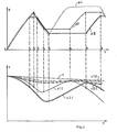
- FIG. 4 shows a control cycle corresponding to the situation described under point 6, the different pressures in the braking system being shown in the upper part of the diagram and the different speeds each being shown as a function of time in the lower part of the diagram, the pressure modulator and the Brake power booster delivered pressure p4 punctured, the brake pressure pI in the brake circuit I are shown as a full line and the brake pressure pII in the brake circuit II as a double full line.
- t o denotes the start of braking.
- the pressure in the brake system therefore increases, initially in both brake circuits I and II in the same way.
- the brake system is dimensioned in such a way that the coefficient of friction of the front wheels is greater than that of the rear wheels.
- the danger of locking is signaled for the right front wheel.
- the check valve 5.2 of the associated brake circuit II switched to the locked state so that the brake pressure for the right front wheel, which is prone to locking, is kept constant.
- the shut-off valves 5.1 and 5.2 each have a differential pressure switch 10 connected in parallel, which generates a signal that can be supplied to the electronic evaluation and control circuit when the pressure before the The check valve is higher than behind the check valve and a switchover of the check valve from the locked to the open state is only permitted when the pressure upstream of the check valve is at least approximately as high as behind the check valve.
- control circuit 8 is signaled that the left front wheel 1.1 is accelerated again (the control deviation, ie slip, but still exists).
- the control circuit 8 is signaled that the right front wheel 2.1 is now also being accelerated again (the control deviation still exists), whereupon on the one hand the check valve 5.2 arranged in the brake circuit of this front wheel 2.1, the brake circuit II, is switched on and also by the pressure modulator 4 / 6 separated, and on the other hand the brake booster 6 of the pressure modulator is switched back to its first state (pressure build-up) which supports the brake pedal force, so that the pressure p4 emitted by the pressure modulator increases. Since the two shut-off valves 5.1 and 5.2 remain switched on due to the control deviations that are still signaled, the increasing pressure p4 initially has no effect in the two brake circuits I and II.
- the electronic control and evaluation circuit 8 in this constellation gives priority to the "pressure build-up” control requirement over the “pressure reduction” control requirement and consequently the shut-off valve 5.1 of the brake circuit I is switched on again, with the result that the pressure pI of this circuit is kept constant, while the pressure plI of the other circuit can increase.
- FIG. 5 describes a control cycle of how it can occur when cornering or on an asymmetrical road and how it is described under point 5.
- the designation corresponds to the designation chosen in Figure 4.
- t'p denotes the start of a braking process.
- the pressure p4 of the brake system which is released by the master brake cylinder 4 initially rises in the usual way, in both brake circuits I and II.
- the lower part of the diagram shows that the rotational speed v2.1 and vl.2 of the right front wheel 2.1 and the right rear wheel 1.2 drops sharply because these wheels z. B. run on the street side with a particularly low coefficient of friction or when driving through a curve on the inside of the curve.
- the right rear wheel 1.2 also begins to slip.
- the electronic control and evaluation circuit 8 signals a risk of locking for this wheel, according to point 4 of the list above, this does not trigger a control intervention in order to counteract this, that is to say the pressure pI is permitted in the rear wheel assigned brake circuit I continues to increase.
- both check valves would have to be switched off, ie in their open state.
- the shut-off valve 5.1 is open, but the shut-off valve 5.2 is switched on at the time t ', that is to say put in the locked state.
- the check valve 5.2 previously blocked would be switched over to its open state at time t 3 .
- FIG. 5 shows that the check valves 5.1 and 5.2 - as shown in the exemplary embodiment according to FIG.
- the electronic control and evaluation circuit is designed so that the check valve is switched from the locked to the open state only when this signal from the differential pressure switch is received, ie only when the pressure upstream of the check valve is at least approximately is as high as behind the check valve.
- the control circuit 8 is signaled that the left front wheel 1.1. is accelerated again (a control deviation as such still exists), so that a further pressure reduction for this wheel is no longer necessary. Consequently, the control circuit 8 turns on the shutoff valve 5.1, so that the pressure pI of the brake circuit I is kept constant despite the pressure p4 of the pressure modulator which continues to decrease.
- the pressure p4 of the pressure modulator has dropped so far that the inlet pressure of the presupposed differential pressure switch 10 is at least approximately as high as its outlet pressure, which is signaled to the control circuit 8 by a corresponding signal pl.
- the previously blocked shut-off valve 5.2 is opened, so that the pressure pII of the brake circuit II drops in accordance with the pressure p4.
- the control circuit 8 is signaled that the risk of locking for the left front wheel 1.1 has been eliminated because the rotational speed has probably reached a correspondingly high value.
- this front wheel 1.1. there is therefore the rule requirement "pressure build-up" at time t ' 6 .
- the right front wheel 2.1 there is still the opposite requirement of "pressure reduction”.
- priority must be given to the control requirement of the front wheel, which is in the same braking circuit as the blocked rear wheel, that is to say the control requirement of the left front wheel 1.1.
- shut-off valve 5.2 is switched on in order to keep the pressure pII of the other front wheel, namely the right front wheel 2.2 constant, and on the other hand the brake booster 6 of the pressure modulator is switched back to its first state supporting the brake pedal, so that the pressure p4 begins to rise again.
- the shut-off valve 5.1 which has been switched on since the time t ' 4 and which would be switched off, ie opened in the case of arrangements according to FIGS in the case in which differential pressure switches 10 connected in parallel according to FIG. 3 are required, continue to be switched on because the inlet pressure and outlet pressure at the differential pressure switch assigned to the blocked shut-off valve 5.1 are of different sizes. The pressure pI therefore initially retains its value.
- the pressure p4 of the pressure modulator has risen so far that the inlet and outlet pressure of the aforementioned differential pressure switch match at least approximately, so that the shut-off valve 5.1 is switched off and the pressure pI rises accordingly.
- the other processes are similar to the processes described above.
Landscapes
- Engineering & Computer Science (AREA)
- Transportation (AREA)
- Mechanical Engineering (AREA)
- Physics & Mathematics (AREA)
- Fluid Mechanics (AREA)
- Regulating Braking Force (AREA)
Applications Claiming Priority (2)
| Application Number | Priority Date | Filing Date | Title |
|---|---|---|---|
| DE19833322786 DE3322786A1 (de) | 1983-06-24 | 1983-06-24 | Hydraulisches und/oder pneumatisches bremssystem fuer kraftfahrzeuge |
| DE3322786 | 1983-06-24 |
Publications (3)
| Publication Number | Publication Date |
|---|---|
| EP0130501A2 true EP0130501A2 (fr) | 1985-01-09 |
| EP0130501A3 EP0130501A3 (en) | 1987-11-25 |
| EP0130501B1 EP0130501B1 (fr) | 1990-05-02 |
Family
ID=6202301
Family Applications (1)
| Application Number | Title | Priority Date | Filing Date |
|---|---|---|---|
| EP84107172A Expired - Lifetime EP0130501B1 (fr) | 1983-06-24 | 1984-06-22 | Système de freinage hydraulique et/ou pneumatique pour véhicules automobiles |
Country Status (2)
| Country | Link |
|---|---|
| EP (1) | EP0130501B1 (fr) |
| DE (2) | DE3322786A1 (fr) |
Cited By (6)
| Publication number | Priority date | Publication date | Assignee | Title |
|---|---|---|---|---|
| GB2201743A (en) * | 1987-03-06 | 1988-09-07 | Teves Gmbh Alfred | Brake system with anti-skid control and/or traction slip control |
| EP0360013A1 (fr) * | 1988-09-17 | 1990-03-28 | ALFRED TEVES GmbH | Installation de freinage à anti-blocage pour véhicules automobiles |
| WO1990005081A3 (fr) * | 1988-11-03 | 1990-06-28 | Teves Gmbh Alfred | Systeme de freinage hydraulique a glissement controle |
| WO1990014257A1 (fr) * | 1989-05-26 | 1990-11-29 | Alfred Teves Gmbh | Unite d'actionnement pour systeme de freinage a anti-derapeur automatique de vehicules a moteur |
| DE19611550A1 (de) * | 1996-03-23 | 1997-09-25 | Teves Gmbh Alfred | Pumpenloses Bremsdruckregelsystem für Kraftfahrzeuge |
| CN107202685A (zh) * | 2017-06-15 | 2017-09-26 | 吉林大学 | 一种电子机械制动助力器硬件在环仿真试验台及试验方法 |
Families Citing this family (3)
| Publication number | Priority date | Publication date | Assignee | Title |
|---|---|---|---|---|
| DE3660890D1 (en) | 1985-04-25 | 1988-11-17 | Volkswagen Ag | Braking power booster for a hydraulic braking system of a motor vehicle |
| DE3619793A1 (de) * | 1985-07-17 | 1987-01-22 | Volkswagen Ag | Druckmittelbetaetigte bremsanlage fuer kraftfahrzeuge |
| AT391111B (de) * | 1986-07-01 | 1990-08-27 | Steyr Daimler Puch Ag | Bremseinrichtung fuer kraftfahrzeuge |
Family Cites Families (10)
| Publication number | Priority date | Publication date | Assignee | Title |
|---|---|---|---|---|
| DE1655383C3 (de) * | 1967-04-08 | 1974-02-28 | Teldix Gmbh, 6900 Heidelberg | Antiblockierregelsystem für eine kolbengesteuerte hydraulische Bremsanlage |
| FR2052236A5 (fr) * | 1969-07-31 | 1971-04-09 | Dba | |
| DE1941098C3 (de) * | 1969-08-13 | 1982-02-04 | Teldix Gmbh, 6900 Heidelberg | Blockiergeschützte Fahrzeugbremsanlage |
| US3829170A (en) * | 1970-10-26 | 1974-08-13 | E Rockwell | Anti-skid brake system |
| DE2215608A1 (de) * | 1972-03-30 | 1973-10-11 | Teldix Gmbh | Antiblockierregelsystem |
| DE2751143A1 (de) * | 1977-06-14 | 1979-05-17 | Bosch Gmbh Robert | Pneumatisch-hydraulische bremsvorrichtung fuer fahrzeuge |
| DE2825087A1 (de) * | 1978-06-08 | 1979-12-13 | Bosch Gmbh Robert | Blockierschutzeinrichtung fuer eine hydraulische bremsanlage |
| DE2830580A1 (de) * | 1978-07-12 | 1980-02-28 | Wabco Fahrzeugbremsen Gmbh | Verfahren und einrichtung zur regelung des bremsdruckes in blockiergeschuetzten fahrzeugbremsanlagen |
| DE2911966A1 (de) * | 1979-03-27 | 1980-10-16 | Bosch Gmbh Robert | Blockierschutz-einrichtung |
| DE3109372A1 (de) * | 1981-03-12 | 1982-09-30 | Volkswagenwerk Ag, 3180 Wolfsburg | "pumpenloses hydraulisches bremssystem fuer kraftfahrzeuge" |
-
1983
- 1983-06-24 DE DE19833322786 patent/DE3322786A1/de not_active Withdrawn
-
1984
- 1984-06-22 EP EP84107172A patent/EP0130501B1/fr not_active Expired - Lifetime
- 1984-06-22 DE DE8484107172T patent/DE3482102D1/de not_active Expired - Lifetime
Cited By (8)
| Publication number | Priority date | Publication date | Assignee | Title |
|---|---|---|---|---|
| GB2201743A (en) * | 1987-03-06 | 1988-09-07 | Teves Gmbh Alfred | Brake system with anti-skid control and/or traction slip control |
| US4828332A (en) * | 1987-03-06 | 1989-05-09 | Alfred Teves Gmbh | Brake system with anti skid control and/or traction slip control |
| GB2201743B (en) * | 1987-03-06 | 1991-05-01 | Teves Gmbh Alfred | Brake system with anti-skid control and/or traction slip control |
| EP0360013A1 (fr) * | 1988-09-17 | 1990-03-28 | ALFRED TEVES GmbH | Installation de freinage à anti-blocage pour véhicules automobiles |
| WO1990005081A3 (fr) * | 1988-11-03 | 1990-06-28 | Teves Gmbh Alfred | Systeme de freinage hydraulique a glissement controle |
| WO1990014257A1 (fr) * | 1989-05-26 | 1990-11-29 | Alfred Teves Gmbh | Unite d'actionnement pour systeme de freinage a anti-derapeur automatique de vehicules a moteur |
| DE19611550A1 (de) * | 1996-03-23 | 1997-09-25 | Teves Gmbh Alfred | Pumpenloses Bremsdruckregelsystem für Kraftfahrzeuge |
| CN107202685A (zh) * | 2017-06-15 | 2017-09-26 | 吉林大学 | 一种电子机械制动助力器硬件在环仿真试验台及试验方法 |
Also Published As
| Publication number | Publication date |
|---|---|
| DE3322786A1 (de) | 1985-01-10 |
| EP0130501A3 (en) | 1987-11-25 |
| EP0130501B1 (fr) | 1990-05-02 |
| DE3482102D1 (de) | 1990-06-07 |
Similar Documents
| Publication | Publication Date | Title |
|---|---|---|
| DE3327401C2 (de) | Hydraulische Bremsanlage mit Antriebs- und Bremsschlupfregelung | |
| DE3418520C2 (fr) | ||
| EP0726856B1 (fr) | Systeme de freinage a regulation antiblocage electronique | |
| DE3706663C2 (fr) | ||
| DE3302642A1 (de) | Antiblockiersystem fuer ein zweirad-strassenfahrzeug mit hydraulischer zweikreis-bremsanlage | |
| DE3542419A1 (de) | Hydraulische kraftfahrzeugbremsanlage mit blockierschutz | |
| DE3425672C2 (de) | Bremsanlage für Kraftfahrzeuge | |
| DE3338826C2 (fr) | ||
| DE3624722A1 (de) | Ventilanordnung fuer fahrzeug-bremsanlagen mit elektronischer blockier- und antriebsschlupfregelung | |
| DE2102131A1 (de) | Antiblockierregelsystem | |
| EP0281769A2 (fr) | Installation de freinage hydraulique pour un véhicule avec un dispositif d'antiblocage | |
| EP0547407A1 (fr) | Système de freinage à air comprimé, en particulier pour véhicules commerciales | |
| DE3314802A1 (de) | Bremsschlupfgeregelte bremsanlage | |
| DE3705311C2 (de) | Mehrkreisige hydraulische Bremsanlage für Kraftfahrzeuge | |
| DE4004270A1 (de) | Bremsanlage | |
| DE2638190C2 (de) | Drucksteuereinheit für hydraulische Fahrzeugbremsanlagen | |
| EP0130501B1 (fr) | Système de freinage hydraulique et/ou pneumatique pour véhicules automobiles | |
| EP0898532B1 (fr) | Dispositif maitre-cylindre pour un systeme de freinage hydraulique de vehicule | |
| DE1505734A1 (de) | Bremssystem mit Verhindern des Schleuderns bzw. Gleitens fuer Fahrzeuge | |
| EP0837803B1 (fr) | Systeme de freinage hydraulique pour vehicule | |
| DE2737937C2 (de) | Hydraulische Bremsanlage für ein Fahrzeug mit einer Blockierschutzeinrichtung | |
| DE3136617C2 (fr) | ||
| DE3706661A1 (de) | Antiblockier-system | |
| DE3640453A1 (de) | Bremsschlupfgeregelte zweikreis-fahrzeugbremsanlage | |
| DE20103129U1 (de) | Vorrichtung zur Veränderung der Drehzahl der angetriebenen Räder eines Kraftfahrzeuges |
Legal Events
| Date | Code | Title | Description |
|---|---|---|---|
| PUAI | Public reference made under article 153(3) epc to a published international application that has entered the european phase |
Free format text: ORIGINAL CODE: 0009012 |
|
| AK | Designated contracting states |
Designated state(s): DE FR GB IT |
|
| RAP1 | Party data changed (applicant data changed or rights of an application transferred) |
Owner name: VOLKSWAGEN AKTIENGESELLSCHAFT |
|
| PUAL | Search report despatched |
Free format text: ORIGINAL CODE: 0009013 |
|
| AK | Designated contracting states |
Kind code of ref document: A3 Designated state(s): DE FR GB IT |
|
| 17P | Request for examination filed |
Effective date: 19880326 |
|
| 17Q | First examination report despatched |
Effective date: 19880914 |
|
| GRAA | (expected) grant |
Free format text: ORIGINAL CODE: 0009210 |
|
| AK | Designated contracting states |
Kind code of ref document: B1 Designated state(s): DE FR GB IT |
|
| REF | Corresponds to: |
Ref document number: 3482102 Country of ref document: DE Date of ref document: 19900607 |
|
| ET | Fr: translation filed | ||
| ITTA | It: last paid annual fee | ||
| ITF | It: translation for a ep patent filed | ||
| GBT | Gb: translation of ep patent filed (gb section 77(6)(a)/1977) | ||
| PLBE | No opposition filed within time limit |
Free format text: ORIGINAL CODE: 0009261 |
|
| STAA | Information on the status of an ep patent application or granted ep patent |
Free format text: STATUS: NO OPPOSITION FILED WITHIN TIME LIMIT |
|
| 26N | No opposition filed | ||
| ITPR | It: changes in ownership of a european patent |
Owner name: OFFERTA DI LICENZA AL PUBBLICO |
|
| PGFP | Annual fee paid to national office [announced via postgrant information from national office to epo] |
Ref country code: FR Payment date: 19920616 Year of fee payment: 9 |
|
| PGFP | Annual fee paid to national office [announced via postgrant information from national office to epo] |
Ref country code: DE Payment date: 19930518 Year of fee payment: 10 |
|
| PGFP | Annual fee paid to national office [announced via postgrant information from national office to epo] |
Ref country code: GB Payment date: 19930615 Year of fee payment: 10 |
|
| PG25 | Lapsed in a contracting state [announced via postgrant information from national office to epo] |
Ref country code: FR Effective date: 19940228 |
|
| REG | Reference to a national code |
Ref country code: FR Ref legal event code: ST |
|
| PG25 | Lapsed in a contracting state [announced via postgrant information from national office to epo] |
Ref country code: GB Effective date: 19940622 |
|
| GBPC | Gb: european patent ceased through non-payment of renewal fee |
Effective date: 19940622 |
|
| PG25 | Lapsed in a contracting state [announced via postgrant information from national office to epo] |
Ref country code: DE Effective date: 19950301 |