EP0130511A2 - Relais électromagnétique avec un ressort de contact inverseur - Google Patents
Relais électromagnétique avec un ressort de contact inverseur Download PDFInfo
- Publication number
- EP0130511A2 EP0130511A2 EP84107230A EP84107230A EP0130511A2 EP 0130511 A2 EP0130511 A2 EP 0130511A2 EP 84107230 A EP84107230 A EP 84107230A EP 84107230 A EP84107230 A EP 84107230A EP 0130511 A2 EP0130511 A2 EP 0130511A2
- Authority
- EP
- European Patent Office
- Prior art keywords
- rocker
- armature
- foot piece
- opening
- spring
- Prior art date
- Legal status (The legal status is an assumption and is not a legal conclusion. Google has not performed a legal analysis and makes no representation as to the accuracy of the status listed.)
- Granted
Links
Images

Classifications
-
- H—ELECTRICITY
- H01—ELECTRIC ELEMENTS
- H01H—ELECTRIC SWITCHES; RELAYS; SELECTORS; EMERGENCY PROTECTIVE DEVICES
- H01H50/00—Details of electromagnetic relays
- H01H50/54—Contact arrangements
- H01H50/60—Contact arrangements moving contact being rigidly combined with movable part of magnetic circuit
-
- H—ELECTRICITY
- H01—ELECTRIC ELEMENTS
- H01H—ELECTRIC SWITCHES; RELAYS; SELECTORS; EMERGENCY PROTECTIVE DEVICES
- H01H1/00—Contacts
- H01H1/12—Contacts characterised by the manner in which co-operating contacts engage
- H01H1/14—Contacts characterised by the manner in which co-operating contacts engage by abutting
- H01H1/20—Bridging contacts
- H01H1/2075—T-shaped bridge; bridging contact has lateral arm for mounting resiliently or on a pivot
-
- H—ELECTRICITY
- H01—ELECTRIC ELEMENTS
- H01H—ELECTRIC SWITCHES; RELAYS; SELECTORS; EMERGENCY PROTECTIVE DEVICES
- H01H50/00—Details of electromagnetic relays
- H01H50/16—Magnetic circuit arrangements
- H01H50/18—Movable parts of magnetic circuits, e.g. armature
- H01H50/32—Latching movable parts mechanically
- H01H50/326—Latching movable parts mechanically with manual intervention, e.g. for testing, resetting or mode selection
-
- H—ELECTRICITY
- H01—ELECTRIC ELEMENTS
- H01H—ELECTRIC SWITCHES; RELAYS; SELECTORS; EMERGENCY PROTECTIVE DEVICES
- H01H51/00—Electromagnetic relays
- H01H51/22—Polarised relays
- H01H51/2227—Polarised relays in which the movable part comprises at least one permanent magnet, sandwiched between pole-plates, each forming an active air-gap with parts of the stationary magnetic circuit
Definitions
- the invention relates to an electromagnetic relay, consisting of a drive system with excitation coil and yoke plates, which form a closed magnetic circuit with a pivotable armature, the armature being connected to a changeover spring, the contacts of which cooperate with fixed contacts on the spring bracket.
- a relay mentioned at the outset has become known, for example, from DE-OS 30 21 184, which goes back to the same applicant.
- This known relay is bistable and the armature is designed as a movable rocker.
- the changeover spring arranged on the rocker together with the rocker itself forms a considerable mass.
- the center of gravity of the entire arrangement is not at the fulcrum, but at a distance from it, which results in an increased moment of inertia and the switching behavior of the relay can be optimized.
- the present invention has for its object to develop a relay of the type mentioned so that the moving mass can be significantly reduced.
- the invention is characterized in that the changeover spring has an injection-molded plastic foot piece, which is detachably fastened in an assigned opening of the armature so as to be secured against rotation and displacement.
- An essential feature of the present invention is therefore the interchangeability of the changeover spring in the area of the armature.
- the switchover spring is secured with a radial and axial displacement lock in the armature.
- the present invention can thus be used for both monostable and bistable relays, ie the armature can consist of a metal part (for example for a monostable relay), while in the embodiment of a bistable relay the armature is designed as a swiveling rocker which is between them same anchor plates has a permanent magnet.
- the releasable attachment of the changeover spring in the area of the armature or the rocker can be solved in various ways. It is only important that the changeover spring can be replaced at any time and that radial and axial displacement protection is ensured. This makes it possible, for example, to construct a relay in a modular manner and to replace a changeover spring of a special design with another changeover spring.
- the change-over spring has an injection-molded plastic foot piece, which is mounted in an opening of the rocker so as to prevent radial and axial displacement.
- a preferred embodiment of a radial anti-displacement device is according to the subject matter of claim 4 that laterally protruding projections are arranged at the rear end of the foot piece, that the foot piece fits in one rotational position through the opening of the armature or the rocker and that in the 90 ° rotated twist position the footpiece with its projections engages behind associated undercuts in the area of the plate, the anchor or the rocker.
- a special embodiment of an axial displacement lock is formed according to the subject of claim 5 in that a first anchor plate is arranged on the end face of the foot piece engaging in the opening, which is arranged secured against displacement on the back of the plate of the rocker that below the first anchor plate Is arranged permanent magnet, which in turn is covered by a second anchor plate, which are axially secured against displacement and releasably attached to the rocker by means of locking lugs arranged on the side surfaces of the rocker.
- the anchor plate held by the locking lug must first be released from the rocker in order to remove the permanent magnet and then to remove the anchor plate resting on the end face of the foot piece. Only then can the foot of the changeover spring be moved axially inwards by a short distance, rotated, in order to be pulled out of the opening of the rocker.
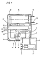
- the relay according to the invention consists of a cover 1 with a spring bracket 2, which has a contact carrier 3, which has three pieces of clamping screws 4 and three pieces of hollow terminals 5.
- the contact carrier 3 consists at its upper part of a bent metal bracket which merges into a fixed contact 6.
- switching spring 9 which is designed as a bridge contact, i.e. it is always in contact with a fixed center contact, the bridge spring is arranged at the free end of a stamped part 10 and sits with its foot piece in a rocker 11 which is pivotally fastened in a bearing plate 12 which is riveted to the magnetic part.
- an outer, circumferential bracket 13 made of plastic is provided.
- a relay coil 14 with connections 15 and 16.
- the relay coil 14 acts on two yoke plates 17.38.
- the rocker 11 is extended via a handle 18 and extends through a corresponding recess 19 in the cover 1, so that it can be operated manually.
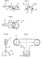
- the rocker preferably consists of a plastic part with an elongated plate 20 into which an opening 21 is embedded.
- the changeover spring 9 is seated with a foot piece 22 made of insulating material. It is important here that the stamped part 10 is completely surrounded by the plastic material and the changeover spring 9 is introduced into the recess 21 on the rocker 11 by a rotary movement.
- the rotary movement is in the direction of arrow 23, and the foot piece is inserted into this recess in the manner of a bayonet coupling.
- the recess is provided with an undercut 24 in which the foot piece 22 of the changeover spring engages.
- the undercut 24 is shown enlarged in FIG. 6 and is shown in more detail there.
- the rocker 11 also consists of two lateral bearing arms 25 and 26; outwardly projecting bearing bolts 27, 28 are arranged on each bearing arm.
- each bearing arm Arranged lugs 29,30, the function of which will be described later.
- an anchor plate 32 is arranged behind the foot piece 22 in the area on the rear of the bearing plate 20 of the rocker 11, in which holes are arranged which are arranged on correspondingly arranged locking pins 33, 34 the plate 20 rests.
- a permanent magnet 35 is attached to the back of the bearing plate 20, which in turn is held by a double-T-shaped anchor plate 36 from the back.
- the anchor plates 32, 36 are exactly the same.
- the anchor plate 36 is held by the locking lugs 29, 30 of the rocker 11.
- the magnet 35 and the first armature plate 32 are thus axially braced against the changeover spring 9.
- the locking lugs 29, 30 are snapped onto the corresponding bearing plate 36 with their locking openings.
- the bearing bolts 27, 28 and the undercut 24 can be seen in the region of the recess 21.
- the changeover spring is shown in more detail in FIGS. 7 and 8. It is important that there are lower projections 37 in the foot piece 22, which engage in a rotary movement in the undercuts 24, which are circular in the area of the recess 21.
- the entire switching spring is secured against radial rotation and the axial displacement protection is effected by the bearing plate 32 arranged behind it with the magnet 35 and the further bearing plate 36, which cooperates with the latching lugs 29, 30.
- the version with a bistable relay has the additional advantage that the mounting of the anchor plates and the permanent magnet is very simple.
- this relay can also be designed with a make contact, the external contact carriers are then bridged with the contact bridge.
- the contact distance therefore doubles compared to the one-time switchover variant.
Landscapes
- Physics & Mathematics (AREA)
- Electromagnetism (AREA)
- Electromagnets (AREA)
- Relay Circuits (AREA)
- Percussive Tools And Related Accessories (AREA)
- Arc-Extinguishing Devices That Are Switches (AREA)
Priority Applications (1)
| Application Number | Priority Date | Filing Date | Title |
|---|---|---|---|
| AT84107230T ATE44113T1 (de) | 1983-06-28 | 1984-06-23 | Elektromagnetisches relais mit umschaltfeder. |
Applications Claiming Priority (2)
| Application Number | Priority Date | Filing Date | Title |
|---|---|---|---|
| DE3323266A DE3323266C2 (de) | 1983-06-28 | 1983-06-28 | Elektromagnetisches Relais mit Umschaltfeder |
| DE3323266 | 1983-06-28 |
Publications (3)
| Publication Number | Publication Date |
|---|---|
| EP0130511A2 true EP0130511A2 (fr) | 1985-01-09 |
| EP0130511A3 EP0130511A3 (en) | 1986-10-01 |
| EP0130511B1 EP0130511B1 (fr) | 1989-06-14 |
Family
ID=6202597
Family Applications (1)
| Application Number | Title | Priority Date | Filing Date |
|---|---|---|---|
| EP84107230A Expired EP0130511B1 (fr) | 1983-06-28 | 1984-06-23 | Relais électromagnétique avec un ressort de contact inverseur |
Country Status (4)
| Country | Link |
|---|---|
| US (1) | US4620172A (fr) |
| EP (1) | EP0130511B1 (fr) |
| AT (1) | ATE44113T1 (fr) |
| DE (2) | DE3323266C2 (fr) |
Cited By (2)
| Publication number | Priority date | Publication date | Assignee | Title |
|---|---|---|---|---|
| FR2758412A1 (fr) * | 1997-01-14 | 1998-07-17 | Schneider Electric Sa | Appareil interrupteur electromagnetique |
| US11731391B2 (en) | 2019-05-23 | 2023-08-22 | Awi Licensing Llc | Fire resistant low density acoustic panel |
Families Citing this family (3)
| Publication number | Priority date | Publication date | Assignee | Title |
|---|---|---|---|---|
| US6084488A (en) * | 1998-04-03 | 2000-07-04 | Pass & Seymour, Inc. | Compact high current relay |
| DE102004018791A1 (de) * | 2004-04-15 | 2005-11-03 | Tyco Electronics Amp Gmbh | Relaisantrieb, Relais und Bausatz für monostabiles und bistabiles Relais |
| CN1321430C (zh) * | 2006-03-06 | 2007-06-13 | 通领科技集团有限公司 | 具有压力平衡自动补偿的接地故障断路器动作机构 |
Family Cites Families (13)
| Publication number | Priority date | Publication date | Assignee | Title |
|---|---|---|---|---|
| US306874A (en) * | 1884-10-21 | Carriage-top prop | ||
| US402132A (en) * | 1889-04-30 | Albert g | ||
| DE901216C (de) * | 1951-11-30 | 1954-01-07 | Mix & Genest Ag | Relais, dessen Kontaktfedersatz aus nicht vorgespannten Kontaktfedern besteht |
| NL94917C (fr) * | 1957-02-28 | |||
| US2896045A (en) * | 1957-11-08 | 1959-07-21 | American Nat Bank | Relay with clamp-contact assembly |
| US3295078A (en) * | 1964-12-16 | 1966-12-27 | Guardian Electric Mfg Company | Relay |
| US3470504A (en) * | 1967-09-15 | 1969-09-30 | Henry Rogers Mallory | Polarized electrical relay |
| JPS538901B2 (fr) * | 1971-09-01 | 1978-04-01 | ||
| US4259652A (en) * | 1979-04-30 | 1981-03-31 | Eltra Corporation | Reversing relay for permanent magnet DC motor |
| FR2486303A1 (fr) * | 1980-03-21 | 1982-01-08 | Bernier Et Cie Ets | Relais electromagnetique a armature pivotante a aimant permanent |
| DE3021184A1 (de) * | 1980-06-04 | 1982-02-04 | E. Haller & Co, 7209 Wehingen | Relais zum schalten hoher stroeme |
| DE3118292C2 (de) * | 1981-05-08 | 1983-02-10 | Siemens AG, 1000 Berlin und 8000 München | Elektromagnetisches Relais |
| DE8235283U1 (de) * | 1982-12-15 | 1983-06-09 | Siemens AG, 1000 Berlin und 8000 München | Elektromagnetisches Relais |
-
1983
- 1983-06-28 DE DE3323266A patent/DE3323266C2/de not_active Expired
-
1984
- 1984-06-23 AT AT84107230T patent/ATE44113T1/de not_active IP Right Cessation
- 1984-06-23 EP EP84107230A patent/EP0130511B1/fr not_active Expired
- 1984-06-23 DE DE8484107230T patent/DE3478728D1/de not_active Expired
- 1984-06-25 US US06/624,255 patent/US4620172A/en not_active Expired - Fee Related
Cited By (3)
| Publication number | Priority date | Publication date | Assignee | Title |
|---|---|---|---|---|
| FR2758412A1 (fr) * | 1997-01-14 | 1998-07-17 | Schneider Electric Sa | Appareil interrupteur electromagnetique |
| EP0854489A1 (fr) * | 1997-01-14 | 1998-07-22 | Schneider Electric Sa | Appareil interrupteur électromagnétique |
| US11731391B2 (en) | 2019-05-23 | 2023-08-22 | Awi Licensing Llc | Fire resistant low density acoustic panel |
Also Published As
| Publication number | Publication date |
|---|---|
| EP0130511A3 (en) | 1986-10-01 |
| DE3478728D1 (en) | 1989-07-20 |
| EP0130511B1 (fr) | 1989-06-14 |
| ATE44113T1 (de) | 1989-06-15 |
| DE3323266A1 (de) | 1985-01-10 |
| US4620172A (en) | 1986-10-28 |
| DE3323266C2 (de) | 1987-01-02 |
Similar Documents
| Publication | Publication Date | Title |
|---|---|---|
| DE3336207C3 (de) | Elektrischer Schalter mit Anschlag des Steuerhebels bei Zusammenschweissen der Kontakte | |
| EP0868735B1 (fr) | Unite d'appareillage de commutation | |
| EP0792985B1 (fr) | Gâche électrique | |
| DE6609020U (de) | Schaltschuetz. | |
| DE4423277B4 (de) | Leistungsschalter mit gemeinsamem Auslösemechanismus | |
| DE9203532U1 (de) | Mechanischer Umschalt-, Parallel- oder Fernantrieb für elektrische Schaltgeräte mit Dreh- oder Kipphebelantrieb, insbesondere für Leistungstrenner, Motorschutzschalter und dergleichen | |
| DE2022941C3 (de) | Elektromagnetische Zentralver- und Entriegelungseinrichtung für die Türverschlüsse eines Kraftfahrzeuges | |
| EP0130511A2 (fr) | Relais électromagnétique avec un ressort de contact inverseur | |
| EP0867030B1 (fr) | Appareil commutateur | |
| EP0483697A1 (fr) | Verrouillage magnétique | |
| DE2821901C2 (de) | Türschloß für ein Fahrzeug | |
| EP0188482B1 (fr) | Verrou de commutation | |
| EP0003967B1 (fr) | Dispositif de loquet pour un interrupteur de puissance | |
| CH690345A5 (de) | Abgedichteter elektrischer Schalter und Schalteranordnung. | |
| DE3443556C2 (de) | Elektrisches Schaltgerät | |
| DE3348068C2 (en) | Electromagnetic relay whose changeover spring has a special construction | |
| DE3513803C2 (fr) | ||
| DE2853027A1 (de) | Elektrischer tueroeffner | |
| DE19803648A1 (de) | Elektromagnetisch steuerbares Sicherheitsschloß | |
| AT268428B (de) | Elektrisches Schütz | |
| DE1790119C3 (fr) | ||
| DE2036482C3 (de) | Elektromagnetisches Schütz | |
| EP0105516B1 (fr) | Agencement de commutateur | |
| DE3425996C2 (fr) | ||
| DE1590605C (de) | Als Dreh oder Schiebeschalter ausgebildeter Stufenschalter |
Legal Events
| Date | Code | Title | Description |
|---|---|---|---|
| PUAI | Public reference made under article 153(3) epc to a published international application that has entered the european phase |
Free format text: ORIGINAL CODE: 0009012 |
|
| AK | Designated contracting states |
Designated state(s): AT BE CH DE FR GB IT LI LU NL SE |
|
| PUAL | Search report despatched |
Free format text: ORIGINAL CODE: 0009013 |
|
| AK | Designated contracting states |
Kind code of ref document: A3 Designated state(s): AT BE CH DE FR GB IT LI LU NL SE |
|
| 17P | Request for examination filed |
Effective date: 19861114 |
|
| 17Q | First examination report despatched |
Effective date: 19880621 |
|
| GRAA | (expected) grant |
Free format text: ORIGINAL CODE: 0009210 |
|
| AK | Designated contracting states |
Kind code of ref document: B1 Designated state(s): AT BE CH DE FR GB IT LI LU NL SE |
|
| PG25 | Lapsed in a contracting state [announced via postgrant information from national office to epo] |
Ref country code: SE Effective date: 19890614 Ref country code: NL Effective date: 19890614 Ref country code: BE Effective date: 19890614 |
|
| REF | Corresponds to: |
Ref document number: 44113 Country of ref document: AT Date of ref document: 19890615 Kind code of ref document: T |
|
| ITTA | It: last paid annual fee | ||
| PG25 | Lapsed in a contracting state [announced via postgrant information from national office to epo] |
Ref country code: LU Free format text: LAPSE BECAUSE OF NON-PAYMENT OF DUE FEES Effective date: 19890630 |
|
| REF | Corresponds to: |
Ref document number: 3478728 Country of ref document: DE Date of ref document: 19890720 |
|
| ITF | It: translation for a ep patent filed | ||
| GBT | Gb: translation of ep patent filed (gb section 77(6)(a)/1977) | ||
| ET | Fr: translation filed | ||
| NLV1 | Nl: lapsed or annulled due to failure to fulfill the requirements of art. 29p and 29m of the patents act | ||
| GBPC | Gb: european patent ceased through non-payment of renewal fee | ||
| PLBE | No opposition filed within time limit |
Free format text: ORIGINAL CODE: 0009261 |
|
| STAA | Information on the status of an ep patent application or granted ep patent |
Free format text: STATUS: NO OPPOSITION FILED WITHIN TIME LIMIT |
|
| 26N | No opposition filed | ||
| PGFP | Annual fee paid to national office [announced via postgrant information from national office to epo] |
Ref country code: FR Payment date: 19900626 Year of fee payment: 7 |
|
| PGFP | Annual fee paid to national office [announced via postgrant information from national office to epo] |
Ref country code: AT Payment date: 19900629 Year of fee payment: 7 |
|
| PGFP | Annual fee paid to national office [announced via postgrant information from national office to epo] |
Ref country code: DE Payment date: 19900630 Year of fee payment: 7 |
|
| REG | Reference to a national code |
Ref country code: GB Ref legal event code: 728C |
|
| PGFP | Annual fee paid to national office [announced via postgrant information from national office to epo] |
Ref country code: CH Payment date: 19900831 Year of fee payment: 7 |
|
| REG | Reference to a national code |
Ref country code: GB Ref legal event code: 210A |
|
| PGFP | Annual fee paid to national office [announced via postgrant information from national office to epo] |
Ref country code: GB Payment date: 19910617 Year of fee payment: 8 |
|
| PG25 | Lapsed in a contracting state [announced via postgrant information from national office to epo] |
Ref country code: AT Effective date: 19910623 |
|
| PG25 | Lapsed in a contracting state [announced via postgrant information from national office to epo] |
Ref country code: LI Effective date: 19910630 Ref country code: CH Effective date: 19910630 |
|
| PG25 | Lapsed in a contracting state [announced via postgrant information from national office to epo] |
Ref country code: FR Effective date: 19920228 |
|
| REG | Reference to a national code |
Ref country code: CH Ref legal event code: PL |
|
| PG25 | Lapsed in a contracting state [announced via postgrant information from national office to epo] |
Ref country code: DE Effective date: 19920401 |
|
| REG | Reference to a national code |
Ref country code: FR Ref legal event code: ST |
|
| PG25 | Lapsed in a contracting state [announced via postgrant information from national office to epo] |
Ref country code: GB Effective date: 19920623 |
|
| GBPC | Gb: european patent ceased through non-payment of renewal fee |
Effective date: 19920623 |