EP0130567A2 - Couverture pour piscines - Google Patents
Couverture pour piscines Download PDFInfo
- Publication number
- EP0130567A2 EP0130567A2 EP84107460A EP84107460A EP0130567A2 EP 0130567 A2 EP0130567 A2 EP 0130567A2 EP 84107460 A EP84107460 A EP 84107460A EP 84107460 A EP84107460 A EP 84107460A EP 0130567 A2 EP0130567 A2 EP 0130567A2
- Authority
- EP
- European Patent Office
- Prior art keywords
- hollow profile
- openings
- guide
- parts
- cover according
- Prior art date
- Legal status (The legal status is an assumption and is not a legal conclusion. Google has not performed a legal analysis and makes no representation as to the accuracy of the status listed.)
- Granted
Links
- 238000009423 ventilation Methods 0.000 claims abstract description 16
- 230000009182 swimming Effects 0.000 claims abstract description 4
- 210000003903 pelvic floor Anatomy 0.000 claims description 2
- 230000000284 resting effect Effects 0.000 claims 1
- 125000006850 spacer group Chemical group 0.000 claims 1
- 230000000630 rising effect Effects 0.000 abstract description 5
- XLYOFNOQVPJJNP-UHFFFAOYSA-N water Substances O XLYOFNOQVPJJNP-UHFFFAOYSA-N 0.000 description 12
- 230000009194 climbing Effects 0.000 description 1
- 230000002349 favourable effect Effects 0.000 description 1
- 229910001385 heavy metal Inorganic materials 0.000 description 1
- 229910052751 metal Inorganic materials 0.000 description 1
- 239000002184 metal Substances 0.000 description 1
- 238000000034 method Methods 0.000 description 1
- 210000004197 pelvis Anatomy 0.000 description 1
Images


Classifications
-
- E—FIXED CONSTRUCTIONS
- E04—BUILDING
- E04H—BUILDINGS OR LIKE STRUCTURES FOR PARTICULAR PURPOSES; SWIMMING OR SPLASH BATHS OR POOLS; MASTS; FENCING; TENTS OR CANOPIES, IN GENERAL
- E04H4/00—Swimming or splash baths or pools
- E04H4/06—Safety devices; Coverings for baths
- E04H4/10—Coverings of flexible material
- E04H4/103—Coverings of flexible material with inflatable chambers
Definitions
- the invention relates to a cover for pools, in particular swimming pools, consisting of hollow profile parts which have flooding openings at one end and ventilation openings at the other end, the ventilation openings being optionally connectable to the environment or a pressurized gas source and the hollow profile parts being attached to vertically running guide devices are guided on the pool.
- Such covers are described for example in DE 29 43 366 A and EP 0044 104 A.
- Guide devices for such covers are shown and described in EP 0044 104 A. According to a first embodiment, these are vertically tensioned ropes which are enclosed by eyelets on the hollow profile parts. The ropes are attached to the pool wall. The eyelets and therefore the ropes are located in the area of the cover where the hollow profile parts have the ventilation openings.
- These guiding devices are intended to position the cover within the basin. This first mentioned embodiment of guide devices does not serve its purpose. If air is introduced via the ventilation openings when the cover is lowered, the end face of the cover which has the ventilation openings rises relatively rapidly, while the opposite end side of the cover which has the flood openings still lies on the floor.
- the known covers are subject to further disadvantages which impair the rising and falling.
- the air is supplied and removed to the ventilation openings via pipes on the top of the hollow profile parts.
- An elastic hose is connected to these pipes, which is connected to a valve in the area of the pool edge. This hose can be clamped by the hollow profile parts when it rises and falls, thereby interrupting the rising or falling.
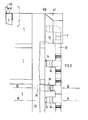
- the cover shown in Figures 1 and 2 consists of individual hollow profile parts 1 and 2.
- the interconnected hollow profile parts 1 form a first path 3 of the cover, while they also ver with each other bound hollow profile parts 2 form a second parallel path 4 of the cover.
- the two tracks 3, 4 can be lowered and raised independently of one another.
- the hollow profile parts 1 and 2 have on one end face 5 and 5 'flooding openings 6. Ventilation openings 8 are provided on the end face 7 or 7 'opposite the end face 5 or 5'.
- the cover lies on the bottom 9 of the basin. If compressed air is introduced into the interior of the hollow profile parts 1 or 2 via the openings 8, water emerges through the flooding openings 6 and the end face 7 or 7 'of the web 4 or 3 rises in an arc-shaped manner relatively quickly, as is the case with the web 10 in Fig. 1. In the last part of the upward movement, the end face 7 or 7 'jumps out of the water. During the first part of the ascent of the cover, a considerable area of the underside of the cover rests on the pelvic floor 9. With increasing introduction of air through the openings 8, the entire cover gradually rises to the water surface. The end face 5 executes a considerably slower vertical movement than is the case with the end face 7.
- the openings 8 are connected to the surroundings, as a result of which the air in the hollow profiles can flow out through the openings 8, while at the same time water 6 penetrates into the interior of the hollow profile parts 1, 2 via the flooding openings.
- the front side 5 lowers first and at the end of the lowering movement the front side 7.
- the guide rail 12 has a T-profile.
- the guide part 13 is formed in two parts and consists of a guide head 14 U-shaped cross section with a connecting fork 15 which is articulated to a fastening bolt 16.
- the connection between the parts 15 and 16 represents an articulated connection with a horizontally extending articulated axis 17.
- the fastening bolt 16 is screwed with its threaded end into a threaded bore 18 on the end face 5 and fixed there by a lock nut 19.
- the articulated connection between the parts 15 and 16 ensures that the cover is able to assume a position when rising and falling, as shown in broken lines in FIG. 1. Due to the screwing depth of the two fastening bolts 16 per lane 3 or 4, it is possible to align the lanes 3 and 4 precisely with the longitudinal sides 20 of the basin.
- the guide rail consists of a tube of circular cross section, which has a longitudinal slot 21 in the direction of the end face 5.
- the fastening bolt 16 ' ends in a ball head 22 which is mounted in the interior of the tube.
- An articulated guide thus results between the ball head 22 and the tube a horizontal hinge axis 17 '.
- the tubular guide rail acc. 4 can also have an inner cross section that deviates from the circular shape.
- the head 22 can also have a shape that deviates from the spherical shape. However, it must always be ensured that the joint guide has a horizontal joint axis 17 '.
- the guide rails 12 can also have a U-profile and the guide parts 13 each carry two horizontally mounted rollers which engage in the respective U-profile in accordance with the mounting of a sliding door. This is illustrated by FIGS. 5 to 7.
- the guide rail acc. 5 to 7 has a U-shaped cross section. Two pairs of rollers 26 are guided in this rail and are supported by a carrier 27. A connecting fork 15, which carries the fastening bolt 16, is fastened to this support 27 so as to be pivotable about the horizontal axis 17.
- a plate 23 is firmly screwed to the basin wall 11, which carries two bolts 24.
- the guide rail 12 has two lateral webs 25, each of which has a bore and which can be plugged onto the screw bolts 24 by means of these bores. The distance between the guide rail 12 and the pool wall 11 can thus be adjusted by two nuts per screw bolt 24.
- FIG. 7 shows a section through the end face 5 of a hollow profile part 1 which has the flooding openings 6.
- closure parts are inserted on the end face, which carry a pipe socket 31.
- An angled tube 32 is placed on this pipe socket 31.
- This end of the hollow profile part 1 is overlapped by a U-shaped end profile part 28, which consists of plastic and has an opening for the part 32.
- a metal plate 33 into which the fastening bolt 16 is screwed, is inserted at the end face into this end profile part 28.
- a rectangular profile part 29 is screwed to the hollow profile part 1 and the end profile part 28, inside which wires 30 made of heavy metal are inserted, thereby accelerating the lowering process.
- the end face 7 which has the ventilation openings 8 is explained below with reference to FIGS. 8 to 10.
- Each hollow profile part 1 is closed at the end by an end plate 35 having a pipe socket 34.
- a piece of pipe runs from each pipe socket 34 36 obliquely upwards to a distributor pipe 37 which extends over the level of the hollow profile parts 1 over its entire length.
- a distributor pipe 37 which extends over the level of the hollow profile parts 1 over its entire length.
- another pipe section 38 runs obliquely downwards, which ends in a pipe socket 39, which runs below the hollow profile parts 1 and to which an elastic hose is connected, which leads to the pool floor.
- This pipeline system is covered by a further end profile part 40, which is also made of plastic and which only has an opening for the pipe section 38.
- this end profile part 40 is provided with a bevel 41 which, in cooperation with an equal bevel of the adjacent tracks 3, 4, prevents the two tracks 3, 4 from sliding on one another when the tracks rise or fall.
- the edges of the hollow profile parts 1, 2 are not flush with the adjacent pool wall, but it is often desired that the entire water surface of the pool is covered, the edges can be provided with an elastic lip 43, which the distance between the edge of a hollow profile part and bridged the associated pool wall.
- the lip 43 which runs approximately flush with the surface of the hollow profile parts 1, 2, can in this case be arranged on a U-shaped profile 42 which is placed over the edge of a hollow profile part.
- a hinge 44 can be provided between the lip 43 and the U-profile. This applies in particular especially when the pool walls run diagonally downwards.
- This lip 43 is illustrated in a sectional view in FIG. 8.
Landscapes
- Engineering & Computer Science (AREA)
- Architecture (AREA)
- Civil Engineering (AREA)
- Structural Engineering (AREA)
- Materials Applied To Surfaces To Minimize Adherence Of Mist Or Water (AREA)
- Tents Or Canopies (AREA)
- Bathtub Accessories (AREA)
- Devices For Medical Bathing And Washing (AREA)
Priority Applications (1)
| Application Number | Priority Date | Filing Date | Title |
|---|---|---|---|
| AT84107460T ATE42790T1 (de) | 1983-07-05 | 1984-06-28 | Abdeckung fuer becken. |
Applications Claiming Priority (2)
| Application Number | Priority Date | Filing Date | Title |
|---|---|---|---|
| DE3324150A DE3324150A1 (de) | 1983-07-05 | 1983-07-05 | Abdeckung fuer becken |
| DE3324150 | 1983-07-05 |
Publications (3)
| Publication Number | Publication Date |
|---|---|
| EP0130567A2 true EP0130567A2 (fr) | 1985-01-09 |
| EP0130567A3 EP0130567A3 (en) | 1986-11-26 |
| EP0130567B1 EP0130567B1 (fr) | 1989-05-03 |
Family
ID=6203167
Family Applications (1)
| Application Number | Title | Priority Date | Filing Date |
|---|---|---|---|
| EP84107460A Expired EP0130567B1 (fr) | 1983-07-05 | 1984-06-28 | Couverture pour piscines |
Country Status (3)
| Country | Link |
|---|---|
| EP (1) | EP0130567B1 (fr) |
| AT (1) | ATE42790T1 (fr) |
| DE (2) | DE3324150A1 (fr) |
Family Cites Families (7)
| Publication number | Priority date | Publication date | Assignee | Title |
|---|---|---|---|---|
| US3469587A (en) * | 1967-12-22 | 1969-09-30 | Foldway Covers Ltd | Collapsible weatherproof cover for swimming pools |
| US3668711A (en) * | 1971-01-21 | 1972-06-13 | Charles J Liermann | Swimming pool cover and rescue device |
| US3813704A (en) * | 1972-06-19 | 1974-06-04 | D Troiano | Floatable safety cover for swimming pools |
| DE7436960U (de) * | 1974-11-06 | 1977-12-29 | Nitzsche, Heinz, 3014 Laatzen | Vorrichtung zum abdecken eines eine fluessigkeit enthaltenden beckens, insbesondere schwimmbeckens |
| US4129905A (en) * | 1977-06-30 | 1978-12-19 | Jerzy Niemirow | Swimming pool rescue net |
| DE2943366C2 (de) * | 1979-10-26 | 1983-10-06 | Gustav 8922 Peiting Stifter | Absenkbare und begehbare Abdeckung für Flüssigkeitsbehälter, insbesondere für Schwimmbecken |
| AT370481B (de) * | 1980-07-09 | 1983-04-11 | Dipl Ing Dr Tech Heinz Sernetz | Abdeckung fuer ein mit fluessigkeit gefuelltes becken |
-
1983
- 1983-07-05 DE DE3324150A patent/DE3324150A1/de not_active Withdrawn
-
1984
- 1984-06-28 DE DE8484107460T patent/DE3478042D1/de not_active Expired
- 1984-06-28 AT AT84107460T patent/ATE42790T1/de not_active IP Right Cessation
- 1984-06-28 EP EP84107460A patent/EP0130567B1/fr not_active Expired
Also Published As
| Publication number | Publication date |
|---|---|
| DE3324150A1 (de) | 1985-01-17 |
| EP0130567A3 (en) | 1986-11-26 |
| DE3478042D1 (en) | 1989-06-08 |
| EP0130567B1 (fr) | 1989-05-03 |
| ATE42790T1 (de) | 1989-05-15 |
Similar Documents
| Publication | Publication Date | Title |
|---|---|---|
| EP0163292B1 (fr) | Barrage pour la protection contre les crues | |
| DE2619931A1 (de) | Falschdecke oder blendwand | |
| CH660896A5 (de) | Fahrbahn-abschrankungsstrecke. | |
| DE2935745C2 (de) | Lärmschutzwand | |
| DE9013861U1 (de) | Tauchwand für Regen- und Klärbecken | |
| DE102011119697A1 (de) | Duschsystem | |
| DE3529877C1 (en) | Apparatus for bridging expansion joints | |
| DE2808270A1 (de) | Foerderer sowie querschwelle dafuer | |
| DE2611323A1 (de) | Einstellvorrichtung | |
| EP0130567B1 (fr) | Couverture pour piscines | |
| DE102005019034B4 (de) | Verbauvorrichtung | |
| DE69613744T2 (de) | Schutzvorrichtung zum Verhindern des Eindringens von Wasser in eine Wand und zum Verbessern des Abführens von Wasser aus einer Wand | |
| DE2912126C2 (de) | Bade- oder Duschwannenabtrennung in Form eines festen Rahmens und einer Schiebetür aus mehreren, in parallelen Ebenen horizontal bewegbaren Türelementen | |
| DE1908981A1 (de) | Entwaesserungseinrichtung fuer Sportanlagen | |
| DE2321925A1 (de) | Schalungstraeger | |
| DE3334481A1 (de) | In der hoehe verstellbares waschbecken | |
| DE3124557A1 (de) | Gelaender aus korrosionsbestaendigem stahl | |
| AT3921U1 (de) | Mehrzweckschutzumzäunung, insbesondere zur absicherung von strassenbaustellen und zum schutz der fahrbahn gegen wind und schneeverwehung | |
| DE9104764U1 (de) | Wassereindringschutz für Sanitärarmaturen | |
| DE7921329U1 (de) | Vorrichtung zur stufenlos vertikal einrichtbaren halterung einer dusche bzw. handbrause o.dgl. an einer wand | |
| DE10231771B4 (de) | Vorrichtung zur Auflagerung von Kranbahnen | |
| DE9116144U1 (de) | Installationsblock | |
| DE102006006919B4 (de) | Mobile Schutzwand-Vorrichtung | |
| DE955631C (de) | Vorrichtung zur kittlosen Befestigung von Glasabdeckungen auf Stahlbetontragkoerpern | |
| DE1908978A1 (de) | Aufhaengevorrichtung fuer verschiebbare Tueren und Waende |
Legal Events
| Date | Code | Title | Description |
|---|---|---|---|
| PUAI | Public reference made under article 153(3) epc to a published international application that has entered the european phase |
Free format text: ORIGINAL CODE: 0009012 |
|
| AK | Designated contracting states |
Designated state(s): AT CH DE FR LI NL |
|
| PUAL | Search report despatched |
Free format text: ORIGINAL CODE: 0009013 |
|
| AK | Designated contracting states |
Kind code of ref document: A3 Designated state(s): AT CH DE FR LI NL |
|
| 17P | Request for examination filed |
Effective date: 19870512 |
|
| RAP1 | Party data changed (applicant data changed or rights of an application transferred) |
Owner name: SYTEK DICHTUNGSSYSTEME WAEDENSWIL AG |
|
| 17Q | First examination report despatched |
Effective date: 19880920 |
|
| GRAA | (expected) grant |
Free format text: ORIGINAL CODE: 0009210 |
|
| RAP1 | Party data changed (applicant data changed or rights of an application transferred) |
Owner name: PEREFINA AG |
|
| AK | Designated contracting states |
Kind code of ref document: B1 Designated state(s): AT CH DE FR LI NL |
|
| REF | Corresponds to: |
Ref document number: 42790 Country of ref document: AT Date of ref document: 19890515 Kind code of ref document: T |
|
| REF | Corresponds to: |
Ref document number: 3478042 Country of ref document: DE Date of ref document: 19890608 |
|
| ET | Fr: translation filed | ||
| PLBE | No opposition filed within time limit |
Free format text: ORIGINAL CODE: 0009261 |
|
| STAA | Information on the status of an ep patent application or granted ep patent |
Free format text: STATUS: NO OPPOSITION FILED WITHIN TIME LIMIT |
|
| 26N | No opposition filed | ||
| PGFP | Annual fee paid to national office [announced via postgrant information from national office to epo] |
Ref country code: NL Payment date: 19910630 Year of fee payment: 8 |
|
| PGFP | Annual fee paid to national office [announced via postgrant information from national office to epo] |
Ref country code: CH Payment date: 19910723 Year of fee payment: 8 |
|
| PGFP | Annual fee paid to national office [announced via postgrant information from national office to epo] |
Ref country code: AT Payment date: 19910731 Year of fee payment: 8 |
|
| PGFP | Annual fee paid to national office [announced via postgrant information from national office to epo] |
Ref country code: FR Payment date: 19911029 Year of fee payment: 8 |
|
| PG25 | Lapsed in a contracting state [announced via postgrant information from national office to epo] |
Ref country code: AT Effective date: 19920628 |
|
| PG25 | Lapsed in a contracting state [announced via postgrant information from national office to epo] |
Ref country code: LI Effective date: 19920630 Ref country code: CH Effective date: 19920630 |
|
| PG25 | Lapsed in a contracting state [announced via postgrant information from national office to epo] |
Ref country code: NL Effective date: 19930101 |
|
| NLV4 | Nl: lapsed or anulled due to non-payment of the annual fee | ||
| PGFP | Annual fee paid to national office [announced via postgrant information from national office to epo] |
Ref country code: DE Payment date: 19930220 Year of fee payment: 9 |
|
| PG25 | Lapsed in a contracting state [announced via postgrant information from national office to epo] |
Ref country code: FR Effective date: 19930226 |
|
| REG | Reference to a national code |
Ref country code: CH Ref legal event code: PL |
|
| REG | Reference to a national code |
Ref country code: FR Ref legal event code: ST |
|
| PG25 | Lapsed in a contracting state [announced via postgrant information from national office to epo] |
Ref country code: DE Effective date: 19940301 |