EP0130583B1 - Structure composite à noyau épais et procédé de fabrication - Google Patents
Structure composite à noyau épais et procédé de fabrication Download PDFInfo
- Publication number
- EP0130583B1 EP0130583B1 EP84107509A EP84107509A EP0130583B1 EP 0130583 B1 EP0130583 B1 EP 0130583B1 EP 84107509 A EP84107509 A EP 84107509A EP 84107509 A EP84107509 A EP 84107509A EP 0130583 B1 EP0130583 B1 EP 0130583B1
- Authority
- EP
- European Patent Office
- Prior art keywords
- face
- core
- sheets
- sheet
- nodes
- Prior art date
- Legal status (The legal status is an assumption and is not a legal conclusion. Google has not performed a legal analysis and makes no representation as to the accuracy of the status listed.)
- Expired - Lifetime
Links
- 238000004519 manufacturing process Methods 0.000 title description 6
- 238000009792 diffusion process Methods 0.000 claims description 22
- 238000000034 method Methods 0.000 claims description 20
- 229910052751 metal Inorganic materials 0.000 claims description 13
- 239000002184 metal Substances 0.000 claims description 13
- 230000001154 acute effect Effects 0.000 claims description 5
- 239000011162 core material Substances 0.000 description 113
- 238000005304 joining Methods 0.000 description 7
- 239000011261 inert gas Substances 0.000 description 6
- 229910045601 alloy Inorganic materials 0.000 description 5
- 239000000956 alloy Substances 0.000 description 5
- 239000000463 material Substances 0.000 description 5
- 230000004927 fusion Effects 0.000 description 4
- 238000003466 welding Methods 0.000 description 4
- 229910001069 Ti alloy Inorganic materials 0.000 description 3
- 239000007789 gas Substances 0.000 description 3
- 229910001092 metal group alloy Inorganic materials 0.000 description 3
- XKRFYHLGVUSROY-UHFFFAOYSA-N Argon Chemical compound [Ar] XKRFYHLGVUSROY-UHFFFAOYSA-N 0.000 description 2
- PXHVJJICTQNCMI-UHFFFAOYSA-N Nickel Chemical compound [Ni] PXHVJJICTQNCMI-UHFFFAOYSA-N 0.000 description 2
- RTAQQCXQSZGOHL-UHFFFAOYSA-N Titanium Chemical compound [Ti] RTAQQCXQSZGOHL-UHFFFAOYSA-N 0.000 description 2
- 229910052782 aluminium Inorganic materials 0.000 description 2
- XAGFODPZIPBFFR-UHFFFAOYSA-N aluminium Chemical compound [Al] XAGFODPZIPBFFR-UHFFFAOYSA-N 0.000 description 2
- 230000035945 sensitivity Effects 0.000 description 2
- 239000007787 solid Substances 0.000 description 2
- 239000010936 titanium Substances 0.000 description 2
- 229910052719 titanium Inorganic materials 0.000 description 2
- RUDFQVOCFDJEEF-UHFFFAOYSA-N yttrium(III) oxide Inorganic materials [O-2].[O-2].[O-2].[Y+3].[Y+3] RUDFQVOCFDJEEF-UHFFFAOYSA-N 0.000 description 2
- 229910000838 Al alloy Inorganic materials 0.000 description 1
- 229910052582 BN Inorganic materials 0.000 description 1
- PZNSFCLAULLKQX-UHFFFAOYSA-N Boron nitride Chemical compound N#B PZNSFCLAULLKQX-UHFFFAOYSA-N 0.000 description 1
- OKTJSMMVPCPJKN-UHFFFAOYSA-N Carbon Chemical compound [C] OKTJSMMVPCPJKN-UHFFFAOYSA-N 0.000 description 1
- 241000257303 Hymenoptera Species 0.000 description 1
- ZOKXTWBITQBERF-UHFFFAOYSA-N Molybdenum Chemical compound [Mo] ZOKXTWBITQBERF-UHFFFAOYSA-N 0.000 description 1
- QCWXUUIWCKQGHC-UHFFFAOYSA-N Zirconium Chemical compound [Zr] QCWXUUIWCKQGHC-UHFFFAOYSA-N 0.000 description 1
- 229910052786 argon Inorganic materials 0.000 description 1
- 229910052790 beryllium Inorganic materials 0.000 description 1
- ATBAMAFKBVZNFJ-UHFFFAOYSA-N beryllium atom Chemical compound [Be] ATBAMAFKBVZNFJ-UHFFFAOYSA-N 0.000 description 1
- 239000011230 binding agent Substances 0.000 description 1
- 230000001276 controlling effect Effects 0.000 description 1
- 230000002596 correlated effect Effects 0.000 description 1
- 230000000875 corresponding effect Effects 0.000 description 1
- 229910002804 graphite Inorganic materials 0.000 description 1
- 239000010439 graphite Substances 0.000 description 1
- 239000007788 liquid Substances 0.000 description 1
- 150000002739 metals Chemical class 0.000 description 1
- 238000003801 milling Methods 0.000 description 1
- 239000000203 mixture Substances 0.000 description 1
- 229910052750 molybdenum Inorganic materials 0.000 description 1
- 239000011733 molybdenum Substances 0.000 description 1
- 229910052759 nickel Inorganic materials 0.000 description 1
- 239000010955 niobium Substances 0.000 description 1
- GUCVJGMIXFAOAE-UHFFFAOYSA-N niobium atom Chemical compound [Nb] GUCVJGMIXFAOAE-UHFFFAOYSA-N 0.000 description 1
- 238000003825 pressing Methods 0.000 description 1
- 238000012216 screening Methods 0.000 description 1
- 238000007493 shaping process Methods 0.000 description 1
- 239000010935 stainless steel Substances 0.000 description 1
- 229910001220 stainless steel Inorganic materials 0.000 description 1
- 238000005482 strain hardening Methods 0.000 description 1
- 239000000126 substance Substances 0.000 description 1
- 229910052715 tantalum Inorganic materials 0.000 description 1
- GUVRBAGPIYLISA-UHFFFAOYSA-N tantalum atom Chemical compound [Ta] GUVRBAGPIYLISA-UHFFFAOYSA-N 0.000 description 1
- 229910052726 zirconium Inorganic materials 0.000 description 1
Images


Classifications
-
- B—PERFORMING OPERATIONS; TRANSPORTING
- B64—AIRCRAFT; AVIATION; COSMONAUTICS
- B64C—AEROPLANES; HELICOPTERS
- B64C1/00—Fuselages; Constructional features common to fuselages, wings, stabilising surfaces or the like
- B64C1/06—Frames; Stringers; Longerons ; Fuselage sections
- B64C1/08—Geodetic or other open-frame structures
-
- B—PERFORMING OPERATIONS; TRANSPORTING
- B21—MECHANICAL METAL-WORKING WITHOUT ESSENTIALLY REMOVING MATERIAL; PUNCHING METAL
- B21D—WORKING OR PROCESSING OF SHEET METAL OR METAL TUBES, RODS OR PROFILES WITHOUT ESSENTIALLY REMOVING MATERIAL; PUNCHING METAL
- B21D47/00—Making rigid structural elements or units, e.g. honeycomb structures
-
- B—PERFORMING OPERATIONS; TRANSPORTING
- B23—MACHINE TOOLS; METAL-WORKING NOT OTHERWISE PROVIDED FOR
- B23K—SOLDERING OR UNSOLDERING; WELDING; CLADDING OR PLATING BY SOLDERING OR WELDING; CUTTING BY APPLYING HEAT LOCALLY, e.g. FLAME CUTTING; WORKING BY LASER BEAM
- B23K20/00—Non-electric welding by applying impact or other pressure, with or without the application of heat, e.g. cladding or plating
- B23K20/18—Zonal welding by interposing weld-preventing substances between zones not to be welded
-
- B—PERFORMING OPERATIONS; TRANSPORTING
- B64—AIRCRAFT; AVIATION; COSMONAUTICS
- B64C—AEROPLANES; HELICOPTERS
- B64C1/00—Fuselages; Constructional features common to fuselages, wings, stabilising surfaces or the like
- B64C2001/0054—Fuselage structures substantially made from particular materials
- B64C2001/0081—Fuselage structures substantially made from particular materials from metallic materials
-
- Y—GENERAL TAGGING OF NEW TECHNOLOGICAL DEVELOPMENTS; GENERAL TAGGING OF CROSS-SECTIONAL TECHNOLOGIES SPANNING OVER SEVERAL SECTIONS OF THE IPC; TECHNICAL SUBJECTS COVERED BY FORMER USPC CROSS-REFERENCE ART COLLECTIONS [XRACs] AND DIGESTS
- Y02—TECHNOLOGIES OR APPLICATIONS FOR MITIGATION OR ADAPTATION AGAINST CLIMATE CHANGE
- Y02T—CLIMATE CHANGE MITIGATION TECHNOLOGIES RELATED TO TRANSPORTATION
- Y02T50/00—Aeronautics or air transport
- Y02T50/40—Weight reduction
Definitions
- the invention relates to a superplastically formed-metallurgically bonded sandwich structure having an odd number (at least three) of core sheets with portions of the core sheets being layered and unlayered, and a method of fabricating such structures.
- Diffusion bonding is a metallurgical bonding or joining of similar metallic parts which are pressed together at elevated temperatures and pressures. This causes deformation which results in intimate contact of the surfaces to be joined and subsequent diffusion of the atomic structure. A monolithic metallic piece is formed with joint strength equivalent to that of the parent metal. Diffusion bonding is accomplished entirely in the solid state.
- FIG. 16 of that patent involves a sandwich structure having four sheets (two parallel face sheets, and two core sheets).
- the two core sheets are diffusion bonded together over their entire length.
- the core sheets are fusion welded to the face sheets.
- the distance between the face nodes and the distance between the face sheets must be increased. This may result in an unstable structure when loads are applied between the face nodes.
- the core sheets must be of a thicker gauge to support heavier loads which may make the sandwich too heavy for practical use.
- Another disadvantage of this structure is that the fusion welds provide poor fatigue resistance, and also make the structure difficult to manufacture.
- a principal object of the present invention is to provide a method of making a metallic sandwich structure with a partially layered core that is superplastically formed and metallurgically bonded at substantially the same temperature and pressure conditions.
- the present invention provides a sandwich structure having a partially layered core.
- the face sheets may be substantially parallel, converging or diverging, substantially concentric, or may have one or more oblique portions.
- a metallic sandwich structure comprises:
- a metallic sandwich structure comprises:
- a metallic sandwich structure comprises:
- the core of the sandwich structure includes layered (where two parallel core sheets are bonded together between nodes) and unlayered portions.
- the core sheets of the structure are selectively joined to the face sheets and to each other.
- the point at which two or more sheets are joined is referred to as a "node".
- a "face node” occurs where a face sheet is joined to a core sheet.
- a "core node” occurs where a core sheet becomes joined to another core sheet.
- the layered portions are designed for principal support of the face sheets.
- the unlayered portions support the face sheets at points between layered portion face nodes and also provide transverse support to the layered portions.
- Metallurgical bonding includes diffusion bonding, fusion welding, pressure welding, and similar processes.
- Diffusion bonding involves the solid state joining of metal surfaces by applying sufficient heat and pressure for a time that causes commingling of the molecules at the joint interface.
- Fusion welding involves the joining of metal surfaces by applying sufficient heat to cause the joint interface to reach the liquid state and merge into a unified whole.
- Pressure welding involves the joining of metal surfaces by applying pressure to cause commingling of the molecules at the joint interface.
- the core comprises a thick portion and a thin portion.
- the thick portion consists of core sheets that are bonded together to form layers.
- the thin portions are unlayered. Since in this embodiment all of the core sheets are the same material and the same gauge, the thick portions are stronger than the thin portions.
- the preferred method of metallurgical bonding is diffusion bonding.
- One reason for this preference is that the bond does not result in an excess of material at the joined interface.
- Another reason is that the diffusion bonding temperature and pressure ranges, closely match the superplastic forming temperatures and pressures.
- the forming process which includes the bonding and the expansion occurs in what is essentially a single step. Hence, the process need only use one heat cycle with the bonding and expansion occurring in the same apparatus.
- Diffusion bonding normally involves the treating of selected areas of the core sheets with a maskant prior to positioning said sheets in a stack. The areas where diffusion bonding is to occur are left exposed, whereas the maskant is applied to the remaining surface areas.
- the maskant may also be applied to face sheets in areas surrounding the face nodes.
- the expanded sandwich structure consisting of two face sheets and three core sheets is about 6.3 to 11.4 cm (2-1/2 to 4-1/2 inches) thick. To obtain a thicker sandwich with satisfactory strength properties more core sheets may be used.
- the angle between the core sheets and the face sheets is in the range of 50 to 65 degrees, and preferably about 60 degrees. If the angle is much greater than 65 degrees, the core sheets will be much closer together in the formed structure. Although this will improve the strength properties, the structure will be considerably heavier. If the angle is less than 50 degrees, the distance between the core sheets in the formed structure will be greater. Although this will result in a much lighter structure, the structure will not be able to support heavier transverse loads.
- This invention relates to the forming of thick metallic sandwich structures from a plurality of metal sheets having superplastic characteristics.
- the metallic alloys employed must have a composition and microstructure such that, when heated to a temperature within an appropriate temperature range and when deformed within an appropriate strain rate, they exhibit unusually high tensile elongations with reduced tendency towards necking.
- Such alloys can be represented by the formula.
- the value of "m” is a function of temperature, strain rate, microstructure, and material. Therefore, wide ranges in the value of "m” and the corresponding elongations can be developed for a given material as the rate of deformation changes. It has been found that in superplastic deformation under biaxial stress conditions, the uniformity of thinning is correlated to strain rate sensitivity. For use in the present invention a suitable strain rate is determined and this strain rate is controlled throughout the forming cycle to maintain sufficiently high values of "m” to minimize forming times, and to avoid rupture and excessive localized thinning.
- the alloys of titanium such as Ti-6AI-4V, and the alloys of aluminum are preferred.
- the superplastic temperature range for titanium alloys that is also suitable for diffusion bonding is generally 1450°F to 1850°F depending on the specific alloy used.
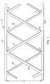
- FIG. 1 depicts an expanded sandwich structure of the subject invention generally indicated by Arrow 1 having a thick core, indicated by Dimension A.
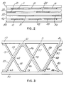
- Figures 3, 5, 6, 7, 9, and 11 show expanded sandwich structures with lines shown between the expanded bonded sheets. These lines are for purposes of illustration only.
- the expanded sandwich structure will have no lines between the expanded sheets because the metallurgical bonding will result in a formed homogeneous structure.
- the top face sheet 10 and the bottom face sheet 50 surround and sandwich the formed core sheets.
- the formed core sheets comprise layered core portions 16 that extend from the top face sheet 10 to the bottom face sheet 50 continuously throughout the entire length of the structure with joints at various face nodes 2, 3, and 4.
- the other core portions 18 are preferably not as thick as the layered core 16.
- Core portions 18 contact and support face sheets 10 and 50 and also contact and support layered core portions 16.
- Core potions 18 provide intermediate support to the layered portion face nodes, e.g., at nodes 5, 6, and 7, and additional transverse shear support to structure 1 while minimizing the weight penalty (by virtue of being relatively thin).
- Diffusion bonding which is the preferred method of metallurgical bonding, may be practiced in a wide variety of metal alloys, which include aluminum, stainless steel, titanium, nickel, tantalum, molybdenum, zirconium, columbium, and beryllium.
- a preferred step is to apply a maskant, that is also compatible with the metal sheets, to those areas of the sheets 10, 20, 30, 40, and 50 where no joining is required.
- the dark portions e.g., 11, 32, 22, and 43
- suitable mask- ants are graphite and boron nitride but yttria (Y 2 0 3 ), which is applied in a suitable binder by a silk screening process, is preferred.
- Both the upper and lower tooling frames are shaping members which combine to form the desired shaped structure.
- the sandwich structure is diverging, converging, concentric, or has oblique portions, the tooling members must have these overall general shapes.
- An inert gas line (not shown) is connected to pressurized inert gas and allows gas to flow through the stack into the upper tooling frame.
- the inert gas is preferably argon.
- the gas line can also be connected to a vacuum source for creating a vacuum in the stack.
- the pressurized inert gas compresses the stack because of the pressure differential between the stack interior and the chamber.
- the stack is heated in an inert gas atmosphere to about 1700°F, and a pressure differential is applied to the stack.
- a pressure differential of up to about 500 psi allows diffusion bonding of the sheets.
- the bonding time may vary from 30 minutes to 12 hours. After the bonding is complete, excess gas is removed from the chamber to allow for inflation of the stack.
- the face nodes on the top face sheet are 61, 71, and 81, and the face nodes on the bottom face sheet are 63, 73, 83, and 93.
- the core nodes are 62, 72, and 82.
- Truss eccentricity refers to the amount of deviation from linearity of the core sheets about the core nodes. Hence, eccentricity is eliminated when the core sheets are bonded together to form linear members through the core nodes. For example, core portion 15 and core portion 45 combine to form a substantially straight member through core node 62. Similarly, layered core portion 35 passes through core node 62 to form a substantially straight member with layered core portion 55. This core eccentricity can be eliminated or minimized by precisely controlling the selective application of the maskant, where diffusion bonding is used to join the core sheets 20, 30, and 40, together.
- the maskant must be applied such that (1) center core sheet 30 is selectively bonded to outer core sheets 20 and 40 to form core nodes (where three core sheets are joined) and layered portions (where the center core sheet is joined to only one outer core sheet between immediately succeeding core modes); (2) face nodes along each respective face sheet alternate the joining of layered and unlayered portions, i.e., at face node 61 layered portions 55 and 56 are joined to face sheet 10 while at face node 71 unlayered portions 57 and 58 are joined to face sheet 10; (3) opposite aligned face nodes, e.g., 61 and 73, have alternate joining of layered and unlayered portions, e.g., layered portions 55 and 56 are joined at face node 61 while unlayered portions 45 and 46 are joined at face node 73; and (4) between immediately successive core nodes and face nodes, there is either a layered portion or an unlayered portion, i.e., between core node 62 and face node 61 there is only
- FIG. 5 an enlarged view of a sandwich structure is depicted which has a core of substantially uniform thickness.
- FIG. 4 depicts how the sheets are to be stacked and the approximate locations of the maskant prior to diffusion bonding and superplastic forming.
- core sheets 37 and 38 are to be selectively processed prior to stacking by chemical milling or some similar process, so that sheets 37 and 38 have thick and thin portions.
- sheet 37 has thin portions 61 and 62 and thick portions 63 and 64.
- Sheets 37 and 38 must be thicker prior to processing than core sheet 30 and long strips are chemically milled along the length of sheets 37 and 38 that correspond to the thin portions.
- the drawing shows in dotted lines the intermediate stages of development as the core sheets are expanded during superplastic forming.
- a seven sheet finished structure is shown having two face sheets 110, and 170, and having five core sheets 120, 130, 140, 150, and 160.
- core nodes are shown at 121 (three-sheet), 131 (two-sheet), and 141 (two-sheet).
- Some face nodes are shown at 111, 112, 113, 152, and 153.
- the layered portions run continuously between the two face sheets 110 and 170.
- the layered portions consist of two sheets metallurgically bonded together, but at each core node one of the two sheets becomes an unlayered portion and is replaced by another core sheet.
- core sheets 120 and 130 are bonded together, and below core node 125, core sheet 120 becomes an unlayered portion and core sheet 130 becomes bonded to core sheet 140. Then at core node 126, core sheet 130 becomes an unlayered portion, and core sheet 140 becomes bonded to core sheet 150.
- both structures employ selective bonding of the core sheets to each other and to the face sheets; both structures have layered core portions, the layered portions being about twice as thick as the unlayered portions, the layered portions running continuously between the two face sheets; the unlayered portions intersecting the layered portions and running between the two face sheets, thereby providing intermediate support to the face sheets and layered core; and where a face node joins layered portions to the face sheets, e.g., at 111, the opposite aligned face node joins an unlayered portion, i.e, at 152.
- the seven sheet structure can be used to make a sandwich structure considerably thicker than the five sheet structure. It is estimated that the five sheet structure can make a stable sandwich up to about five inches thick. The seven sheet structure can similarly make a sandwich up to about ten inches in thickness. Of course, the thicker sandwich utilizes more metal and is heavier than the five sheet sandwich, but these disadvantages are offset for selected applications by the increase in strength.
- an airfoil structure is shown made from the five sheet structure.
- the leading edge 126 of the airfoil has diverging face sheets, the central portion 127 has converging face sheets 123 and 124, and the trailing edge 128 becomes so thin that the structure becomes a three sheet structure. With the three sheet portion, there is but one unlayered core sheet in the thin portion of the trailing edge.
- FIG. 10 a five sheet sandwich structure is shown where the face sheets 133 and 134 are concentric circles.
- FIG 11, which is a section of FIG. 10, is similar to the sandwich structure shown in FIG. 3.
Landscapes
- Engineering & Computer Science (AREA)
- Mechanical Engineering (AREA)
- Aviation & Aerospace Engineering (AREA)
- Pressure Welding/Diffusion-Bonding (AREA)
Claims (31)
Applications Claiming Priority (2)
| Application Number | Priority Date | Filing Date | Title |
|---|---|---|---|
| US508780 | 1983-06-29 | ||
| US06/508,780 US4530197A (en) | 1983-06-29 | 1983-06-29 | Thick core sandwich structures and method of fabrication thereof |
Publications (3)
| Publication Number | Publication Date |
|---|---|
| EP0130583A2 EP0130583A2 (fr) | 1985-01-09 |
| EP0130583A3 EP0130583A3 (en) | 1987-08-05 |
| EP0130583B1 true EP0130583B1 (fr) | 1992-08-19 |
Family
ID=24024043
Family Applications (1)
| Application Number | Title | Priority Date | Filing Date |
|---|---|---|---|
| EP84107509A Expired - Lifetime EP0130583B1 (fr) | 1983-06-29 | 1984-06-28 | Structure composite à noyau épais et procédé de fabrication |
Country Status (3)
| Country | Link |
|---|---|
| US (1) | US4530197A (fr) |
| EP (1) | EP0130583B1 (fr) |
| DE (1) | DE3485872T2 (fr) |
Families Citing this family (78)
| Publication number | Priority date | Publication date | Assignee | Title |
|---|---|---|---|---|
| US4757665A (en) * | 1977-01-13 | 1988-07-19 | Hardigg Industries, Inc. | Truss panel |
| GB8411611D0 (en) * | 1984-05-05 | 1984-06-13 | British Aerospace | Superplastic forming of panels |
| US4642863A (en) * | 1985-04-15 | 1987-02-17 | Ontario Technologies Corporation | Manufacturing method for hollow metal airfoil type structure |
| GB8523933D0 (en) * | 1985-09-27 | 1985-10-30 | British Shipbuilders Eng | Large sandwich structures |
| GB8623719D0 (en) * | 1986-10-02 | 1986-11-05 | British Aerospace | Stop-off compound |
| US4916027A (en) * | 1988-01-21 | 1990-04-10 | Rockwell International Corporation | Primary structure multi-layer insulation |
| US5139887A (en) * | 1988-12-27 | 1992-08-18 | Barnes Group, Inc. | Superplastically formed cellular article |
| US4934580A (en) * | 1988-12-27 | 1990-06-19 | Barnes Group, Inc. | Method of making superplastically formed and diffusion bonded articles and the articles so made |
| GB8917613D0 (en) * | 1989-08-01 | 1989-09-13 | British Aerospace | Stopping-off process |
| US5385204A (en) * | 1989-08-25 | 1995-01-31 | Rolls-Royce Plc | Heat exchanger and methods of manufacture thereof |
| JP2714573B2 (ja) | 1989-12-28 | 1998-02-16 | ロックウェル・インターナショナル・コーポレーション | 多層荷重保持および断熱部材からなる基本構造およびその製造方法 |
| US5287918A (en) * | 1990-06-06 | 1994-02-22 | Rolls-Royce Plc | Heat exchangers |
| US5505256A (en) * | 1991-02-19 | 1996-04-09 | Rolls-Royce Plc | Heat exchangers and methods of manufacture thereof |
| US5645744A (en) | 1991-04-05 | 1997-07-08 | The Boeing Company | Retort for achieving thermal uniformity in induction processing of organic matrix composites or metals |
| US5710414A (en) * | 1991-04-05 | 1998-01-20 | The Boeing Company | Internal tooling for induction heating |
| US5728309A (en) | 1991-04-05 | 1998-03-17 | The Boeing Company | Method for achieving thermal uniformity in induction processing of organic matrix composites or metals |
| US7126096B1 (en) | 1991-04-05 | 2006-10-24 | Th Boeing Company | Resistance welding of thermoplastics in aerospace structure |
| US5599472A (en) * | 1991-04-05 | 1997-02-04 | The Boeing Company | Resealable retort for induction processing of organic matrix composites or metals |
| US5624594A (en) * | 1991-04-05 | 1997-04-29 | The Boeing Company | Fixed coil induction heater for thermoplastic welding |
| US5420400A (en) * | 1991-10-15 | 1995-05-30 | The Boeing Company | Combined inductive heating cycle for sequential forming the brazing |
| US5591369A (en) * | 1991-04-05 | 1997-01-07 | The Boeing Company | Method and apparatus for consolidating organic matrix composites using induction heating |
| US5410132A (en) * | 1991-10-15 | 1995-04-25 | The Boeing Company | Superplastic forming using induction heating |
| US5641422A (en) * | 1991-04-05 | 1997-06-24 | The Boeing Company | Thermoplastic welding of organic resin composites using a fixed coil induction heater |
| US5808281A (en) | 1991-04-05 | 1998-09-15 | The Boeing Company | Multilayer susceptors for achieving thermal uniformity in induction processing of organic matrix composites or metals |
| US5141146A (en) * | 1991-06-06 | 1992-08-25 | Mcdonnell Douglas Corporation | Fabrication of superplastically formed trusscore structure |
| GB9114258D0 (en) * | 1991-07-02 | 1991-08-21 | Secr Defence | Superplastic deformation of diffusion bonded aluminium structures |
| US5705794A (en) * | 1991-10-15 | 1998-01-06 | The Boeing Company | Combined heating cycles to improve efficiency in inductive heating operations |
| US5243758A (en) * | 1991-12-09 | 1993-09-14 | General Electric Company | Design and processing method for manufacturing hollow airfoils (three-piece concept) |
| US5285573A (en) * | 1991-12-09 | 1994-02-15 | General Electric Company | Method for manufacturing hollow airfoils (four-piece concept) |
| US5330092A (en) * | 1991-12-17 | 1994-07-19 | The Boeing Company | Multiple density sandwich structures and method of fabrication |
| US5469618A (en) * | 1993-12-06 | 1995-11-28 | General Electric Company | Method for manufacturing hollow airfoils (two-piece concept) |
| US5692881A (en) * | 1995-06-08 | 1997-12-02 | United Technologies Corporation | Hollow metallic structure and method of manufacture |
| FR2739832B1 (fr) * | 1995-10-12 | 1997-12-26 | Aerospatiale | Structure metallique creuse monobloc et dissymetrique telle qu'un bord de fuite d'un bec d'attaque d'une voilure d'aeronef et son procede de fabrication |
| US5715644A (en) * | 1996-08-13 | 1998-02-10 | Mcdonnell Douglas Corporation | Superplastically formed, diffusion bonded panels with diagonal reinforcing webs and method of manufacture |
| US5723225A (en) * | 1996-08-26 | 1998-03-03 | Mcdonnell Douglas Corporation | Superplastically formed, diffusion bonded multiple sheet panels with web doublers and method of manufacture |
| IT1298449B1 (it) * | 1998-02-25 | 2000-01-10 | Donati Coibentazioni S R L | Pannello sandwich strutturale per pareti e coperture ad elevata robustezza, e procedimento per la sua produzione. |
| JP2000158257A (ja) * | 1998-11-19 | 2000-06-13 | Showa Aircraft Ind Co Ltd | チタンハニカムの製造方法 |
| NL1010794C2 (nl) * | 1998-12-11 | 2000-06-19 | Schelde Maritiem B V | Botsbestendige dubbelwandige structuur. |
| US7051489B1 (en) * | 1999-08-12 | 2006-05-30 | Hunter Douglas Inc. | Ceiling system with replacement panels |
| US7377084B2 (en) * | 2000-04-24 | 2008-05-27 | Hunter Douglas Inc. | Compressible structural panel |
| DE60138627D1 (de) * | 2000-07-14 | 2009-06-18 | Univ Virginia | Schaum für wärmetauscher |
| US6599609B2 (en) | 2000-12-08 | 2003-07-29 | Jeffrey Don Johnson | Flanged honeycomb core and method of making same |
| WO2003101722A1 (fr) * | 2002-05-30 | 2003-12-11 | University Of Virginia Patent Foundation | Metaux cellulaires d'amortissement actifs et leur procede de fabrication et d'utilisation |
| AU2003270085A1 (en) * | 2002-09-03 | 2004-03-29 | University Of Virginia Patent Foundation | Blast and ballistic protection systems and method of making the same |
| AU2003270086A1 (en) * | 2002-09-03 | 2004-03-29 | University Of Virginia Patent Foundation | Method for manufacture of truss core sandwich structures and related structures thereof |
| JP3918699B2 (ja) * | 2002-09-20 | 2007-05-23 | ヤマハ株式会社 | 中空パネル |
| US7303641B2 (en) * | 2002-12-03 | 2007-12-04 | Hunter Douglas Inc. | Method for fabricating cellular structural panels |
| US20060080835A1 (en) * | 2003-02-14 | 2006-04-20 | Kooistra Gregory W | Methods for manufacture of multilayered multifunctional truss structures and related structures there from |
| JP4402362B2 (ja) * | 2003-04-04 | 2010-01-20 | キヤノン株式会社 | 画像読取装置、その制御方法、プログラムおよび記憶媒体 |
| US20060286342A1 (en) * | 2003-05-28 | 2006-12-21 | Elzey Dana M | Re-entrant cellular multifunctional structure for energy absorption and method of manufacturing and using the same |
| GB0327961D0 (en) * | 2003-12-03 | 2004-01-07 | Bridge Iain N | Panel structure |
| US20070022672A1 (en) * | 2005-07-11 | 2007-02-01 | Bachynski Michael R | Hurricane protection harness |
| US20070114269A1 (en) * | 2005-11-22 | 2007-05-24 | Straza George C | Formed metal core sandwich structure and method and system for making same |
| US20070243408A1 (en) * | 2005-11-22 | 2007-10-18 | Straza George C P | Formed core sandwich structure and method and system for making same |
| RU2424864C2 (ru) * | 2006-02-24 | 2011-07-27 | Эйрбас Дойчланд Гмбх | Способ изготовления трехмерной каркасной структуры и структура, полученная таким способом |
| DE102006008728B3 (de) * | 2006-02-24 | 2007-07-19 | Airbus Deutschland Gmbh | Verfahren zur Herstellung eines räumlichen Stabwerks als Kernstruktur einer Sandwichkonstruktion |
| US8360361B2 (en) | 2006-05-23 | 2013-01-29 | University Of Virginia Patent Foundation | Method and apparatus for jet blast deflection |
| GB2450935B (en) * | 2007-07-13 | 2009-06-03 | Rolls Royce Plc | Component with internal damping |
| GB2450934B (en) * | 2007-07-13 | 2009-10-07 | Rolls Royce Plc | A Component with a damping filler |
| GB0808840D0 (en) | 2008-05-15 | 2008-06-18 | Rolls Royce Plc | A compound structure |
| GB2462102B (en) * | 2008-07-24 | 2010-06-16 | Rolls Royce Plc | An aerofoil sub-assembly, an aerofoil and a method of making an aerofoil |
| GB0901235D0 (en) * | 2009-01-27 | 2009-03-11 | Rolls Royce Plc | An article with a filler |
| GB0901318D0 (en) * | 2009-01-28 | 2009-03-11 | Rolls Royce Plc | A method of joining plates of material to form a structure |
| GB0904572D0 (en) * | 2009-03-18 | 2009-04-29 | Rolls Royce Plc | A method of forming an internal structure in a hollow component |
| GB0904571D0 (en) * | 2009-03-18 | 2009-08-12 | Rolls Royce Plc | A method of manufacturing a component comprising an internal structure |
| GB0907004D0 (en) * | 2009-04-24 | 2009-06-03 | Rolls Royce Plc | A method of manufacturing a component comprising an internal structure |
| GB0911416D0 (en) * | 2009-07-02 | 2009-08-12 | Rolls Royce Plc | A method of forming an internal structure within a hollow component |
| GB0916687D0 (en) * | 2009-09-23 | 2009-11-04 | Rolls Royce Plc | An aerofoil structure |
| EP2330294B1 (fr) * | 2009-12-02 | 2013-01-16 | Bladena ApS | Corps formé en surface portante renforcée |
| GB201001000D0 (en) * | 2010-01-22 | 2010-03-10 | Rolls Royce Plc | Method of forming a hollow component with an internal structure |
| GB201009216D0 (en) | 2010-06-02 | 2010-07-21 | Rolls Royce Plc | Rotationally balancing a rotating part |
| GB201019070D0 (en) * | 2010-11-11 | 2010-12-29 | Brewerton Robert W | Pressure resisting barrier walls |
| GB2485831B (en) | 2010-11-26 | 2012-11-21 | Rolls Royce Plc | A method of manufacturing a component |
| US9279258B2 (en) * | 2013-04-18 | 2016-03-08 | Viconic Defense Inc. | Recoiling energy absorbing system with lateral stabilizer |
| US10220736B2 (en) | 2016-10-25 | 2019-03-05 | Viconic Defense Inc. | Seat impact energy absorbing system |
| US10982451B2 (en) | 2018-11-07 | 2021-04-20 | Viconic Sporting Llc | Progressive stage load distribution and absorption underlayment system |
| US11585102B2 (en) | 2018-11-07 | 2023-02-21 | Viconic Sporting Llc | Load distribution and absorption underpayment system |
| US12460427B2 (en) | 2022-06-30 | 2025-11-04 | Viconic Sporting Llc | Dual-purpose progressive stage load-distributing and absorbing system |
Family Cites Families (14)
| Publication number | Priority date | Publication date | Assignee | Title |
|---|---|---|---|---|
| GB145884A (en) * | 1919-04-02 | 1920-07-02 | Vickers Ltd | Improvements in or relating to bracing pieces for built-up girders or like structures |
| US1638636A (en) * | 1923-11-09 | 1927-08-09 | Universal Electric Welding Com | Electrically-welded girder |
| US1563119A (en) * | 1924-04-17 | 1925-11-24 | Jones & Laughlin Steel Corp | Fabricated structural member |
| US2089023A (en) * | 1935-04-05 | 1937-08-03 | Harry W Hahn | Fabricated metal stud |
| US2141642A (en) * | 1935-10-28 | 1938-12-27 | Cons Expanded Metal Companies | Structural member and manufacture thereof |
| US2746580A (en) * | 1946-09-05 | 1956-05-22 | Leonhardt W Benz | Structural unit |
| FR67821E (fr) * | 1955-05-05 | 1958-03-24 | Poutre en treillis | |
| US3019491A (en) * | 1958-02-10 | 1962-02-06 | Arthur L Troutner | Composite truss deck |
| US3024879A (en) * | 1959-04-09 | 1962-03-13 | Budd Co | Method of closing or joining integrated metal core panels and the structure produced |
| FR1398077A (fr) * | 1964-03-25 | 1965-05-07 | Nord Aviation | Procédé pour réunir entre eux des panneaux à noyau ondulé |
| US3927817A (en) * | 1974-10-03 | 1975-12-23 | Rockwell International Corp | Method for making metallic sandwich structures |
| US4217397A (en) * | 1978-04-18 | 1980-08-12 | Mcdonnell Douglas Corporation | Metallic sandwich structure and method of fabrication |
| US4304821A (en) * | 1978-04-18 | 1981-12-08 | Mcdonnell Douglas Corporation | Method of fabricating metallic sandwich structure |
| GB2109711B (en) * | 1981-11-24 | 1985-07-31 | Grumman Aerospace Corp | Method for superplastic forming and diffusion bonding complex continuous structures |
-
1983
- 1983-06-29 US US06/508,780 patent/US4530197A/en not_active Expired - Lifetime
-
1984
- 1984-06-28 DE DE8484107509T patent/DE3485872T2/de not_active Expired - Fee Related
- 1984-06-28 EP EP84107509A patent/EP0130583B1/fr not_active Expired - Lifetime
Also Published As
| Publication number | Publication date |
|---|---|
| EP0130583A2 (fr) | 1985-01-09 |
| DE3485872D1 (de) | 1992-09-24 |
| US4530197A (en) | 1985-07-23 |
| EP0130583A3 (en) | 1987-08-05 |
| DE3485872T2 (de) | 1993-04-01 |
Similar Documents
| Publication | Publication Date | Title |
|---|---|---|
| EP0130583B1 (fr) | Structure composite à noyau épais et procédé de fabrication | |
| US6085965A (en) | Pressure bonding and densification process for manufacturing low density core metal parts | |
| US4882823A (en) | Superplastic forming diffusion bonding process | |
| US4043498A (en) | Method of plastic flow diffusion bonding | |
| US5243758A (en) | Design and processing method for manufacturing hollow airfoils (three-piece concept) | |
| US5451472A (en) | Multiple density sandwich structures and method of fabrication | |
| US5118571A (en) | Structure and method for forming structural components | |
| US5469618A (en) | Method for manufacturing hollow airfoils (two-piece concept) | |
| US5141146A (en) | Fabrication of superplastically formed trusscore structure | |
| US4304821A (en) | Method of fabricating metallic sandwich structure | |
| US3071216A (en) | Sandwich construction incorporating discrete metal core elements and method of fabrication thereof | |
| US5344063A (en) | Method of making diffusion bonded/superplastically formed cellular structures with a metal matrix composite | |
| US20040197532A1 (en) | Method of forming and blank therefor | |
| US7416105B2 (en) | Superplastically forming of friction welded structural assemblies | |
| US5330093A (en) | Manufacture of articles by diffusion bonding and superplastic forming | |
| US5098011A (en) | Method and tooling for fabricating monolithic metal or metal matrix composite structures | |
| US4588651A (en) | Accordion expansion process | |
| US5401583A (en) | Gas manifolding for super plastic forming and diffusion bonding of truss core sandwiches | |
| US5181647A (en) | Method and tooling for fabricating monolithic metal or metal matrix composite structures | |
| US3878356A (en) | Diffusion band riveting method | |
| EP0502620A1 (fr) | Perfectionnement relatif aux composants formés superplastiquement | |
| US4984732A (en) | Method of superplastically forming and diffusion bonding a laminate assembly | |
| US5955207A (en) | Structural panel having boron reinforce face sheets and associated fabrication method | |
| US4582244A (en) | Curved core sandwich structure forming method | |
| JPS5829589A (ja) | チタンクラツド鋼板の製造方法 |
Legal Events
| Date | Code | Title | Description |
|---|---|---|---|
| PUAI | Public reference made under article 153(3) epc to a published international application that has entered the european phase |
Free format text: ORIGINAL CODE: 0009012 |
|
| AK | Designated contracting states |
Designated state(s): DE FR GB |
|
| PUAL | Search report despatched |
Free format text: ORIGINAL CODE: 0009013 |
|
| AK | Designated contracting states |
Kind code of ref document: A3 Designated state(s): DE FR GB |
|
| 17P | Request for examination filed |
Effective date: 19880203 |
|
| 17Q | First examination report despatched |
Effective date: 19890505 |
|
| GRAA | (expected) grant |
Free format text: ORIGINAL CODE: 0009210 |
|
| AK | Designated contracting states |
Kind code of ref document: B1 Designated state(s): DE FR GB |
|
| REF | Corresponds to: |
Ref document number: 3485872 Country of ref document: DE Date of ref document: 19920924 |
|
| ET | Fr: translation filed | ||
| PLBE | No opposition filed within time limit |
Free format text: ORIGINAL CODE: 0009261 |
|
| STAA | Information on the status of an ep patent application or granted ep patent |
Free format text: STATUS: NO OPPOSITION FILED WITHIN TIME LIMIT |
|
| 26N | No opposition filed | ||
| PGFP | Annual fee paid to national office [announced via postgrant information from national office to epo] |
Ref country code: FR Payment date: 20010531 Year of fee payment: 18 |
|
| PGFP | Annual fee paid to national office [announced via postgrant information from national office to epo] |
Ref country code: GB Payment date: 20010604 Year of fee payment: 18 Ref country code: DE Payment date: 20010604 Year of fee payment: 18 |
|
| REG | Reference to a national code |
Ref country code: GB Ref legal event code: IF02 |
|
| PG25 | Lapsed in a contracting state [announced via postgrant information from national office to epo] |
Ref country code: GB Free format text: LAPSE BECAUSE OF NON-PAYMENT OF DUE FEES Effective date: 20020628 |
|
| PG25 | Lapsed in a contracting state [announced via postgrant information from national office to epo] |
Ref country code: DE Free format text: LAPSE BECAUSE OF NON-PAYMENT OF DUE FEES Effective date: 20030101 |
|
| GBPC | Gb: european patent ceased through non-payment of renewal fee |
Effective date: 20020628 |
|
| PG25 | Lapsed in a contracting state [announced via postgrant information from national office to epo] |
Ref country code: FR Free format text: LAPSE BECAUSE OF NON-PAYMENT OF DUE FEES Effective date: 20030228 |
|
| REG | Reference to a national code |
Ref country code: FR Ref legal event code: ST |