EP0130641A2 - Procédé de fabrication de réservoirs, tuyaux etc - Google Patents
Procédé de fabrication de réservoirs, tuyaux etc Download PDFInfo
- Publication number
- EP0130641A2 EP0130641A2 EP84200876A EP84200876A EP0130641A2 EP 0130641 A2 EP0130641 A2 EP 0130641A2 EP 84200876 A EP84200876 A EP 84200876A EP 84200876 A EP84200876 A EP 84200876A EP 0130641 A2 EP0130641 A2 EP 0130641A2
- Authority
- EP
- European Patent Office
- Prior art keywords
- accordance
- mandrel
- adhesive
- sheet
- insulation
- Prior art date
- Legal status (The legal status is an assumption and is not a legal conclusion. Google has not performed a legal analysis and makes no representation as to the accuracy of the status listed.)
- Withdrawn
Links
- 238000004519 manufacturing process Methods 0.000 title claims description 22
- 239000000853 adhesive Substances 0.000 claims abstract description 23
- 230000001070 adhesive effect Effects 0.000 claims abstract description 23
- 238000009413 insulation Methods 0.000 claims abstract description 21
- 238000004804 winding Methods 0.000 claims abstract description 15
- 238000010276 construction Methods 0.000 claims abstract description 10
- 238000010438 heat treatment Methods 0.000 claims abstract description 7
- 238000000034 method Methods 0.000 claims description 14
- 239000007921 spray Substances 0.000 claims description 7
- 125000000391 vinyl group Chemical group [H]C([*])=C([H])[H] 0.000 claims description 3
- 229920002554 vinyl polymer Polymers 0.000 claims description 3
- 238000000748 compression moulding Methods 0.000 claims description 2
- 239000000463 material Substances 0.000 description 6
- 238000005520 cutting process Methods 0.000 description 5
- KRKNYBCHXYNGOX-UHFFFAOYSA-N citric acid Chemical compound OC(=O)CC(O)(C(O)=O)CC(O)=O KRKNYBCHXYNGOX-UHFFFAOYSA-N 0.000 description 3
- 238000009434 installation Methods 0.000 description 3
- 239000011810 insulating material Substances 0.000 description 3
- 229920003023 plastic Polymers 0.000 description 3
- 239000004033 plastic Substances 0.000 description 3
- XLYOFNOQVPJJNP-UHFFFAOYSA-N water Substances O XLYOFNOQVPJJNP-UHFFFAOYSA-N 0.000 description 3
- JVTAAEKCZFNVCJ-UHFFFAOYSA-N lactic acid Chemical compound CC(O)C(O)=O JVTAAEKCZFNVCJ-UHFFFAOYSA-N 0.000 description 2
- 239000002184 metal Substances 0.000 description 2
- 238000007789 sealing Methods 0.000 description 2
- 229920001875 Ebonite Polymers 0.000 description 1
- 238000010924 continuous production Methods 0.000 description 1
- 229920001971 elastomer Polymers 0.000 description 1
- 238000005516 engineering process Methods 0.000 description 1
- 229920006332 epoxy adhesive Polymers 0.000 description 1
- 239000004310 lactic acid Substances 0.000 description 1
- 235000014655 lactic acid Nutrition 0.000 description 1
- 230000002093 peripheral effect Effects 0.000 description 1
- 229920002635 polyurethane Polymers 0.000 description 1
- 239000004814 polyurethane Substances 0.000 description 1
- 238000005096 rolling process Methods 0.000 description 1
- 238000003466 welding Methods 0.000 description 1
Images
Classifications
-
- B—PERFORMING OPERATIONS; TRANSPORTING
- B29—WORKING OF PLASTICS; WORKING OF SUBSTANCES IN A PLASTIC STATE IN GENERAL
- B29D—PRODUCING PARTICULAR ARTICLES FROM PLASTICS OR FROM SUBSTANCES IN A PLASTIC STATE
- B29D24/00—Producing articles with hollow walls
- B29D24/002—Producing articles with hollow walls formed with structures, e.g. cores placed between two plates or sheets, e.g. partially filled
-
- B—PERFORMING OPERATIONS; TRANSPORTING
- B29—WORKING OF PLASTICS; WORKING OF SUBSTANCES IN A PLASTIC STATE IN GENERAL
- B29C—SHAPING OR JOINING OF PLASTICS; SHAPING OF MATERIAL IN A PLASTIC STATE, NOT OTHERWISE PROVIDED FOR; AFTER-TREATMENT OF THE SHAPED PRODUCTS, e.g. REPAIRING
- B29C53/00—Shaping by bending, folding, twisting, straightening or flattening; Apparatus therefor
- B29C53/56—Winding and joining, e.g. winding spirally
- B29C53/566—Winding and joining, e.g. winding spirally for making tubular articles followed by compression
-
- B—PERFORMING OPERATIONS; TRANSPORTING
- B29—WORKING OF PLASTICS; WORKING OF SUBSTANCES IN A PLASTIC STATE IN GENERAL
- B29C—SHAPING OR JOINING OF PLASTICS; SHAPING OF MATERIAL IN A PLASTIC STATE, NOT OTHERWISE PROVIDED FOR; AFTER-TREATMENT OF THE SHAPED PRODUCTS, e.g. REPAIRING
- B29C53/00—Shaping by bending, folding, twisting, straightening or flattening; Apparatus therefor
- B29C53/80—Component parts, details or accessories; Auxiliary operations
- B29C53/84—Heating or cooling
- B29C53/845—Heating or cooling especially adapted for winding and joining
-
- Y—GENERAL TAGGING OF NEW TECHNOLOGICAL DEVELOPMENTS; GENERAL TAGGING OF CROSS-SECTIONAL TECHNOLOGIES SPANNING OVER SEVERAL SECTIONS OF THE IPC; TECHNICAL SUBJECTS COVERED BY FORMER USPC CROSS-REFERENCE ART COLLECTIONS [XRACs] AND DIGESTS
- Y10—TECHNICAL SUBJECTS COVERED BY FORMER USPC
- Y10T—TECHNICAL SUBJECTS COVERED BY FORMER US CLASSIFICATION
- Y10T156/00—Adhesive bonding and miscellaneous chemical manufacture
- Y10T156/10—Methods of surface bonding and/or assembly therefor
- Y10T156/1002—Methods of surface bonding and/or assembly therefor with permanent bending or reshaping or surface deformation of self sustaining lamina
- Y10T156/1028—Methods of surface bonding and/or assembly therefor with permanent bending or reshaping or surface deformation of self sustaining lamina by bending, drawing or stretch forming sheet to assume shape of configured lamina while in contact therewith
- Y10T156/1033—Flexible sheet to cylinder lamina
-
- Y—GENERAL TAGGING OF NEW TECHNOLOGICAL DEVELOPMENTS; GENERAL TAGGING OF CROSS-SECTIONAL TECHNOLOGIES SPANNING OVER SEVERAL SECTIONS OF THE IPC; TECHNICAL SUBJECTS COVERED BY FORMER USPC CROSS-REFERENCE ART COLLECTIONS [XRACs] AND DIGESTS
- Y10—TECHNICAL SUBJECTS COVERED BY FORMER USPC
- Y10T—TECHNICAL SUBJECTS COVERED BY FORMER US CLASSIFICATION
- Y10T156/00—Adhesive bonding and miscellaneous chemical manufacture
- Y10T156/10—Methods of surface bonding and/or assembly therefor
- Y10T156/1002—Methods of surface bonding and/or assembly therefor with permanent bending or reshaping or surface deformation of self sustaining lamina
- Y10T156/1036—Bending of one piece blank and joining edges to form article
- Y10T156/1038—Hollow cylinder article
Definitions
- the present invention relates to a method of manufacturing tanks, containers, pipes, etc.
- a previously known method of manufacturing a tank, on which the present invention may be said to be based is to weld up from sheet material an inner tank, to provide said inner tank with insulation in the form of bonded, preformed sheets of hard insulation, and if necessary to provide the insulation with a bonded and/or welded covering sheet.
- An inner tank of welded construction will require the use of sheet of a considerable thickness - at least 1 mm - and will thus be both heavy and expensive, the latter also being attributable to the difficulties encountered in mastering the problem of welding shrinkage and thus in achieving a tank of the desired size.
- the final result is a comparatively heavy, expensive, and in many instances less dimensionally accurate product.
- the lighter weight of a tank manufactured in this way may be attributed to, amongst other things, the fact that the sheet material used may be very much thinner - even as thin as 0.5 mm or less, since the necessary strength will be achieved from the bonded sandwich construction.
- the heating required in accordance with the invention may be provided by means of microwaves, preferably by passing the insulation through a microwave oven.
- the wound body shall be provided with ends manufactured with the same sandwich construction as the body.
- the method in accordance with the invention is also suitable for the manufacture of pipes, in conjunction with which the windings on the mandrel may be applied in the form of a spiral.
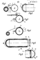
- the method in accordance with the invention can be utilized for the manufacture of tanks, containers and pipes, etc., of sandwich construction, but is described here as utilized for the manufacture of a cylindrical tank, for example a container tank.
- a cylindrical mandrel 1 capable of rotating about its longitudinal axis, open at one end and provided with, for example, a hemispherical end part 2 (see Fig. 2) at its other end.
- the mandrel 1 is best made of metal and manufactured accurately with regard to its dimensions and external finish. Its diameter may be increased (for the manufacture of tanks of larger diameters) by rolling a hard rubber mat onto the mandrel; in this way a limited number of mandrels will be required for tanks of different diameters.
- the first manufacturing operation which is illustrated in Fig. 1, consists of winding onto the mandrel 1 a single turn of an inner sheet 3 (for example, taken from a coil of this material having the same direction of curvature as the mandrel).
- the width of the sheet is the same as the length of the mandrel.
- a guide 4 with the same length as the width of the sheet and thus as the length of the mandrel.
- Ahead of the guide in the direction of winding is a short overlap (e.g. 50 mm), which at the end of the winding operation is provided over its entire area with adhesive via an adhesive spray 5. This may, if necessary, be resistant to lactic acid or citric acid, etc., depending on the proposed contents of the tank.
- the sheet 3 is cut by means of a cutting wheel 6 with an anvil.
- the cutting wheel runs parallel with the axis of the mandrel.
- the sheet is placed against the overlap and is taped, if necessary, in order to hold it in position.
- the guide 4 is then removed.
- the inner sheet 3 will now be of the correct length, but any adjustment can be made by the use of cutting wheels at either end, at right-angles to the axis of the mandrel 1.
- the next manufacturing operation which is illustrated in Fig. 2, consists of installing a separately manufactured end element 7 having the same sandwich construction as the cylindrical component (as described below).
- the inner sheet of the end element exhibits an overlap over the inner sheet of the cylindrical component, as may be appreciated from Fig. 2. Adhesive will have been applied to this overlap before the end element 7 is installed.
- the end element is taped into position, if necessary, to the cylindrical inner sheet so as to facilitate the following stages of manufacture.
- insulating layer 8 having a thickness which may vary from, say, 1 cm in the absence of any requirement for insulating capacity to 10 cm where full insulation is required.
- the insulating material used should preferably be a vinyl cell material (Divinycell R or similar), which is supplied in sheets in view of its rigidity.
- a sheet of this kind may ideally have the same width as the length of the mandrel 1 (the cylindrical part) and the same length as the circumference of the mandrel.
- the hard insulating material In order to facilitate its application the hard insulating material must be softened, which is achieved by moving the sheet from a stock of sheet material through a continuous microwave oven 9, in which heating up to 130-150 o C takes place with only small power requirement.
- the material is held in position by means of a guide 10 having the same length as the mandrel 1.
- the softened insulating material 8 is fed onto the rotating mandrel 1 on top of the inner sheet 3, which has been coated with an even layer of adhesive by an adhesive spray 11.
- the adhesive used in this case - and also in the bonding operations specified below - may be a polyurethane adhesive or an epoxy adhesive or similar.
- the insulation is formed precisely to the shape of the mandrel, but will cool rapidly since the mandrel 1 is cold.
- the guide 10 should be moved to each new sheet.
- the adhesive spray 11 may, for example, run on guides along the entire length of the mandrel 1, describing a to-and-fro motion as the mandrel rotates.
- a covering sheet 12 is applied in substantially the same way as the inner sheet 3 applied in the first stage, i.e. with an adhesive coated overlap ahead of a guide 13. If the sheet is not of the correct length, cutting may be performed, for example by means of a cutting wheel. Also at this stage, adhesive is applied in a uniform layer to the insulating layer 8 by means of an adhesive spray 14.
- the tank component manufactured to this stage on the mandrel has the appearance illustrated in Fig. 5.
- a plastic stocking 15 may be slipped over the entire mandrel, with a sealing ring being applied over the free end, and with an opening 17 being connected to the vacuum source until the adhesive has cured. The plastic stocking may then be removed.
- the mandrel must be removed before the manufacture of the tank can be completed. Removal can be facilitated, for instance, by forcing compressed air or water into the space between the mandrel and the tank (water to be used only if the mandrel has been enclosed in a rubber mat as mentioned above).
- Fig. 6 The final stage in the manufacture of the tank is illustrated in Fig. 6, this being the installation of a second end 18.
- This end is premanufactured from an inner sheet, an insulation sheet and a covering sheet in the form of an integral sandwich construction. It is clear from Fig. 6 that the covering sheet of this end exhibits an overlap over the covering sheet of the cylindrical body.
- a ring 19 which should be capable of being dismantled after installation of the end and of being removed through a hole in the tank, for example a manhole.
- a plastic stocking 20 is slipped over the end 18 after the adhesive has been applied to the contact surfaces and is secured in position by means of a sealing ring 21 or possibly by means of tape.
- An opening 22 is connected to the vacuum source.
- the mandrel used during manufacture may be of any desired cross- section, for example elliptical, square or rectangular, etc., and different types and sizes of tanks, cabinets and freight containers, etc., may be produced with advantage by this method.
- the entire manufacturing process may, by the choice of appropriate layout and peripheral equipment, take place at a single station, with the guides 4, 10 and 13 being a single guide and with the adhesive sprays 5, 11 and 14 being a single spray.
- the guide/guides may be replaced by inner vacuum cups or similar.
Landscapes
- Engineering & Computer Science (AREA)
- Mechanical Engineering (AREA)
- Lining Or Joining Of Plastics Or The Like (AREA)
- Making Paper Articles (AREA)
Applications Claiming Priority (2)
| Application Number | Priority Date | Filing Date | Title |
|---|---|---|---|
| SE8303650A SE446084B (sv) | 1983-06-27 | 1983-06-27 | Sett att framstella tankar, behallare och ror |
| SE8303650 | 1983-06-27 |
Publications (2)
| Publication Number | Publication Date |
|---|---|
| EP0130641A2 true EP0130641A2 (fr) | 1985-01-09 |
| EP0130641A3 EP0130641A3 (fr) | 1986-03-19 |
Family
ID=20351766
Family Applications (1)
| Application Number | Title | Priority Date | Filing Date |
|---|---|---|---|
| EP84200876A Withdrawn EP0130641A3 (fr) | 1983-06-27 | 1984-06-18 | Procédé de fabrication de réservoirs, tuyaux etc |
Country Status (3)
| Country | Link |
|---|---|
| US (1) | US4579617A (fr) |
| EP (1) | EP0130641A3 (fr) |
| SE (1) | SE446084B (fr) |
Cited By (3)
| Publication number | Priority date | Publication date | Assignee | Title |
|---|---|---|---|---|
| EP0464508A3 (en) * | 1990-06-23 | 1992-06-03 | Nichias Corporation | Method for shaping tetrafluoroethylene resin pipe |
| US7225048B2 (en) | 2000-11-28 | 2007-05-29 | Sumitomo Heavy Industries, Ltd. | Gap adjustment apparatus and gap adjustment method for adjusting gap between two objects |
| KR20210121198A (ko) * | 2019-02-12 | 2021-10-07 | 쌩-고벵 이조베르 | 절연 재료로부터 파이프 쉘을 제조하는 방법 및 장치 |
Families Citing this family (38)
| Publication number | Priority date | Publication date | Assignee | Title |
|---|---|---|---|---|
| US4744137A (en) * | 1985-09-12 | 1988-05-17 | Palazzo David T | Method of making double wall storage tank for liquids |
| US4927050A (en) * | 1985-09-12 | 1990-05-22 | Palazzo David T | Method of making double wall storage tank for liquids from a metal tank having a patterned surface |
| US5092951A (en) * | 1986-07-30 | 1992-03-03 | Softub, Inc. | Method of forming a tub apparatus |
| US4981543A (en) * | 1986-07-30 | 1991-01-01 | Softub, Inc. | Tub apparatus |
| US5527412A (en) * | 1986-07-30 | 1996-06-18 | Softub, Inc. | Spa apparatus |
| US5133818A (en) * | 1986-07-30 | 1992-07-28 | Softub, Inc. | Method of forming a tub apparatus |
| US4773952A (en) * | 1987-08-03 | 1988-09-27 | Biomagnetic Technologies, Inc. | Nonmetallic cylindrical cryogenic container |
| US4933040A (en) * | 1987-08-03 | 1990-06-12 | Biomagnetic Technologies, Inc. | Hollow article formed of composite material |
| US5047101A (en) * | 1987-09-22 | 1991-09-10 | Trussler Jared A | Method for fabricating an underground storage tank assembly |
| US4844287A (en) * | 1987-11-13 | 1989-07-04 | Long Delmar D | Leak containment system for underground storage tanks |
| US5077106A (en) * | 1988-04-19 | 1991-12-31 | The Boeing Company | Convolutely lined and wrapped composite tubes |
| US4900383A (en) * | 1988-04-19 | 1990-02-13 | The Boeing Company | Convolutely lined and wrapped composite tubes |
| US4923541A (en) * | 1988-10-22 | 1990-05-08 | George Burger | Method for making composite reinforced tubes |
| US5177340A (en) * | 1989-01-23 | 1993-01-05 | Cincinnati Milacron Inc. | Control of radiant heating system for thermoplastic composite tape |
| US4951844A (en) * | 1989-12-14 | 1990-08-28 | Sharp Bruce R | Double walled cylindrical-shaped storage tank with independent monitoring of tank areas |
| US5152859A (en) * | 1989-12-14 | 1992-10-06 | Sharp Bruce R | Method of making a double walled cylindrical-shaped storage tank with independent monitoring of tank areas |
| US5254197A (en) * | 1990-06-25 | 1993-10-19 | Lear Seating Corp. | Microwave bonding of foam to fabric using water as a susceptor |
| US5516384A (en) * | 1993-10-28 | 1996-05-14 | Ellman Consulting | System for manufacturing furniture and furniture parts of fibrous material cardboard |
| USD382945S (en) * | 1994-11-07 | 1997-08-26 | Softub, Inc. | Spa tub |
| US5745934A (en) * | 1996-06-10 | 1998-05-05 | Softub, Inc. | Spa apparatus with hanging structural liner |
| US5799345A (en) * | 1996-06-10 | 1998-09-01 | Softub, Inc. | Spa apparatus with multiple sections |
| US5794280A (en) * | 1997-01-08 | 1998-08-18 | Softub, Inc. | Spa apparatus with heat transferring hanging interior structural liner |
| US5980674A (en) * | 1997-02-11 | 1999-11-09 | Hillerich & Bradsby Co. | Method for manufacturing tubular constructions from fiber reinforced thermoplastic sheets |
| USD399306S (en) | 1997-06-18 | 1998-10-06 | Softub, Inc. | Spa tub |
| US6206793B1 (en) | 1997-12-23 | 2001-03-27 | Hillerich & Bradsby Co. | Composite hockey stick handle with resilient shroud |
| USD412544S (en) * | 1998-01-23 | 1999-08-03 | Hillerich & Bradsby Co., Inc. | Wooden hockey stick having an elastomeric sleeve about its handle |
| USD404449S (en) | 1998-01-23 | 1999-01-19 | Hillerich & Bradsby Co., Inc. | Hockey stick having an elastomeric sleeve about an aluminum shaft |
| GB2343410A (en) * | 1998-11-06 | 2000-05-10 | Corrosion Protection Systems L | A lid for a tank |
| US6120719A (en) * | 1998-12-18 | 2000-09-19 | Fsi International, Inc. | Method of joining plastic preforms to encapsulate an article |
| USD431273S (en) * | 1999-01-07 | 2000-09-26 | Hillerich & Bradsby Co. | Hockey stick having two wood veneers on opposed wide sides and composite cloth exposed on remaining sides |
| US6409873B1 (en) | 1999-01-20 | 2002-06-25 | Fsi International, Inc. | Process and apparatus for bonding a pair of ducts together in which a removable member is used to help support and maintain alignment between the ducts during bonding |
| CA2330083C (fr) * | 2000-01-07 | 2010-04-13 | Jas. D. Easton, Inc. | Baton de hockey |
| CA2357331C (fr) * | 2000-09-15 | 2010-07-20 | Jas D. Easton, Inc. | Baton de hockey |
| US7963868B2 (en) * | 2000-09-15 | 2011-06-21 | Easton Sports, Inc. | Hockey stick |
| US7232386B2 (en) * | 2003-05-15 | 2007-06-19 | Easton Sports, Inc. | Hockey stick |
| US7261794B2 (en) * | 2003-05-16 | 2007-08-28 | International Automotive Components Group, Llc | Method and apparatus for bonding a cover to a substrate using high frequency microwaves |
| WO2007059335A2 (fr) * | 2005-11-16 | 2007-05-24 | Easton Sports, Inc. | Crosse de hockey |
| US7914403B2 (en) * | 2008-08-06 | 2011-03-29 | Easton Sports, Inc. | Hockey stick |
Family Cites Families (13)
| Publication number | Priority date | Publication date | Assignee | Title |
|---|---|---|---|---|
| US1504805A (en) * | 1921-12-27 | 1924-08-12 | Borsodi Morris | Composite structure |
| US2301067A (en) * | 1940-05-29 | 1942-11-03 | Canister Company | Automatic laminating machine |
| FR1010126A (fr) * | 1948-07-30 | 1952-06-09 | Machine pour la fabrication de manchons cylindriques pour sacs et autres usages à partir d'une bande continue | |
| US3372075A (en) * | 1964-03-06 | 1968-03-05 | Amercoat Corp | Method of making an insulated storage tank |
| US3399095A (en) * | 1964-05-29 | 1968-08-27 | Owens Illinois Inc | Method and apparatus for producing containers of tubular foam laminates |
| US3655468A (en) * | 1964-08-06 | 1972-04-11 | Owens Corning Fiberglass Corp | Fluid-handling constructions, apparatus and methods of production |
| US3392865A (en) * | 1965-10-29 | 1968-07-16 | Nasa Usa | Filament-wound container |
| US3650868A (en) * | 1968-03-27 | 1972-03-21 | Furukawa Electric Co Ltd | Methods and apparatus for manufacturing pipe-shaped articles from foamed thermoplastic resin |
| US3854620A (en) * | 1971-05-03 | 1974-12-17 | Dana Corp | Container |
| US4118814A (en) * | 1975-11-17 | 1978-10-10 | Gerald Herbert Holtom | Manufacture of boat hulls and other hollow articles |
| US4126659A (en) * | 1976-07-09 | 1978-11-21 | Lockheed Aircraft Corporation | Method of making a hollow article |
| DE2706899A1 (de) * | 1977-02-17 | 1978-08-31 | Muanyagipari Kutato Intezet | Verfahren und vorrichtung zur herstellung von aus verstaerktem kunststoff angefertigten gewickelten formkoerpern mit sandwich-struktur |
| US4250797A (en) * | 1978-12-28 | 1981-02-17 | Consolidated Foods Corp. | Apparatus for making corrugated packages |
-
1983
- 1983-06-27 SE SE8303650A patent/SE446084B/sv unknown
-
1984
- 1984-06-18 EP EP84200876A patent/EP0130641A3/fr not_active Withdrawn
- 1984-06-19 US US06/622,231 patent/US4579617A/en not_active Expired - Fee Related
Cited By (3)
| Publication number | Priority date | Publication date | Assignee | Title |
|---|---|---|---|---|
| EP0464508A3 (en) * | 1990-06-23 | 1992-06-03 | Nichias Corporation | Method for shaping tetrafluoroethylene resin pipe |
| US7225048B2 (en) | 2000-11-28 | 2007-05-29 | Sumitomo Heavy Industries, Ltd. | Gap adjustment apparatus and gap adjustment method for adjusting gap between two objects |
| KR20210121198A (ko) * | 2019-02-12 | 2021-10-07 | 쌩-고벵 이조베르 | 절연 재료로부터 파이프 쉘을 제조하는 방법 및 장치 |
Also Published As
| Publication number | Publication date |
|---|---|
| SE8303650L (sv) | 1984-12-28 |
| SE446084B (sv) | 1986-08-11 |
| EP0130641A3 (fr) | 1986-03-19 |
| US4579617A (en) | 1986-04-01 |
| SE8303650D0 (sv) | 1983-06-27 |
Similar Documents
| Publication | Publication Date | Title |
|---|---|---|
| EP0130641A2 (fr) | Procédé de fabrication de réservoirs, tuyaux etc | |
| US3620869A (en) | Method of making tubes | |
| US3524779A (en) | Method of making wound tubular products | |
| JP2554842B2 (ja) | 円筒形コンテナ本体に外巻きへりを形成する方法及び装置 | |
| US3819085A (en) | Lap side seam of metal, tubular body and method for making same | |
| US2814313A (en) | Manufacture of pipe | |
| EP0111356A1 (fr) | Récipient cylindrique | |
| US2354556A (en) | Method of forming laminated tubular bodies | |
| US3439590A (en) | Method for heat sealing | |
| WO1989006631A1 (fr) | Reservoirs de stockage avec nervures de support fabriquees | |
| EP1094903A1 (fr) | Rouleau a peinture a noyau integre et protection, et procede et dispositif de fabrication associes | |
| US2998339A (en) | Production of tubes and structural shapes from metal foils | |
| US5131688A (en) | Pipe insulator and method for making same | |
| US3816206A (en) | Method for protecting raw metal edge of inside lap of adhesively bonded lap side seam tubular body | |
| US3877136A (en) | Method of thermally insulating pipe | |
| DE3176860D1 (en) | Method for manufacturing a liquid-tight container | |
| US2584564A (en) | Magnetic core member | |
| US2803730A (en) | Method of forming lined tubing | |
| US11040479B2 (en) | Structure and method for manufacturing structure | |
| GB2109712B (en) | Manufacturing the peripheral wall of a tank for an oil-immersed electric apparatus | |
| US3495506A (en) | Method for the production of a multi-ply tubular article | |
| EP0184759B1 (fr) | Appareil pour la production discontinue de structures tubulaires ou de structures que l'on peut obtenir à partir de structures tubulaires | |
| US3399094A (en) | Method for forming tubular reinforced plastic members | |
| CA1157362A (fr) | Methode de fabrication de contenants d'emballage, et produit ainsi obtenu | |
| US3783908A (en) | Helically wound tubes |
Legal Events
| Date | Code | Title | Description |
|---|---|---|---|
| PUAI | Public reference made under article 153(3) epc to a published international application that has entered the european phase |
Free format text: ORIGINAL CODE: 0009012 |
|
| AK | Designated contracting states |
Designated state(s): DE FR GB IT SE |
|
| PUAL | Search report despatched |
Free format text: ORIGINAL CODE: 0009013 |
|
| AK | Designated contracting states |
Kind code of ref document: A3 Designated state(s): DE FR GB IT SE |
|
| STAA | Information on the status of an ep patent application or granted ep patent |
Free format text: STATUS: THE APPLICATION IS DEEMED TO BE WITHDRAWN |
|
| 18D | Application deemed to be withdrawn |
Effective date: 19861120 |
|
| RIN1 | Information on inventor provided before grant (corrected) |
Inventor name: OEBERG, LARS-GUNNAR Inventor name: BJURLING, ANDERS Inventor name: CARLSSON, BO W. |