EP0130657A1 - Plombe enthaltende Verschlussanordnung - Google Patents
Plombe enthaltende Verschlussanordnung Download PDFInfo
- Publication number
- EP0130657A1 EP0130657A1 EP84200979A EP84200979A EP0130657A1 EP 0130657 A1 EP0130657 A1 EP 0130657A1 EP 84200979 A EP84200979 A EP 84200979A EP 84200979 A EP84200979 A EP 84200979A EP 0130657 A1 EP0130657 A1 EP 0130657A1
- Authority
- EP
- European Patent Office
- Prior art keywords
- plumb
- disc
- projections
- sealing
- recesses
- Prior art date
- Legal status (The legal status is an assumption and is not a legal conclusion. Google has not performed a legal analysis and makes no representation as to the accuracy of the status listed.)
- Withdrawn
Links
- 238000007789 sealing Methods 0.000 title claims abstract description 33
- 239000000463 material Substances 0.000 claims abstract description 6
- 210000000080 chela (arthropods) Anatomy 0.000 description 2
- 230000007547 defect Effects 0.000 description 1
- XLYOFNOQVPJJNP-UHFFFAOYSA-N water Substances O XLYOFNOQVPJJNP-UHFFFAOYSA-N 0.000 description 1
Images
Classifications
-
- G—PHYSICS
- G09—EDUCATION; CRYPTOGRAPHY; DISPLAY; ADVERTISING; SEALS
- G09F—DISPLAYING; ADVERTISING; SIGNS; LABELS OR NAME-PLATES; SEALS
- G09F3/00—Labels, tag tickets, or similar identification or indication means; Seals; Postage or like stamps
- G09F3/02—Forms or constructions
- G09F3/03—Forms or constructions of security seals
- G09F3/0305—Forms or constructions of security seals characterised by the type of seal used
- G09F3/0364—Forms or constructions of security seals characterised by the type of seal used having rotary sealing means
-
- G—PHYSICS
- G09—EDUCATION; CRYPTOGRAPHY; DISPLAY; ADVERTISING; SEALS
- G09F—DISPLAYING; ADVERTISING; SIGNS; LABELS OR NAME-PLATES; SEALS
- G09F3/00—Labels, tag tickets, or similar identification or indication means; Seals; Postage or like stamps
- G09F3/02—Forms or constructions
- G09F3/03—Forms or constructions of security seals
- G09F3/0305—Forms or constructions of security seals characterised by the type of seal used
- G09F3/0347—Forms or constructions of security seals characterised by the type of seal used having padlock-type sealing means
- G09F3/0352—Forms or constructions of security seals characterised by the type of seal used having padlock-type sealing means using cable lock
Definitions
- the invention relates to a sealing device comprising a plumb having a sealing chord, the plumb being received in the annular aperture of an annular disc, openings being provided in the disc and in the plumb for the passage of the legs of the sealing chord.
- a sealing device is known from the DE-C 638.743.
- Such devices serve for sealing certain apparatus and spaces, e.g. gas flow meters, Watt meters and water meters.
- Government Standards Offices for many situations use the plumb for sealing computing apparatus suitable for commercial purposes.
- customs offices use such sealing devices for sealing several spaces or stores.
- the known sealing devices are structurally designed such that an unseparable connection is established between the loop shaped sealing element, e.g. a sealing chord carrying a plumb and the object to be sealed,by means of a pair of sealing pinchers.
- the invention aims at providing a sealing device whereby the infringement of the plumb is immediately observed by the competent authorities.
- the disc is manufactured of a material which irreversably changes in shape or colour if thereon forces are imparted for breaking the seal.
- forces may e.g. be imparted by means of a pair of pincers.
- This phenomenon is also known as stress-whiting.
- Polysterene which may be coloured or not coloured, is suitable therefor, but also other material may be used.
- the invention furthermore aims at facilitating the provisior of said sealing device.
- the plumb has to be placed in the disc such that the through openings therein become situated opposite to those in the disc in order to permit threading of the sealing loop chord.
- Said projections are provided such that the openings for threading the sealing loop are aligned thereby.
- the falling through of the plumb may also be prevented when the projections have an outer surface forming a sharp angle with the plumb axis.
- the corresponding recesses in the disc may extend through half the disc thickness, starting from one disc end surface, while identical recesses are provided in the other half of the disc thickness and starting from the other disc end surface.
- the projections are in the shape of half spheres, the sphere center thereof being substantially in the circumferential surface of the plumb, whereas the recesses are half cylindrical and open into at least one of the disc end surfaces.
- the spherical shape provides an aiming possibility whereby if the diametral directions of the projections and the recesses initially not completely coincide when the plumb is placed, the correct position is obtained through the aiming action.
- the falling through of the plumb is prevented if therewith the recesses in the disc terminate at a position spaced from one of the disc end surfaces.
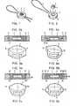
- Said sealing device has been assembled from a sealing chord 1, a sealing plumb 2 and a sealing disc 3.
- the chord 1 is threaded through eyes (not shown) provided on the apparatus to be sealed, such that said eyes are kept together by the sealing chord so that the apparatus may not be opened.
- the disc 3 thereto is provided with an annular aperture 4 of such form and dimensions that the plumb 2 therein fits freely or with an interference fit.
- the disc 4 has one or more apertures 5, 6 extending parallel to a radius thereof and provided as through bores of the disc, each time a bore 5 at one side being aligned with a bore 6 at the diametrally other side of the disc.
- the plumb 2 has one or more recesses 7,in the embodiment shown a single elongate recess extending transversely to the axis of the cylindrical plumb.
- each end of the tluead is threaded through an aperture 5, through the recess or aperture 7 in the plumb after this has been placed in the annular opening of the disc, and through the bore 6 of the disc aligned therewith. If thereafter a clamping force is imparted to both end surfaces of the plumb by means of a pair of pincers, the plumb is clamped to the thread and in the disc 3 in that the plumb is pressed in engagement with the wall of the annular opening in the disc. It is preferable to form a chamber or undercut edge in said inner wall of the opening such as is also provided in known sealing devices. This has not been shown in figures 1 and 2.
- the disc and the plumb may also have a different shape from the circular cylindrical shape as shown.
- the plumb is provided with in this case two diametral projections and the disc with corresponding recesses or vice versa, the disc with the projections and the plumb with the corresponding recesses.
- the plumb has the projections.
- Fig. 3a shows a cylindrical plumb 2, having a through going recess 7.
- two diametrically opposite projections 8 are provided on the plumb, said projections being substantially half cylindrical in shape and are integral with the plumb 2 proper.
- the projections 8 extend through the complete thickness of the plumb.
- corresponding recesses 9 are provided in the disc 3, which is shown in diametral section in figure 3b.
- Figure 4a shows the same projections, here indicated by the reference number 10, on a plumb 2, however, said projections extend through half the height or thickness of the plumb.
- the corresponding recesses in the disc 3 are indicated with the reference number 11, whereas the annular opening in the disc has a cir- cumferencial undercut edge 12, while moreover a chamber 13 has been formed therein.
- Figure 5a shows a plumb having two diametral projections 14 which are substantially half cones, the apex of which is contained in one end surface and the base in the other end surface of the plumb.
- the corresponding disc according to figure 5b here has corresponding half conical recesses 15' in the upper part, extending through half the height or thickness and extending according to the same apex angle as the projections 14, the plumb 2 with its projection being supported therein only through half the height, the remainder of the projections extending freely in a chamber of the disc 3.
- corresponding recesses 15" are provided in the lower part of the disc, having the same apex angle, so that the plumb may also be placed in the disc 3 when in reverted position.
- the disc has been shown as having a chamber 16 for receiving the outwardly pressed plumb material.
- Fig. 6 finally shows in figure 6a a plumb 2 having diametral projections 17, which are substantially shaped as half spheres which are integrally connected with the sectional surfaces adjacent to and with the plumb.
- the corresponding disc 3 has through going half cylindrical recesses 18, having a slightly larger radius than the sphere radius.
- the edges of the central disc opening may be rounded in the disc end surfaces at 19 in order to further the aiming action of the projections 17.
- the disc 3 is shown here as having a chamber 20, which is V-shaped in section and adapted for receiving plumb material when the plumb is pressed into the disc.
- the projections 17 not extending through the complete height of the plumb, the disc opening having at the one end surface an undercut edge (not shown) on which the projections (17) become supported when the plumb is placed into the disc. In that case the plumb cannot drop through the disc or does not require to be supported in order to prevent dropping through.
- the disc 3 may have any shape of its outer circumference, which facilitates handling thereof by a machine for providing the plumbs in the disc, e.g. circular, but having two straight portions, or provided with notches or projections.
- the disc may have inward projections, relative to a circular shape, when the opening in the disc is triangular or has any other shape, in which case the plumb should have a circumferential shape corresponding therewith.
Landscapes
- Engineering & Computer Science (AREA)
- Computer Security & Cryptography (AREA)
- Physics & Mathematics (AREA)
- General Physics & Mathematics (AREA)
- Theoretical Computer Science (AREA)
- Closures For Containers (AREA)
Applications Claiming Priority (4)
| Application Number | Priority Date | Filing Date | Title |
|---|---|---|---|
| NL8302389 | 1983-07-05 | ||
| NL8302389A NL8302389A (nl) | 1983-07-05 | 1983-07-05 | Verzegelinrichting, voorzien van een zegelloodje. |
| NL8400802 | 1984-03-13 | ||
| NL8400802A NL8400802A (nl) | 1984-03-13 | 1984-03-13 | Verzegelinrichting, voorzien van een zegelloodje. |
Publications (1)
| Publication Number | Publication Date |
|---|---|
| EP0130657A1 true EP0130657A1 (de) | 1985-01-09 |
Family
ID=26645874
Family Applications (1)
| Application Number | Title | Priority Date | Filing Date |
|---|---|---|---|
| EP84200979A Withdrawn EP0130657A1 (de) | 1983-07-05 | 1984-07-04 | Plombe enthaltende Verschlussanordnung |
Country Status (1)
| Country | Link |
|---|---|
| EP (1) | EP0130657A1 (de) |
Cited By (2)
| Publication number | Priority date | Publication date | Assignee | Title |
|---|---|---|---|---|
| GB2323584A (en) * | 1997-03-26 | 1998-09-30 | John Artingstoll | Tagging System |
| FR3053714A1 (fr) * | 2016-07-08 | 2018-01-12 | K Plast | Dispositif de scellage comprenant un bouton de verrouillage a actionner pour passer dans un etat scelle du dispositif de scellage |
Citations (5)
| Publication number | Priority date | Publication date | Assignee | Title |
|---|---|---|---|---|
| FR559437A (fr) * | 1922-12-05 | 1923-09-15 | Système de plomb de sûreté | |
| FR602630A (fr) * | 1924-08-27 | 1926-03-23 | Scellé perfectionné en plomb ou matières plastiques analogues | |
| DE638743C (de) * | 1936-11-21 | Ernst Frank | Mit einem Etikett verbundene Schnurplombe | |
| FR808112A (fr) * | 1936-07-15 | 1937-01-29 | Plombs de scellement pour les endroits des noeuds des cordons de ligatures ou analogues | |
| US2884123A (en) * | 1956-09-24 | 1959-04-28 | American Home Prod | Tamper-proof injection cartridge housing |
-
1984
- 1984-07-04 EP EP84200979A patent/EP0130657A1/de not_active Withdrawn
Patent Citations (5)
| Publication number | Priority date | Publication date | Assignee | Title |
|---|---|---|---|---|
| DE638743C (de) * | 1936-11-21 | Ernst Frank | Mit einem Etikett verbundene Schnurplombe | |
| FR559437A (fr) * | 1922-12-05 | 1923-09-15 | Système de plomb de sûreté | |
| FR602630A (fr) * | 1924-08-27 | 1926-03-23 | Scellé perfectionné en plomb ou matières plastiques analogues | |
| FR808112A (fr) * | 1936-07-15 | 1937-01-29 | Plombs de scellement pour les endroits des noeuds des cordons de ligatures ou analogues | |
| US2884123A (en) * | 1956-09-24 | 1959-04-28 | American Home Prod | Tamper-proof injection cartridge housing |
Cited By (2)
| Publication number | Priority date | Publication date | Assignee | Title |
|---|---|---|---|---|
| GB2323584A (en) * | 1997-03-26 | 1998-09-30 | John Artingstoll | Tagging System |
| FR3053714A1 (fr) * | 2016-07-08 | 2018-01-12 | K Plast | Dispositif de scellage comprenant un bouton de verrouillage a actionner pour passer dans un etat scelle du dispositif de scellage |
Similar Documents
| Publication | Publication Date | Title |
|---|---|---|
| FI78991C (fi) | System foer placerande av en provflaska. | |
| CA1093501A (en) | Child-resistant pill dispenser | |
| US4641759A (en) | Safety bottle closure having a time indicator | |
| US4634012A (en) | Safety bottle closure having a time indicator | |
| US4387821A (en) | Stopping device for bottle | |
| US5611368A (en) | Valve having magnetic force transmission apparatus | |
| US6651305B2 (en) | Method and apparatus for automatically handling a sample cup cap | |
| US3023939A (en) | Dispensing closures | |
| JPS6274419A (ja) | 改良型濾過組立体 | |
| US20190127129A1 (en) | Cap For A Pouch | |
| JP2009073570A (ja) | 遠心分離機用コンテナのキャップおよびキャップ組立体 | |
| US3986635A (en) | Closure locking and orienting device | |
| US2783515A (en) | Dual fastener | |
| EP0130657A1 (de) | Plombe enthaltende Verschlussanordnung | |
| US4303519A (en) | Quick disconnect bag filter | |
| US4507718A (en) | LED Holder | |
| ES553366A0 (es) | Una valvula de salida para un recipiente que contiene una masa en estado de fusion | |
| US4621658A (en) | Non-removable spring holder for a pressure operated valve | |
| WO1997031833A1 (en) | A combination comprising a container part and a closure part | |
| US4027342A (en) | Goggle ventilator | |
| WO1998042587A3 (en) | Non-refilling devices for containers | |
| US4747217A (en) | Pendulum style level | |
| US4117666A (en) | Quick reset timer | |
| US4331178A (en) | Curb box for plastic valve | |
| US3565274A (en) | Closure and sealing assembly for bottles |
Legal Events
| Date | Code | Title | Description |
|---|---|---|---|
| PUAI | Public reference made under article 153(3) epc to a published international application that has entered the european phase |
Free format text: ORIGINAL CODE: 0009012 |
|
| AK | Designated contracting states |
Designated state(s): AT BE CH DE FR GB IT LI LU NL SE |
|
| STAA | Information on the status of an ep patent application or granted ep patent |
Free format text: STATUS: THE APPLICATION IS DEEMED TO BE WITHDRAWN |
|
| 18D | Application deemed to be withdrawn |
Effective date: 19850910 |