EP0130663B1 - Pièce d'attache captive pour bois d'arrimage - Google Patents
Pièce d'attache captive pour bois d'arrimage Download PDFInfo
- Publication number
- EP0130663B1 EP0130663B1 EP84302240A EP84302240A EP0130663B1 EP 0130663 B1 EP0130663 B1 EP 0130663B1 EP 84302240 A EP84302240 A EP 84302240A EP 84302240 A EP84302240 A EP 84302240A EP 0130663 B1 EP0130663 B1 EP 0130663B1
- Authority
- EP
- European Patent Office
- Prior art keywords
- head
- track
- sides
- neck
- openings
- Prior art date
- Legal status (The legal status is an assumption and is not a legal conclusion. Google has not performed a legal analysis and makes no representation as to the accuracy of the status listed.)
- Expired
Links
- 230000000717 retained effect Effects 0.000 claims description 4
- 239000000463 material Substances 0.000 claims description 2
- 210000003739 neck Anatomy 0.000 description 17
- 238000010276 construction Methods 0.000 description 5
- 238000009434 installation Methods 0.000 description 2
- 239000002184 metal Substances 0.000 description 2
- 229910000831 Steel Inorganic materials 0.000 description 1
- 230000000295 complement effect Effects 0.000 description 1
- 238000006073 displacement reaction Methods 0.000 description 1
- 238000009408 flooring Methods 0.000 description 1
- 230000014759 maintenance of location Effects 0.000 description 1
- 238000005096 rolling process Methods 0.000 description 1
- 239000010959 steel Substances 0.000 description 1
- 239000002023 wood Substances 0.000 description 1
Images
Classifications
-
- B—PERFORMING OPERATIONS; TRANSPORTING
- B61—RAILWAYS
- B61D—BODY DETAILS OR KINDS OF RAILWAY VEHICLES
- B61D45/00—Means or devices for securing or supporting the cargo, including protection against shocks
- B61D45/008—Shock absorbing devices
-
- B—PERFORMING OPERATIONS; TRANSPORTING
- B60—VEHICLES IN GENERAL
- B60P—VEHICLES ADAPTED FOR LOAD TRANSPORTATION OR TO TRANSPORT, TO CARRY, OR TO COMPRISE SPECIAL LOADS OR OBJECTS
- B60P7/00—Securing or covering of load on vehicles
- B60P7/06—Securing of load
- B60P7/135—Securing or supporting by load bracing means
- B60P7/15—Securing or supporting by load bracing means the load bracing means comprising a movable bar
-
- Y—GENERAL TAGGING OF NEW TECHNOLOGICAL DEVELOPMENTS; GENERAL TAGGING OF CROSS-SECTIONAL TECHNOLOGIES SPANNING OVER SEVERAL SECTIONS OF THE IPC; TECHNICAL SUBJECTS COVERED BY FORMER USPC CROSS-REFERENCE ART COLLECTIONS [XRACs] AND DIGESTS
- Y10—TECHNICAL SUBJECTS COVERED BY FORMER USPC
- Y10T—TECHNICAL SUBJECTS COVERED BY FORMER US CLASSIFICATION
- Y10T403/00—Joints and connections
- Y10T403/59—Manually releaseable latch type
- Y10T403/599—Spring biased manipulator
-
- Y—GENERAL TAGGING OF NEW TECHNOLOGICAL DEVELOPMENTS; GENERAL TAGGING OF CROSS-SECTIONAL TECHNOLOGIES SPANNING OVER SEVERAL SECTIONS OF THE IPC; TECHNICAL SUBJECTS COVERED BY FORMER USPC CROSS-REFERENCE ART COLLECTIONS [XRACs] AND DIGESTS
- Y10—TECHNICAL SUBJECTS COVERED BY FORMER USPC
- Y10T—TECHNICAL SUBJECTS COVERED BY FORMER US CLASSIFICATION
- Y10T403/00—Joints and connections
- Y10T403/60—Biased catch or latch
- Y10T403/602—Biased catch or latch by separate spring
Definitions
- Dunnage bars are commonly employed in rail cars, semitrailers, ship holds, freight containers and the like to prevent the shifting of freight and to serve as supports for elevated floors.
- dunnage bars commonly consist of an elongated bar element having end fittings cooperating with elongated fixed tracks attached to the walls of the freight transporting vehicle.
- fittings are used to connect the bar to the tracks and a variety of locks are employed for releasably connecting the fittings to the tracks permitting adjustment of the bars relative to the track and preventing accidental release therefrom.
- dunnage bar fittings are fully releasable from the associated track permitting the bar to be removed from complete association with the track, and as the requirements and usage of dunnage bars varies with each freight load the dunnage bars are often removed from the vehicle or stored in such a location as to be damaged, or inadvertently or purposely discarded.
- a dunnage bar, and its associated fittings is a relatively expensive apparatus the loss or damage of the bar imposes high costs upon the vehicle owner or shipper responsible for the dunnage equipment, and there has been a need for dunnage bars capable of versatile adjustment within its tracks but which cannot be lost or discarded.
- a further object of the invention is to provide a captive dunnage bar system utilizing a bar having end fittings associated with a fixed elongated track wherein the end fittings are locked within the track, but are selectively adjustable therein between predetermined locations.
- GB-A-815009 discloses a securing system in accordance with the prior art portion of claim 1.
- This prior construction has a retaining means in which a head is rotatable in a track between a retaining position in which it engages apertures in opposite sides of the track and a release position.
- this prior system contains neither of the features which are essential to the present invention in that the head, when in its release position, can simply be removed through the slot in the track and in that no means are provided for locking the head in position.
- the present invention is characterised in that the system is a captive dunnage bar system at each end of which an individual mounting neck extends from the bar to engage a respective vertical fixed track, the head is pivotally mounted on said neck and has a width greater than the track slot width whereby said head is retained within the track, the first and second portions of the head are comprised by projections from the head sides, locking means are provided upon said neck releasably to lock said head in said first rotative orientation, said locking means including a notch defined in said head, a lever pivotally mounted upon said neck having a first position engaging said notch locking said head in said first rotative orientation and a second position releasing said lever from said notch, and releasable spring biased detent means to maintain said lever in said first position.
- the dunnage bar is captive to the track and although being readily shiftable therealong when the head is in its release position even in its release position the head is held captive in the track. Furthermore, a particularly simple and effective locking system is provided which is relatively stress free and which readily enables the head to be held in this position in which it locks the dunnage bar at a particular location in the track.
- the head length is greater than the spacing between said track sides whereby said head sides engage said track sides upon the head being rotated to the second rotative orientation limiting rotation of the head.
- the projections can engage the top edges of the apertures in the track to cam the head automatically to rotate to its position for longitudihal movement along the track responsive to lifting movement of the dunnage bar.
- one of the head projections includes a notch to receive therein the track material at the associated opening at the first rotative orientation of the head. This provides positive retention of the head in its dunnage bar supporting position responsive to weight applied upon the dunnage bar without putting any strain on the locking system.
- the locking system simply operates to retain the head engagement with the track apertures should an attempt be made to lift the dunnage bar when the lock is engaged.
- track configurations may be used in the practice of the invention, and various configurations are illustrated wherein the track may be incorporated into the walls of the cargo space, and may serve as structural members.
- the track elements may include means for cooperating with the cargo space walls and such "built-in" track forms eliminate the likelihood of track damage while providing an attractive appearance within the cargo space.
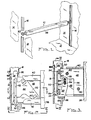
- a typical dunnage installation utilizing the invention is disclosed in a general manner.
- the cargo space in which the dunnage bar 10 is to be used includes a floor represented at 12, and spaced walls are represented at 14. This space may exist within a rail car, a truck trailer, van, ship hold, freight container, or the like.
- Identical parallel tracks 16 are mounted upon opposite walls of the freight holding space, and the tracks may be surface mounted, as illustrated, orflush mounted, as later described.
- the bar 10 extends across the freight holding space between the walls, and serves to confine the freight against shifting in a direction transverse to the bar length, or the dunnage bar may be used to support elevated flooring or shelving, not shown, to define elevated storage space above floor 12.
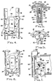
- the track illustrated in Figs. 1-8 has a configuration best appreciated from Figs. 4 and 5.
- the track is preferably formed of rolled steel having a flat central region 18 in which holes 20 are defined for receiving mounting screws 22 for attaching the track to the supporting wall 14.
- the track includes lateral side portions 24 which are in opposed parallel relationship to each other, the maximum internal dimension being defined between opposed concave surfaces 26, Fig. 5.
- the sides 24 extend toward each other at 28 terminating in parallel edges 30 defining a slot 32 of lesser width then the dimension between the surfaces 26 of the sides.
- Openings 34 and 36 are defined in the sides 24 of the track, these openings being of an elongated nature, Fig. 4, and the openings defined in the sides are axially offset with respect to each other as will be appreciated from Fig. 4.
- a track constructed as aforedescribed is economically manufactured, rugged, of a high strength, and resistant to damage.
- the dunnage bar 10 in its simplest form, consists of an elongated central member 38 which may be formed of wood or metal, or a combination thereof. As the bar disclosed is of the "captive" type, it is not necessary that the bar be longitudinally adjustable of have telescoping components as is often the case with conventional dunnage and bracing bar systems.
- Each end of the bar 10 includes a plurality of metal components bolted to the portion 38 and extending from the ends thereof. These components include an upper cap 40, a lower cap 42, Fig. 2, a U-shaped neck 44, a pair of spaced plates 46 and a central plate 48.
- the neck includes parallel leg portions 50 and a base portion 52 having flanges 54 extending beyond the edges of the legs, Fig. 3. The internal.
- the plates 46 terminate short of the base 52, as does the central plate 48, and the central plate is recessed at its lower edge, Fig. 7, providing a cavity 56 having a concave notch 58 formed therein for a purpose later described.
- the legs 50 are of the configuration apparent in Fig. 2 and are fastened to the plates 46 and central plate 48 by rivets or bolts 60 wherein the neck is integrally affixed to the bar portion 38.
- a fitting head 62 of a planar plate configuration is mounted upon the neck 44.
- the head 62 is of a generally quadrangular configuration, Figs. 4 and 8, having a width defined by sides 64 and a length defined by parallel end edges 66.
- a projection 68 is defined upon the head forming abutment surfaces 70 and 72, and a hook projection 74 is defined upon the opposite sides of the fitting head defining a notch 76.
- the head 62 is formed with an opening 78 permitting the head to be mounted upon the neck legs 50 and rotatable thereto. The configuration of the head opening 78 will be appreciated from Fig. 4 wherein a limited rotation of about 20° is possible.
- the dimension of the head opening 78 with respect to the length of the base 52 is less than the length of the neck base as defined by flanges 54, and in this manner when the neck is assembled to the bar plates 46 the head 62 is retained upon the neck legs, and is rotatable thereto through a limited degree of rotation as will be apparent from the following description.
- the head 62 is provided with a notch 80 which co-operates with a locking lever 82, Fig. 7, when the head is in the operative position.
- the locking lever 82 is pivotally mounted upon a pivot pin 84 extending through plates 46, and the lever is provided with an elongated slot 86 which includes spring 88 which biases the lever upwardly, Fig. 3.
- the lever is provided with a convex end surface 90 complementary in radius to the central plate notch 58 and the locking lever includes a detent portion 92, a locking plate 94 at right angles to the main body portion of the lever, and a stop tang 96.
- the locking lever 82 can be moved downwardly, Figs. 3 and 7, against the tension of the spring 88, and may be pivoted between the operative position of Fig. 3, and the inoperative position of Fig. 7 once the lever has been moved downwardly sufficiently to clear the end 90 from the notch 58.
- each end of the bracing bar portion 38 is provided with an end fitting identical to that described above.
- the width of the fitting head 62 as defined by sides 64 is greater than the width of the slot 32 as defined by track edges 30, but the width of the head is less than the maximum width of the track as defined by the spacing between the surfaces 26. Accordingly, when initially assembled the bar necks 44 extend into the tracks through the slots 32 and the heads 62 will be located within the confines of the track. As the plane of the fitting heads 62 is perpendicular to the length of the bar portion 38 the bar is "captive" with respect to its tracks and cannot be removed therefrom, although the bar.
- Fig. 8 may be adjusted in the direction of the track lengths when the locking lever detent 92 is not received within the head notch 80, such as in Fig. 8.
- the head 62 will be rotated relative to the neck 44 as illustrated in Fig. 8 and the head is readily slidable within the track and the neck within the slot 32.
- the operator will push the bar in the direction which forces the head surface 64' against its adjacent track surface 26, Fig. 8, which will maintain the head in an alignment which prevents the projections 68 and 74 from entering the track openings 36 and 34, respectively.
- the head cam surfaces 98 and 100 may engage the edges of the adjacent openings, but such engagement will tend to pivot the head in the counterclockwise direction further preventing the projections from entering the track openings.
- inadvertent engagement of the head projections with the openings can again be prevented by maintaining engagement of the head edge 64' with the adjacent track surface 26, and the cam surface 102 defined upon the head aids in preventing hook projection 76 from entering an opening 34 if the head is not moved too far to the left, Fig. 8. Accordingly, the bar 10 may be readily adjusted within both tracks 16 simultaneously in either direction.
- the operator When it is desired to lock the dunnage bar in its operative position the operator will pull the bracing bar in a direction to the left, Figs. 4 and 8, and simultaneously lower the bar. Such action permits the hook projection 74 to enter an opening 34 engaging the opening lower edge causing the head to pivot in a clockwise direction, Fig. 4, thrusting projection 68 into opening 36, and further inserting the hook projection into the opening 34 so that the notch 76 will fully engage the track opening edge as apparent in Fig. 4. When fully associated with the track openings the fitting head 62 will be in the position shown in Fig. 4 wherein abutment surfaces 70 and 72 are in engagement with the track and the notch 80 is in alignment with the locking lever 82.
- the locking lever 82 is then pivoted to the locked position of Fig. 3 permitting detent portion 92 to enter the notch 80 which prevents rotation of the head 62 upon the neck 44, and locking plate 94 enters slot 32 to prevent rotation of the bar 38 relative to the track.
- the dunnage bar 10 is locked in its operative position and capable of transmitting high downward forces on the tracks 16 through the heads 62.
- the bar 10 When not in use, the bar 10 may be easily lifted within its tracks 16 to its uppermost position wherein the bar will be overhead with respect to the floor 12 permitting traffic therebelow, and lift trucks and other load handling equipment may readily pass below the bar, and the bar may easily be maintained in such an elevated non-use position. However, the bar cannot be removed from association with its tracks.
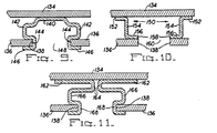
- Figs. 9-11 illustrate variations in track structure with which the fitting of the invention may be employed.
- the track it is necessary that the track have parallel opposed side portions in which the fitting head projection receiving openings are defined, and also, the track must define an elongated slot parallel to the track length which is of a lesser width than the track sides in which the openings are defined insuring that the fitting head will be held captive within the track.
- reference 134 represents the primary support wall of the cargo space, and may constitute the exterior wall of a trailer or freight container,
- the freight space is defined by inner panels 136 defining an inner wall, the adjacent panels being spaced from each other and being defined by parallel edges 138.
- the track consists of a single element as with the previously described track embodiment, and includes a base portion 140 in which holes are defined whereby fasteners are used to attach the track to the wall 134.
- the track is shaped, usually by rolling, to define parallel spaced sides 142 in which openings are formed relatively axially spaced in the manner apparent from Fig. 4.
- the edge portions of the track are then formed in a U-configuration to define notches 144 which closely receive the edges of the inner panels 136. Openings are preferably defined in the leg portions 146 for receiving fasteners for attaching the panels to the track.
- the slot 148 is of lesser width than the dimensions separating the sides 142.
- the track consists of a pair of "Z" members 150 each including a flange 152 having openings defined therein for attachment to the wall 134 by fasteners.
- the intermediate side portions 154 are in spaced parallel relationship having openings defined therein for receiving the fitting head projections, the openings being spaced as aforedescribed.
- the inwardly extending flanges 156 are provided with openings whereby fasteners attach the inner panels 136 to the flanges 156, and the flange ends 158 will define the slot 160 through which the fitting head extends.
- the track is not visible as only the slots defined by the panel ends 138 are exposed.
- a pair of identical elements each include mounting flanges 162 having holes permitting attachment to the wall 134.
- Portions 164 may be varied in dimension wherein this type of track can be used to accommodate situations where considerable thickness occurs between the wall 134 and the panels 136.
- the sides 166 define the fitting head projection receiving openings, and the U-shaped portions 168 define notches receiving the ends of the inner panels.
- the tracks may serve as the structural components for the freight confining space, such as columns within a trailer van for supporting the roof, or the like.
Landscapes
- Engineering & Computer Science (AREA)
- Transportation (AREA)
- Mechanical Engineering (AREA)
- Connection Of Plates (AREA)
- Packaging Of Machine Parts And Wound Products (AREA)
Claims (5)
Applications Claiming Priority (2)
| Application Number | Priority Date | Filing Date | Title |
|---|---|---|---|
| US06/507,037 US4553888A (en) | 1983-06-23 | 1983-06-23 | Captive dunnage fitting |
| US507037 | 1983-06-23 |
Publications (2)
| Publication Number | Publication Date |
|---|---|
| EP0130663A1 EP0130663A1 (fr) | 1985-01-09 |
| EP0130663B1 true EP0130663B1 (fr) | 1986-11-26 |
Family
ID=24017019
Family Applications (1)
| Application Number | Title | Priority Date | Filing Date |
|---|---|---|---|
| EP84302240A Expired EP0130663B1 (fr) | 1983-06-23 | 1984-04-02 | Pièce d'attache captive pour bois d'arrimage |
Country Status (3)
| Country | Link |
|---|---|
| US (1) | US4553888A (fr) |
| EP (1) | EP0130663B1 (fr) |
| DE (1) | DE3461439D1 (fr) |
Cited By (1)
| Publication number | Priority date | Publication date | Assignee | Title |
|---|---|---|---|---|
| EP1990237A1 (fr) * | 2007-05-09 | 2008-11-12 | Renault S.A.S. | Ensemble de barres de maintien de charge pour l'espace de chargement d'un véhicule automobile |
Families Citing this family (44)
| Publication number | Priority date | Publication date | Assignee | Title |
|---|---|---|---|---|
| AT392884B (de) * | 1985-04-25 | 1991-06-25 | Blum Gmbh Julius | Moebelverbinder |
| US4982922A (en) * | 1988-06-15 | 1991-01-08 | Theodore Krause | Load securement assembly |
| US5037256A (en) * | 1989-12-04 | 1991-08-06 | Schroeder Robert C | Dunnage bar lock |
| DE9105425U1 (de) * | 1991-05-02 | 1991-10-02 | Ancra Jungfalk GmbH, 7707 Engen | Behängungsausbau für Frachtbehälter aller Art |
| US5326204A (en) * | 1992-11-20 | 1994-07-05 | Wolpac, Inc. | Dunnage support bar |
| US5378093A (en) * | 1993-03-05 | 1995-01-03 | Schroeder; Robert C. | Dunnage bar lock |
| US5607383A (en) * | 1994-07-22 | 1997-03-04 | Ranpak Corp. | Modular cushioning conversion machine |
| SE502735C2 (sv) * | 1995-02-14 | 1995-12-18 | Tomon Arabians Ab | Hästtransportfordon |
| US5582495A (en) * | 1995-03-10 | 1996-12-10 | Schroeder; Robert C. | Dunnage frame and lock assembly |
| US5605239A (en) * | 1995-05-03 | 1997-02-25 | Shape Corp. | Dunnage rack bar |
| NL1004416C2 (nl) * | 1996-11-04 | 1998-05-08 | Load Lok International B V | Glijdende drager voor een beweegbare vloer. |
| US5807047A (en) * | 1997-03-04 | 1998-09-15 | Collins And Aikman Products, Co. | Cargo transport assembly including retaining bracket for cargo support beam |
| US5833414A (en) * | 1997-09-17 | 1998-11-10 | Illinois Tool Works Inc. | Ratcheting cargo load bracing bar |
| US5992117A (en) * | 1998-01-12 | 1999-11-30 | Strick Corporation | Composite sidewall panels for cargo containers |
| US6062780A (en) * | 1998-04-09 | 2000-05-16 | Petelka; Brian W. | Adjustable decking system |
| US6182837B1 (en) * | 2000-01-12 | 2001-02-06 | Cargomax | Method and apparatus for secure storage and handling of elongate objects |
| US6443318B1 (en) * | 1999-12-13 | 2002-09-03 | Metro Industries, Inc. | Structural support system having free-standing vertical standards |
| US6568891B2 (en) | 2000-03-28 | 2003-05-27 | Shape Corporation | Dunnage bar |
| US6626622B2 (en) | 2001-01-23 | 2003-09-30 | Strick Corporation | Composite sidewall panels for cargo containers |
| US6824341B2 (en) | 2001-07-10 | 2004-11-30 | Wabash National, L.P. | Integrated anchoring system and composite plate for a trailer side wall joint |
| US7037055B1 (en) * | 2002-01-18 | 2006-05-02 | Hannibal Material Handling, Inc. | Product restraining device |
| WO2005063477A1 (fr) * | 2003-12-09 | 2005-07-14 | Matthew Bullock | Systeme et procede de retenue de fret |
| US7329074B2 (en) * | 2003-12-09 | 2008-02-12 | Matthew Bullock | Cross-weave cargo restraint system and method |
| JP4728121B2 (ja) * | 2003-12-09 | 2011-07-20 | マシュー ブロック | 交差織り貨物拘束システム及び方法 |
| US6981827B2 (en) * | 2004-02-05 | 2006-01-03 | Matthew Bullock | Cargo restraint torque apparatus |
| US7322781B2 (en) * | 2005-05-12 | 2008-01-29 | Matthew Bullock | Adjustable load stabilizer method and apparatus |
| US7604443B2 (en) * | 2006-07-23 | 2009-10-20 | Matthew Bullock | Adjustable load stabilizer method and apparatus |
| US7708508B2 (en) * | 2006-07-23 | 2010-05-04 | Matthew Bullock | Adjustable load stabilizer method and apparatus |
| US7726920B2 (en) * | 2007-01-31 | 2010-06-01 | Matthew Bullock | Modular adjustable load stabilizer method and apparatus |
| FI122380B (fi) | 2009-02-19 | 2011-12-30 | Oy Langh Ship Ab | Tuentajärjestely kuorman tukemiseksi kuljetusyksikössä |
| US8128324B2 (en) * | 2009-06-09 | 2012-03-06 | Matthew Bullock | Cargo restraint method with enhanced shear strength |
| US8113752B2 (en) * | 2009-06-18 | 2012-02-14 | Matthew Bullock | Cargo restraint system with enhanced peel strength |
| DE102010037753A1 (de) * | 2010-09-23 | 2012-03-29 | Allsafe Jungfalk Gmbh & Co. Kg | Ladebalken zum Festlegen und Verstellen in bzw. an einer Schiene in einem Laderaum |
| US8403607B1 (en) | 2011-10-28 | 2013-03-26 | Matthew Bullock | Cargo restraint system with enhanced reinforcement end filament content |
| US8403608B1 (en) | 2011-10-28 | 2013-03-26 | Matthew Bullock | Cargo restraint system with enhanced reinforcement filament content |
| US8403609B1 (en) | 2011-10-28 | 2013-03-26 | Matthew Bullock | Cargo restraint system with enhanced reinforcement filament break strength content |
| US8419329B1 (en) | 2011-10-28 | 2013-04-16 | Matthew Bullock | Cargo restraint system with enhanced polyester reinforcement filament strand denier content |
| US8408852B1 (en) | 2011-10-28 | 2013-04-02 | Matthew Bullock | Cargo restraint system with enhanced reinforcement content |
| EP3153350A1 (fr) | 2015-10-09 | 2017-04-12 | allsafe Jungfalk GmbH & Co. KG | Ladebalken |
| DE102015119317B4 (de) | 2015-10-09 | 2018-10-31 | allsafe GmbH & Co.KG | Ladebalken |
| US10604334B2 (en) | 2016-04-28 | 2020-03-31 | Bradford Company | Container having multiple layers of dunnage, at least one layer having at least one lockable crossbar assembly |
| US11254483B2 (en) | 2016-04-28 | 2022-02-22 | Bradford Company | Container having at least one lockable crossbar assembly movable along tracks |
| US11174071B2 (en) | 2016-04-28 | 2021-11-16 | Bradford Company | Container having multiple layers of lockable crossbar assemblies for keeping products inside container |
| US10604333B2 (en) | 2016-04-28 | 2020-03-31 | Bradford Company | Container having at least one lockable crossbar assembly movable along tracks |
Family Cites Families (5)
| Publication number | Priority date | Publication date | Assignee | Title |
|---|---|---|---|---|
| US2576425A (en) * | 1949-08-20 | 1951-11-27 | Todd Shipyards Corp | Adjustable freight securing means |
| US2891490A (en) * | 1955-02-28 | 1959-06-23 | Aeroquip Corp | Cargo rail tie-down |
| GB815009A (en) * | 1956-08-20 | 1959-06-17 | Aeroquip Corp | Apparatus for securing chair legs, posts, stanchions and the like to floors, decks or walls |
| US3017841A (en) * | 1958-12-05 | 1962-01-23 | Atchison Topeka And Santa Fe R | End connection for the crossbars of a freight supporting and restraining system |
| US3078813A (en) * | 1960-05-02 | 1963-02-26 | Evans Prod Co | Crossbar |
-
1983
- 1983-06-23 US US06/507,037 patent/US4553888A/en not_active Expired - Fee Related
-
1984
- 1984-04-02 DE DE8484302240T patent/DE3461439D1/de not_active Expired
- 1984-04-02 EP EP84302240A patent/EP0130663B1/fr not_active Expired
Cited By (2)
| Publication number | Priority date | Publication date | Assignee | Title |
|---|---|---|---|---|
| EP1990237A1 (fr) * | 2007-05-09 | 2008-11-12 | Renault S.A.S. | Ensemble de barres de maintien de charge pour l'espace de chargement d'un véhicule automobile |
| FR2915937A1 (fr) * | 2007-05-09 | 2008-11-14 | Renault Sas | Ensemble de barres de maintien de charge pour l'espace de chargement d'un vehicule automobile |
Also Published As
| Publication number | Publication date |
|---|---|
| EP0130663A1 (fr) | 1985-01-09 |
| US4553888A (en) | 1985-11-19 |
| DE3461439D1 (en) | 1987-01-15 |
Similar Documents
| Publication | Publication Date | Title |
|---|---|---|
| EP0130663B1 (fr) | Pièce d'attache captive pour bois d'arrimage | |
| US6729098B1 (en) | Adjustable height corner fitting | |
| KR0156258B1 (ko) | 차량의 일관 수송 컨테이너용 휠 쵸크 | |
| US5513941A (en) | Rolling cargo apparatus | |
| EP0372806B1 (fr) | Cale de roue | |
| US7896593B2 (en) | Latch device for securing cargo containers together and/or to vehicle decks | |
| US20020005150A1 (en) | Airlift pallet for container roll-in/out platform (CROP) | |
| US6062780A (en) | Adjustable decking system | |
| US4094546A (en) | Roll away decking system | |
| US5588372A (en) | Stackable dispensing apparatus for wire reels | |
| US6527487B2 (en) | Cargo control system | |
| US4886694A (en) | Edge contour for load-carrying deck | |
| US5733082A (en) | Securement system | |
| US20050019127A1 (en) | Contrail shipping platform | |
| US4125077A (en) | Twist lock for freight containers | |
| CA2124292C (fr) | Dispositif d'arrimage de fret | |
| US3680491A (en) | Freight bracing system | |
| CA1082526A (fr) | Ferrure pour barre de retenue des marchandises sans conteneur | |
| US20070234926A1 (en) | Lid securement device and method | |
| EP0258193A2 (fr) | Arrangement pour l'ancrage de chargement | |
| US3565013A (en) | Laterally shiftable lock for securing containers on railway flat cars | |
| US3364883A (en) | Stacking frame assembly for a pallet | |
| CA2234534C (fr) | Systeme de plate-forme reglable | |
| US5395190A (en) | Shipping container pedestal | |
| US5156505A (en) | Weldable cast insert for shipping container pedestal |
Legal Events
| Date | Code | Title | Description |
|---|---|---|---|
| PUAI | Public reference made under article 153(3) epc to a published international application that has entered the european phase |
Free format text: ORIGINAL CODE: 0009012 |
|
| AK | Designated contracting states |
Designated state(s): DE FR GB |
|
| 17P | Request for examination filed |
Effective date: 19841210 |
|
| GRAA | (expected) grant |
Free format text: ORIGINAL CODE: 0009210 |
|
| AK | Designated contracting states |
Kind code of ref document: B1 Designated state(s): DE FR GB |
|
| REF | Corresponds to: |
Ref document number: 3461439 Country of ref document: DE Date of ref document: 19870115 |
|
| ET | Fr: translation filed | ||
| PLBE | No opposition filed within time limit |
Free format text: ORIGINAL CODE: 0009261 |
|
| STAA | Information on the status of an ep patent application or granted ep patent |
Free format text: STATUS: NO OPPOSITION FILED WITHIN TIME LIMIT |
|
| 26N | No opposition filed | ||
| GBPC | Gb: european patent ceased through non-payment of renewal fee | ||
| REG | Reference to a national code |
Ref country code: GB Ref legal event code: 728C |
|
| REG | Reference to a national code |
Ref country code: GB Ref legal event code: 728A |
|
| PGFP | Annual fee paid to national office [announced via postgrant information from national office to epo] |
Ref country code: GB Payment date: 19920326 Year of fee payment: 9 |
|
| PGFP | Annual fee paid to national office [announced via postgrant information from national office to epo] |
Ref country code: FR Payment date: 19930311 Year of fee payment: 10 |
|
| PGFP | Annual fee paid to national office [announced via postgrant information from national office to epo] |
Ref country code: DE Payment date: 19930317 Year of fee payment: 10 |
|
| PG25 | Lapsed in a contracting state [announced via postgrant information from national office to epo] |
Ref country code: GB Effective date: 19930402 |
|
| GBPC | Gb: european patent ceased through non-payment of renewal fee |
Effective date: 19930402 |
|
| PG25 | Lapsed in a contracting state [announced via postgrant information from national office to epo] |
Ref country code: FR Effective date: 19941229 |
|
| PG25 | Lapsed in a contracting state [announced via postgrant information from national office to epo] |
Ref country code: DE Effective date: 19950103 |
|
| REG | Reference to a national code |
Ref country code: FR Ref legal event code: ST |