EP0130693A2 - Procédé et dispositif pour le multiplexage à compression de temps de trois signaux de télévision - Google Patents
Procédé et dispositif pour le multiplexage à compression de temps de trois signaux de télévision Download PDFInfo
- Publication number
- EP0130693A2 EP0130693A2 EP84303626A EP84303626A EP0130693A2 EP 0130693 A2 EP0130693 A2 EP 0130693A2 EP 84303626 A EP84303626 A EP 84303626A EP 84303626 A EP84303626 A EP 84303626A EP 0130693 A2 EP0130693 A2 EP 0130693A2
- Authority
- EP
- European Patent Office
- Prior art keywords
- signal
- television
- signals
- field
- differential
- Prior art date
- Legal status (The legal status is an assumption and is not a legal conclusion. Google has not performed a legal analysis and makes no representation as to the accuracy of the status listed.)
- Granted
Links
Images



Classifications
-
- H—ELECTRICITY
- H04—ELECTRIC COMMUNICATION TECHNIQUE
- H04N—PICTORIAL COMMUNICATION, e.g. TELEVISION
- H04N21/00—Selective content distribution, e.g. interactive television or video on demand [VOD]
- H04N21/40—Client devices specifically adapted for the reception of or interaction with content, e.g. set-top-box [STB]; Operations thereof
- H04N21/43—Processing of content or additional data, e.g. demultiplexing additional data from a digital video stream; Elementary client operations, e.g. monitoring of home network or synchronising decoder's clock; Client middleware
- H04N21/434—Disassembling of a multiplex stream, e.g. demultiplexing audio and video streams, extraction of additional data from a video stream; Remultiplexing of multiplex streams; Extraction or processing of SI; Disassembling of packetised elementary stream
- H04N21/4347—Demultiplexing of several video streams
-
- H—ELECTRICITY
- H04—ELECTRIC COMMUNICATION TECHNIQUE
- H04N—PICTORIAL COMMUNICATION, e.g. TELEVISION
- H04N11/00—Colour television systems
- H04N11/06—Transmission systems characterised by the manner in which the individual colour picture signal components are combined
-
- H—ELECTRICITY
- H04—ELECTRIC COMMUNICATION TECHNIQUE
- H04N—PICTORIAL COMMUNICATION, e.g. TELEVISION
- H04N21/00—Selective content distribution, e.g. interactive television or video on demand [VOD]
- H04N21/20—Servers specifically adapted for the distribution of content, e.g. VOD servers; Operations thereof
- H04N21/23—Processing of content or additional data; Elementary server operations; Server middleware
- H04N21/236—Assembling of a multiplex stream, e.g. transport stream, by combining a video stream with other content or additional data, e.g. inserting a URL [Uniform Resource Locator] into a video stream, multiplexing software data into a video stream; Remultiplexing of multiplex streams; Insertion of stuffing bits into the multiplex stream, e.g. to obtain a constant bit-rate; Assembling of a packetised elementary stream
- H04N21/2365—Multiplexing of several video streams
-
- H—ELECTRICITY
- H04—ELECTRIC COMMUNICATION TECHNIQUE
- H04N—PICTORIAL COMMUNICATION, e.g. TELEVISION
- H04N7/00—Television systems
- H04N7/04—Systems for the transmission of one television signal, i.e. both picture and sound, by a single carrier
- H04N7/045—Systems for the transmission of one television signal, i.e. both picture and sound, by a single carrier the carrier being frequency modulated
-
- H—ELECTRICITY
- H04—ELECTRIC COMMUNICATION TECHNIQUE
- H04N—PICTORIAL COMMUNICATION, e.g. TELEVISION
- H04N7/00—Television systems
- H04N7/08—Systems for the simultaneous or sequential transmission of more than one television signal, e.g. additional information signals, the signals occupying wholly or partially the same frequency band, e.g. by time division
- H04N7/0806—Systems for the simultaneous or sequential transmission of more than one television signal, e.g. additional information signals, the signals occupying wholly or partially the same frequency band, e.g. by time division the signals being two or more video signals
Definitions
- the present invention relates to a technique for the Time Compression Multiplexing (TCM) of three TV signals and, more particularly, to a technique for simultaneously transmitting three fields of a television picture signal by a Time Compression Multiplexed signal where one field is transmitted as is, but time compressed, and the other two fields are transmitted as differential signals also time compressed such that all three fields fit into a single field period.
- TCM Time Compression Multiplexing
- T V high quality television
- TFM Time-Frequency Multiplexing
- one of the two simultaneously transmitted lines, or fields would be sent as a bandlimited differential signal, modulated onto a vestigial sideband (VSB) carrier frequency situated above the baseband video.
- VSB vestigial sideband
- the problem remaining in the prior art is to provide better use of the frequency spectrum by permitting the simultaneous transmission of three TV signals during a single field period of a television picture signal.
- TCM Time Compression Multiplexing
- three successive field signals from a television (T V ) source are simultaneously transmitted in a single waveform by transmitting a first field as is, but time compressed, while transmitting the other two fields as either two field differential signals or as one field and one frame differential signal, both also time compressed, such that all three signals fit into a single field period.
- the resultant output waveform is then time multiplexed with two other similar waveforms from, for example, two other TV sources and transmitted via a terrestrial or satellite communication system.
- FIG. 1 is a block diagram of an exemplary transmitting station in accordance with the present invention wherein three synchronized National Television System Committee (NTSC) TV signals from three TV sources 10-12, which hereinafter will also be designated a-c, respectively, for subscript purposes, are combined so that three successive fields 1-3 from a TV source are combined for simultaneous transmission by a single FM carrier on a time-division multiple access (TDMA) basis with similar transmissions from the two other colocated TV sources.
- TDMA time-division multiple access
- the T V input signals from three separate sources 10-12, also designated TV a to TV c are first digitized in optional Analog-to-Digital (A/D) converters 13-15, respectively.
- A/D Analog-to-Digital
- the digitized TV signals denoted by X i are then processed by a Differential Signal Multiplexer 16.
- Y i the digital output signals
- three successive signals from the second TV source are transmitted followed by three successive signals from the third TV source during a third time period, whereafter the sequence repeats again.
- the three simultaneous signals Yi-Y 3 from Differential Signal Multiplexer 16 are then passed through a Time Compression Multiplexer 17 which combines the three signals associated with each TV source into a single digital stream designated Z, as will be explained in greater detail hereinafter in association with the discussion of FIGs. 7-9.
- the digital output signal from Time Compression Multiplexer 17 is converted to an analog output signal in an optional Digital-to-Analog (D/A) converter 18, which analog output signal is then passed through a low-pass filter and preemphasis circuit 19 before transmission to the remote receiver with a single FM carrier via FM transmitter 20 and an antenna 21.
- D/A Digital-to-Analog
- Line differentials can be defined as a difference signal between two successive scan lines in the same field. In their digital implementation, this would mean a difference between more or less vertically adjacent picture elements (pels) from two successive lines in the same field, and the difference is chosen such that its amplitude is much smaller than the original signal on the average. Most importantly, such difference can be bandlimited to approximately 3 MHz without degrading picture quality.
- Field differentials are defined essentially the same as line differentials except that the difference signal is derived from pels in adjacent lines in two successive fields.
- the bandwidth of field differentials can be further limited to approximately 2 MHz without affecting picture quality.
- Frame differentials are merely an extension of the field differentials by using pels from two temporally adjacent, or spatially coincident, lines from two successive frames. Frame differentials may be larger than field difference amplitudes for pictures containing movement, whereas for pictures containing no movement they should be smaller.
- the bandwidth required for frame differentials should be comparable to, or smaller than, that needed for field differentials. It is to be understood that in the following discussion, the transmitter of FI G . 1 will generate and transmit one field as is, but time compressed, and one field and one frame differential signal, also time compressed. Additionally, it is to be understood that the use of two line differentials or two field differentials will be a possible extension of the system.
- a field differential and a frame differential signal might be defined as: where where and predictions P X1 and P X2 are peak limited as indicated with a prime, e.g., P X1 , to ensure that such prediction is not outside the range of, for example, X 1 or x 2 .
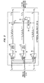
- FIG. 3 illustrating an exemplary implementation of Differential Signal Multiplexer 16 of FIG. 1, synchronized digital signals X a to X c from A/D converters 13-15, respectively, are terminated on a separate input of each of three switching means 30 to 32 such that each of the corresponding input terminals are connected to a different one of the three A/D converter 13-15 outputs. More particularly, the outputs from A/D converters 13-15 are connected to (a) the top, middle and bottom input terminals of switching means 30, respectively, (b) the middle, bottom and top input terminals of switching means 31, respectively, and (c) the bottom, top and middle input terminals of switching means 32, respectively.
- the three switching means 30-32 are arranged to move in synchronism from their top positions, to the middle position, to the bottom position, and back to the top position, etc.
- Switching means 30-32 also all change positions simultaneously preferably sometime during a vertical blanking period in such a way that complete fields of the input T V signals are routed to either the top, middle or bottom paths 33-35, respectively, at the output of switching means 30-32.
- the top path 33 contains a delay means 36 which provides a delay of exactly one frame period of the exemplary NTSC signal.
- the middle path 31 contains a delay means 37 which provides a delay of approximately one field period of the exemplary NTSC signal.
- switch 30 allows the field 1 signal (F la ) from source 10 (source “a”) to enter delay means 36.
- F 1 field 1 signal
- switch 30 allows the field 1 signal (F la ) from source 10 (source “a”) to enter delay means 36.
- F 2a second field from source 10
- switch 30 allows the field 1 signal (F la ) from source 10 (source "a") to enter delay means 36.
- F 2a second field from source 10
- switch 30 when switching means 30-32 connect their bottom terminals to each output, a third field (F 3a ) from source 10 (source "a”) enters path 35 while concurrent therewith the first and second fields from source 10 exit from delay means 36 and 37, respectively.
- This description can similarly be applied to three fields from each of sources 11 and 12.
- a predictor 38 is responsive to the output from switching means 32 on path 35 and produces the peak-limited predictions P' X1 and P' X2 defined in Equation (1). Details of an exemplary arrangement of predictor 38 are shown in FIG. 6. Essentially, predictor 38 comprises a 912-pel tapped delay line 50, a first and a second arithmetic logic circuit 52 and 53 which computes P X1 and PX2 respectively, and, finally, a first and a second peak clipping circuit 55 and 56 to ensure that the predictions P X1 and PX2 , respectively, fall in the same range as the original pels.
- the taps from tapped delay line 50, used by the logic circuits 52 and 53, are in accordance with the appropriate one of Eq. (1).
- the outputs P' X1 and P' X2 from predictor 38 are subtracted in subtractors 39 and 40, respectively, from the respective outputs of delay means 36 and 37 to provide the F I -F 3 and F 2 -F 3 differential signals, respectively.
- the three output signals Y 1 -Y 3 from FIG. 3 are then transmitted to Time Compression Multiplexer 17 shown in greater detail in F IG. 7.
- the three output signals derived from the field signals of FIG. 4 are shown in FIG. 5.
- Time Compression Multiplexer 17 The purpose of Time Compression Multiplexer 17 is to combine the three signals (Y i , Y 2 and Y 3 ) from the Differential Signal Multiplexer 16 into a single signal, hereinafter designated Z.
- Time Compression Multiplexer 17 time compresses the three inputs over every T -second period into a single output with the same duration.
- Such function can be achieved as shown in FIG. 7 by writing each of the digital words Y l -Y 3 into a separate random access memory (RAM) 60-62 at one speed and reading these words out at a faster speed. Such operation is shown pictorially in FIGs. 8 and 9, where FIG.
- FIG. 8 shows the inputs Y 1 -Y 3 to Time Compression Multiplexer 17 and each of RAMs 60-62, respectively, and FIG. 9 shows the time compressed output signal Z from Multiplexer 17 during one time period shown in FIG. 5.
- the ratio of the read clock rate to the write clock rate for the RAMs 60-62 is the time compression factor, which should be greater than 1 for time compression. Since the time compression is to be done over a T-second period, one solution would be to write all of the Y i signals into the associated RAMs 60-62 for the field period before reading them out appropriately for multiplexing. However, such solution would require the RAMs to accommodate entire fields of signals. Instead, it is proposed here that time compression be done over a TV scan-line interval (approximately 63.6 microseconds) so that only line memories are needed.
- T' is the original 4.2 MHz bandwidth TV
- Y 1 and Y 2 are each a 2 MHz bandwidth differential signal
- T in the output Z is the processing delay.
- the T'-second line of Y 3 is time compressed by a factor of ⁇ ( ⁇ >1) so that the resultant signal occupies T l seconds (T, ⁇ T').
- Y 1 and Y 2 are both compressed by ⁇ ( ⁇ >1) so that each of their resultants occupies T 2 seconds (T 2 ⁇ T 1 ⁇ T'). It is required that these three time compressed signals be contained in T', i.e.,
- the factor 0.83 is due to the deletion of the differential signal horizontal blanking intervals, which are identically zero and need not be sent. The above simplifies to
- f 3 , f 2 and f l are the maximum frequencies of Y 3 , Y 2 and Y 1 , respectively.
- f 3 4.2 MHz
- solutions to (3) and (4) are
- T 1 ⁇ 0.56T' and T 2 -0.22T' The maximum frequency of the combined output is given by Eq. (4) and is 7.52 MHz, as compared to 12.6 MHz obtained in a straightforward TCM of the three T V s.
- the T CM bandwidth has been minimized by the deletion of the horizontal blanking intervals in the differential signals and also the equal setting of all time compressed signal bandwidths as shown in Eq. (4).
- the time compressed outputs Y 1 and Y 2 from RAMs 60 and 61 are time multiplexed in multiplexer 63 and transmitted through an Amplitude Compandor 64.
- the differential signals are chosen such that their amplitudes are small compared to the original signal on the average.
- the Amplitude Compandor 64 serves to compress the large voltage levels of the differential signals so as to make better use of the FM deviation. This has been found to be very useful to suppress the effect of transmission noise on picture quality.
- the time compressed and amplitude companded differential signals Y l and Y 2 are multiplexed with the time compressed field signal Y 3 from RAM 62 in a multiplexer 65 to generate the output signal Z.
- the present system takes three NTSC TV signals and combines them into a 7.52 MHz, or 8.4 M H z, signal for transmission.
- the multiplexing technique is TCM, and the bandwidth reduction is the result of the use of differential signals.
- the transmission format is three fields from one TV source compressed into one ordinary field period.
- the transmission to, for example, a satellite of a satellite communication system is switched sequentially between the three TV sources at a rate equal to the field or vertical scanning frequency of ordinary NTSC TV (approximately 60 H z). If the three TV sources are synchronized with one another, then the transmitter/multiplexer requires only three field memories. Otherwise, additional memory is needed for synchronization. In either case, the receiver requires only three field memories, as will be shown hereinafter.
- each producing stereo audio a total of six audio waveforms must be transmitted.
- Sending the stereo audio from each source along with its video by inserting digital audio in either the vertical or horizontal blanking periods is here suggested.
- the audio signals may be included in some convenient segment of the vertical blanking period. This of course will lead to a slightly more stringent timing requirement as well as some additional buffer memory.
- the audio be sampled exactly twice the TV line scan rate, yielding a total of six samples or 60 bits from the three scan lines for transmission in the prescribed time compressed horizontal blanking period.
- twenty multilevel pulses could be used to represent the 60-bit information.
- the six audio samples from the three lines plus another pulse for bit timing would just fill the 2.7 ⁇ sec time slot.
- TCM Time Division Multiple Access
- each transmit earth station needs only two field memories (instead of three) to generate the differential signals required.
- the input switches in FIG. 3 are also unnecessary. A similar saving in receiver memory is possible too if only one TV is to be received in a downlink earth station.
- the present invention can also be performed using one field signal as is and two field differential signals.
- the field differential signals might be defined as: where where
- FIGs. 11 and 12 An arrangement for implementing the Differential Signal Multiplexer 16 of FIG. 1 to generate a baseband field signal, as is, and two field differential signals is shown in FIGs. 11 and 12, which is similar to the arrangements shown in FIGs. 3 and 6.
- the switching means 30-32 and delay means 36 and 37 function as described for the corresponding elements in FIG. 3.
- predictor 70 receives the delayed field signal in path 34, corresponding to the middle field signal of the three field sequence used for transmission purposes, and generates therefrom, a first peak limited prediction, P' X1 , and a second peak limited prediction, P'X 3 .
- the first prediction is used in subtractor 39 to produce the field differential signal F l -F 2 in path 33 while the second prediction is used in a subtractor 71 in path 35 to generate the second field differential signal F 3 -F 2 for transmission to Time Compression Multiplexer 17.
- FIG. 12 A typical arrangement for predictor 70 to implement Eq. (6) is shown in FIG. 12 and is similar to the arrangement shown in FIG. 6 except that logic circuits 52 and 53 of FIG. 6 must be modified to the arrangements 73 and 74, respectively, shown in FIG. 12. Furthermore, to accommodate the output signals Y I -Y 3 from FIG. 11, Time Compression Multiplexer 17 shown in FIG. 7 should be modified to input the Y 2 signal on path 34 of FIG. 11 into RAM 62 of FIG. 7, and the Y 3 signal on path 35 of FIG. 11 into RAM 61 of FIG. 7.
- FIG. 13 shows an exemplary Receiver for receiving the signals transmitted by the Transmitter of FIG. 1 as shown in FIG. 9.
- the received FM waveform is demodulated in FM receiver 80 to recover the TCM baseband waveform.
- the demodulated signal is then digitized, if necessary, in optional A/D converter 81 to generate the signal Z' which would be identical to signal Z of FIG. 1 except for the transmission noise and channel distortion added. If suitable analog circuitry is available for processing the demodulated signal as explained heretofore for A/D Converters 13-15 of FIG. 1, then Converter 81 of FIG. 13 can be avoided.
- An amplitude compandor 82 is used to undo the companding done to the composite waveform in Amplitude Compandor 64 of FIG. 7.
- the three segments in this waveform comprising the original field signal and the two differential signals, are then separated by a demultiplexer 83 and written into three separate random-access-memories (RAMs) 84-86 at a first predetermined speed.
- the three signals are read out of RAMs 84-86 at slower speeds in order that these signals be expanded to the full scan line length.
- the expansion factors, the ratio of write clock rate to read clock rate, are precisely the compression factors used in the transmitter by RAMs 60-62 in FIG. 7. Approximations to Y ll Y 2 and Y 3 , denoted with a prime, are then obtained.
- predictor 87 is used to convert the differential signals into the original field signals.
- predictor 87 is shown disposed as the predictor 38 of F IG. 3 to recover the original fields from the field and frame differential signals generated by the arrangement of FIG. 3. More particularly, predictor 87 generates the peak limited predictions P' X1 and P' X2 as shown in FIG. 6. Prediction P' X1 is then added to the Yi signal from RAM 84 in adder 88 to recover the original first field signal, and prediction P X is added to the Y2 signal from RAM 85 in adder 89 to recover the original second field signal. It is to be understood that predictor 87 would have to be connected differently if two field differential signals or a different frame and field differential signal were originally transmitted.
- the output from adder 89 is delayed for approximately one field period in field delay means 90 while the output from RA M 86 is delayed for approximately one frame period in frame delay means 91.
- the three output switching means 93-95 are disposed in the top, middle and bottom paths, respectively, in FIG. 13 and function, similar to that described for switching means 30-32 of FIG. 3, to route the output digital signals of the original fields to their appropriate outputs. It is to be understood that the output switching means 93-95 move in synchronism from the top position to the middle position, to the bottom position, and back to the top position, etc.
- the output digital signals may, or may not, then be converted to analog signals in optional D/A converters 96-98 for display or local distribution.
Landscapes
- Engineering & Computer Science (AREA)
- Multimedia (AREA)
- Signal Processing (AREA)
- Color Television Systems (AREA)
- Television Systems (AREA)
- Time-Division Multiplex Systems (AREA)
Applications Claiming Priority (2)
| Application Number | Priority Date | Filing Date | Title |
|---|---|---|---|
| US500954 | 1983-06-03 | ||
| US06/500,954 US4593318A (en) | 1983-06-03 | 1983-06-03 | Technique for the time compression multiplexing of three television signals |
Publications (3)
| Publication Number | Publication Date |
|---|---|
| EP0130693A2 true EP0130693A2 (fr) | 1985-01-09 |
| EP0130693A3 EP0130693A3 (en) | 1986-04-16 |
| EP0130693B1 EP0130693B1 (fr) | 1991-02-27 |
Family
ID=23991566
Family Applications (1)
| Application Number | Title | Priority Date | Filing Date |
|---|---|---|---|
| EP84303626A Expired - Lifetime EP0130693B1 (fr) | 1983-06-03 | 1984-05-30 | Procédé et dispositif pour le multiplexage à compression de temps de trois signaux de télévision |
Country Status (5)
| Country | Link |
|---|---|
| US (1) | US4593318A (fr) |
| EP (1) | EP0130693B1 (fr) |
| JP (1) | JPS6019375A (fr) |
| DE (1) | DE3484151D1 (fr) |
| ES (1) | ES8503465A1 (fr) |
Families Citing this family (42)
| Publication number | Priority date | Publication date | Assignee | Title |
|---|---|---|---|---|
| NL8501096A (nl) * | 1985-04-15 | 1986-11-03 | Philips Nv | Televisiesysteem en daartoe geschikte informatiegever en -ontvanger. |
| US4864566A (en) * | 1986-09-26 | 1989-09-05 | Cycomm Corporation | Precise multiplexed transmission and reception of analog and digital data through a narrow-band channel |
| US4816914A (en) * | 1987-01-07 | 1989-03-28 | Pictel Corporation | Method and apparatus for efficiently encoding and decoding image sequences |
| US4821101A (en) * | 1987-02-19 | 1989-04-11 | Isix, Inc. | Video system, method and apparatus |
| US4847690A (en) * | 1987-02-19 | 1989-07-11 | Isix, Inc. | Interleaved video system, method and apparatus |
| US4849810A (en) * | 1987-06-02 | 1989-07-18 | Picturetel Corporation | Hierarchial encoding method and apparatus for efficiently communicating image sequences |
| US5767913A (en) * | 1988-10-17 | 1998-06-16 | Kassatly; Lord Samuel Anthony | Mapping system for producing event identifying codes |
| US5790177A (en) * | 1988-10-17 | 1998-08-04 | Kassatly; Samuel Anthony | Digital signal recording/reproduction apparatus and method |
| US5508733A (en) * | 1988-10-17 | 1996-04-16 | Kassatly; L. Samuel A. | Method and apparatus for selectively receiving and storing a plurality of video signals |
| US5691777A (en) * | 1988-10-17 | 1997-11-25 | Kassatly; Lord Samuel Anthony | Method and apparatus for simultaneous compression of video, audio and data signals |
| US4903126A (en) * | 1989-02-10 | 1990-02-20 | Kassatly Salim A | Method and apparatus for tv broadcasting |
| US6493878B1 (en) | 1988-10-17 | 2002-12-10 | Lord Samuel A Kassatly | Method and apparatus for tv broadcasting and reception |
| US5768517A (en) * | 1988-10-17 | 1998-06-16 | Kassatly; Samuel Anthony | Paperless publication distribution and retrieval system |
| US5157491A (en) * | 1988-10-17 | 1992-10-20 | Kassatly L Samuel A | Method and apparatus for video broadcasting and teleconferencing |
| US6124882A (en) * | 1992-02-19 | 2000-09-26 | 8×8, Inc. | Videocommunicating apparatus and method therefor |
| US4995036A (en) * | 1989-08-07 | 1991-02-19 | General Dynamics Land Systems, Inc. | Multichannel data compressor |
| US7594250B2 (en) * | 1992-04-02 | 2009-09-22 | Debey Henry C | Method and system of program transmission optimization using a redundant transmission sequence |
| US5421031A (en) * | 1989-08-23 | 1995-05-30 | Delta Beta Pty. Ltd. | Program transmission optimisation |
| DE69030886T2 (de) * | 1989-08-23 | 1998-03-05 | Delta Beta Pty. Ltd., Fremantle, W.A. | Optimisierung einer programmübertragung |
| US5027207A (en) * | 1989-09-21 | 1991-06-25 | Japan Business Television, Inc. | Television signal transmission system utilizing TDMA technique |
| KR930000956B1 (ko) * | 1989-12-31 | 1993-02-11 | 삼성전자 주식회사 | 복수개의 비데오신호 기록 및 재생 제어장치 |
| US5164980A (en) * | 1990-02-21 | 1992-11-17 | Alkanox Corporation | Video telephone system |
| US5347305A (en) * | 1990-02-21 | 1994-09-13 | Alkanox Corporation | Video telephone system |
| JPH03283831A (ja) * | 1990-03-30 | 1991-12-13 | Shiyoudenriyoku Kosoku Tsushin Kenkyusho:Kk | 移動通信方式 |
| US5253275A (en) | 1991-01-07 | 1993-10-12 | H. Lee Browne | Audio and video transmission and receiving system |
| US5193000A (en) * | 1991-08-28 | 1993-03-09 | Stereographics Corporation | Multiplexing technique for stereoscopic video system |
| US5416510A (en) * | 1991-08-28 | 1995-05-16 | Stereographics Corporation | Camera controller for stereoscopic video system |
| US6121998A (en) * | 1992-02-19 | 2000-09-19 | 8×8, Inc. | Apparatus and method for videocommunicating having programmable architecture permitting data revisions |
| GB2264838B (en) * | 1992-02-21 | 1995-08-30 | Samsung Electronics Co Ltd | Video recording apparatus |
| JPH06284392A (ja) * | 1993-03-30 | 1994-10-07 | Toshiba Corp | 映像信号送受信装置 |
| US5412426A (en) * | 1993-04-16 | 1995-05-02 | Harris Corporation | Multiplexing of digitally encoded NTSC and HDTV signals over single microwave communication link from television studio to tower transmitter facility for simultaneous broadcast (simulcast) to customer sites by transmitter facility |
| US5461619A (en) * | 1993-07-06 | 1995-10-24 | Zenith Electronics Corp. | System for multiplexed transmission of compressed video and auxiliary data |
| US5455626A (en) * | 1993-11-15 | 1995-10-03 | Cirrus Logic, Inc. | Apparatus, systems and methods for providing multiple video data streams from a single source |
| US6975685B1 (en) * | 2000-10-24 | 2005-12-13 | Agere Systems Inc. | Apparatus and method for multi-channel communications system |
| US20110149811A1 (en) | 2009-12-23 | 2011-06-23 | Ramprakash Narayanaswamy | Web-Enabled Conferencing and Meeting Implementations with Flexible User Calling Features |
| US8914734B2 (en) | 2009-12-23 | 2014-12-16 | 8X8, Inc. | Web-enabled conferencing and meeting implementations with a subscription-based model |
| US20110150194A1 (en) | 2009-12-23 | 2011-06-23 | Ramprakash Narayanaswamy | Web-Enabled Conferencing and Meeting Implementations with Flexible User Calling Features |
| US20110149809A1 (en) | 2009-12-23 | 2011-06-23 | Ramprakash Narayanaswamy | Web-Enabled Conferencing and Meeting Implementations with Flexible User Calling and Content Sharing Features |
| US8817801B1 (en) | 2011-07-08 | 2014-08-26 | 8X8, Inc. | Conferencing and meeting implementations with advanced features |
| US10623692B2 (en) | 2018-07-13 | 2020-04-14 | Analog Devices Global Unlimited Company | High definition analog video and control link for automotive applications |
| US10855951B2 (en) | 2018-07-13 | 2020-12-01 | Analog Devices Global Unlimited Company | Methods and devices for compensating sag effect |
| US10462413B1 (en) | 2018-10-26 | 2019-10-29 | Analog Devices Global Unlimited Company | Using metadata for DC offset correction for an AC-coupled video link |
Family Cites Families (6)
| Publication number | Priority date | Publication date | Assignee | Title |
|---|---|---|---|---|
| US4161629A (en) * | 1978-02-06 | 1979-07-17 | Raytheon Company | Communication system with selectable data storage |
| JPS55120279A (en) * | 1979-03-12 | 1980-09-16 | Hitachi Denshi Ltd | Still picture transmitter |
| JPS5811148B2 (ja) * | 1979-10-05 | 1983-03-01 | 株式会社 東京放送 | 2チヤンネル映像信号伝送方式 |
| US4302838A (en) * | 1980-03-03 | 1981-11-24 | Bell Telephone Laboratories, Incorporated | Apparatus for synchronizing an input signal with a time multiplexed signal |
| US4300161A (en) * | 1980-03-03 | 1981-11-10 | Bell Telephone Laboratories, Incorporated | Time compression multiplexing of video signals |
| US4410981A (en) * | 1981-01-28 | 1983-10-18 | Rca Corporation | Simplified transmission system for sequential time-compression of two signals |
-
1983
- 1983-06-03 US US06/500,954 patent/US4593318A/en not_active Expired - Fee Related
-
1984
- 1984-05-30 DE DE8484303626T patent/DE3484151D1/de not_active Expired - Fee Related
- 1984-05-30 EP EP84303626A patent/EP0130693B1/fr not_active Expired - Lifetime
- 1984-06-01 ES ES533073A patent/ES8503465A1/es not_active Expired
- 1984-06-02 JP JP59112227A patent/JPS6019375A/ja active Pending
Non-Patent Citations (3)
| Title |
|---|
| BELL SYSTEM TECHNICAL JOURNAL, vol. 60, no. 5, May-June 1981, pages 643-660, American Telephone and Telegraph Co., New York, US; B.G. HASKELL: "Time-frequency multiplexing (TMF) of two NTSC color TV signals-simulation results" * |
| BELL SYSTEM TECHNICAL JOURNAL, vol. 61, no. 10, December 1982, Part 1, pages 2917-2927, American Telephone and Telegraph Co., Murray Hill, New Jersey, US; K.Y. ENG et al.: "TV bandwidth compression techniques using time-companded differentials and their applications to satellite transmissions" * |
| BELL SYSTEM TECHNICAL JOURNAL, vol. 62, no. 10, December 1983, Part 1, pages 2853-2865, Murray Hill, New Jersey, US; K.Y. ENG et al.: "Time-compression multiplexing (TMC) of three broadcast-quality TV signals on a satellite transponder" * |
Also Published As
| Publication number | Publication date |
|---|---|
| ES533073A0 (es) | 1985-03-01 |
| JPS6019375A (ja) | 1985-01-31 |
| DE3484151D1 (de) | 1991-04-04 |
| ES8503465A1 (es) | 1985-03-01 |
| US4593318A (en) | 1986-06-03 |
| EP0130693B1 (fr) | 1991-02-27 |
| EP0130693A3 (en) | 1986-04-16 |
Similar Documents
| Publication | Publication Date | Title |
|---|---|---|
| EP0130693B1 (fr) | Procédé et dispositif pour le multiplexage à compression de temps de trois signaux de télévision | |
| US4885631A (en) | High resolution color television signal transmission system and receiver utilizing motion information of a picture | |
| US4745459A (en) | Divisionally time-compressed subsample transmission and motion-compensated reproduction system for a high definition color television picture signal | |
| US4794447A (en) | Method and apparatus for transmitting and receiving a high definition NTSC compatible television signal over a single DBS channel in time division multiplex form | |
| US4989091A (en) | Scan converter for a high definition television system | |
| KR870007623A (ko) | 합 및 차 성분을 갖는 순차 주사 텔레비전 시스템 | |
| US4967272A (en) | Bandwidth reduction and multiplexing of multiple component TV signals | |
| US4589110A (en) | Signal processor (system) for reducing bandwidth and for multiplexing a plurality of signals onto a single communications link | |
| WO1989012372A1 (fr) | Appareil d'enregistrement de television a definition etendue | |
| FI78207B (fi) | Transmissionssystem foer television samt saendar- och mottagningsanordning. | |
| US4630099A (en) | Time multiplexing chrominance information for compatible high-definition television | |
| US5053860A (en) | Method and apparatus for the transmission and reception multicarrier high definition television signal | |
| US4589018A (en) | Technique for the time frequency multiplexing on three television signals | |
| EP0148618A2 (fr) | Procédé et dispositif pour améliorer la reconstruction d'images vidéo dans un format de couleur à séquence de ligne | |
| US4633311A (en) | Signal processor (system) for reducing bandwidth and for multiplexing a plurality of signals onto a single communications link | |
| US4977454A (en) | HDNTSC channel with frequency multiplexing | |
| US5146327A (en) | Addition signal multiplexing apparatus for a television system | |
| GB2145610A (en) | Television transmission systems | |
| Eng et al. | Time‐Compression Multiplexing (TCM) of Three Broadcast‐Quality TV Signals on a Satellite Transponder | |
| US4646149A (en) | Alternate field luminance enhancement in a spectrum conserving television system | |
| EP0516359B1 (fr) | Dispositif de traitement d'un signal de télévision à grand écran | |
| EP0329976A2 (fr) | Système de télévision à composants analogiques multiples | |
| NL8702917A (nl) | Tv-omroepstelsel voor de overdracht van een hoogdefinitie tijdmultiplex tv-signaal. | |
| Lee et al. | Studio-quality videomultiplexer for satellite transmission | |
| JP3097403B2 (ja) | 映像信号送信装置と映像信号受信装置 |
Legal Events
| Date | Code | Title | Description |
|---|---|---|---|
| PUAI | Public reference made under article 153(3) epc to a published international application that has entered the european phase |
Free format text: ORIGINAL CODE: 0009012 |
|
| AK | Designated contracting states |
Designated state(s): DE FR GB NL |
|
| PUAL | Search report despatched |
Free format text: ORIGINAL CODE: 0009013 |
|
| AK | Designated contracting states |
Kind code of ref document: A3 Designated state(s): DE FR GB NL |
|
| 17P | Request for examination filed |
Effective date: 19860916 |
|
| 17Q | First examination report despatched |
Effective date: 19881102 |
|
| GRAA | (expected) grant |
Free format text: ORIGINAL CODE: 0009210 |
|
| AK | Designated contracting states |
Kind code of ref document: B1 Designated state(s): DE FR GB NL |
|
| REF | Corresponds to: |
Ref document number: 3484151 Country of ref document: DE Date of ref document: 19910404 |
|
| ET | Fr: translation filed | ||
| PLBE | No opposition filed within time limit |
Free format text: ORIGINAL CODE: 0009261 |
|
| STAA | Information on the status of an ep patent application or granted ep patent |
Free format text: STATUS: NO OPPOSITION FILED WITHIN TIME LIMIT |
|
| 26N | No opposition filed | ||
| PGFP | Annual fee paid to national office [announced via postgrant information from national office to epo] |
Ref country code: DE Payment date: 19920421 Year of fee payment: 9 |
|
| PGFP | Annual fee paid to national office [announced via postgrant information from national office to epo] |
Ref country code: FR Payment date: 19920423 Year of fee payment: 9 |
|
| PGFP | Annual fee paid to national office [announced via postgrant information from national office to epo] |
Ref country code: GB Payment date: 19920424 Year of fee payment: 9 |
|
| PGFP | Annual fee paid to national office [announced via postgrant information from national office to epo] |
Ref country code: NL Payment date: 19920531 Year of fee payment: 9 |
|
| PG25 | Lapsed in a contracting state [announced via postgrant information from national office to epo] |
Ref country code: GB Effective date: 19930530 |
|
| PG25 | Lapsed in a contracting state [announced via postgrant information from national office to epo] |
Ref country code: NL Effective date: 19931201 |
|
| NLV4 | Nl: lapsed or anulled due to non-payment of the annual fee | ||
| GBPC | Gb: european patent ceased through non-payment of renewal fee |
Effective date: 19930530 |
|
| PG25 | Lapsed in a contracting state [announced via postgrant information from national office to epo] |
Ref country code: FR Effective date: 19940131 |
|
| PG25 | Lapsed in a contracting state [announced via postgrant information from national office to epo] |
Ref country code: DE Effective date: 19940201 |
|
| REG | Reference to a national code |
Ref country code: FR Ref legal event code: ST |