EP0130738B1 - Niveau électronique - Google Patents
Niveau électronique Download PDFInfo
- Publication number
- EP0130738B1 EP0130738B1 EP84304171A EP84304171A EP0130738B1 EP 0130738 B1 EP0130738 B1 EP 0130738B1 EP 84304171 A EP84304171 A EP 84304171A EP 84304171 A EP84304171 A EP 84304171A EP 0130738 B1 EP0130738 B1 EP 0130738B1
- Authority
- EP
- European Patent Office
- Prior art keywords
- radiation
- chamber
- bubble
- orientation
- output
- Prior art date
- Legal status (The legal status is an assumption and is not a legal conclusion. Google has not performed a legal analysis and makes no representation as to the accuracy of the status listed.)
- Expired
Links
Images


Classifications
-
- G—PHYSICS
- G01—MEASURING; TESTING
- G01C—MEASURING DISTANCES, LEVELS OR BEARINGS; SURVEYING; NAVIGATION; GYROSCOPIC INSTRUMENTS; PHOTOGRAMMETRY OR VIDEOGRAMMETRY
- G01C9/00—Measuring inclination, e.g. by clinometers, by levels
- G01C9/02—Details
- G01C9/06—Electric or photoelectric indication or reading means
-
- G—PHYSICS
- G01—MEASURING; TESTING
- G01C—MEASURING DISTANCES, LEVELS OR BEARINGS; SURVEYING; NAVIGATION; GYROSCOPIC INSTRUMENTS; PHOTOGRAMMETRY OR VIDEOGRAMMETRY
- G01C9/00—Measuring inclination, e.g. by clinometers, by levels
- G01C9/18—Measuring inclination, e.g. by clinometers, by levels by using liquids
- G01C9/24—Measuring inclination, e.g. by clinometers, by levels by using liquids in closed containers partially filled with liquid so as to leave a gas bubble
- G01C9/26—Details
- G01C9/28—Mountings
Definitions
- This invention relates to an orientation indicating apparatus useful for indicating the orientation of spirit levels, survey sighting apparatus or any member whose orientation is desired.
- Known spirit levels used in the building industry to test the orientation or level of structural and other members include a liquid charged tube with an air or gas bubble contained therein.
- the tube is generally made of glass or transparent plastics material.
- the bubble occupies a central portion in the tube and may be flanked by spaced equidistant reference lines.
- the tube may be charged with a liquid having particular sensitivity to movement, and the bubble may be elongated to further enhance the sensitivity to movement.
- a liquid may be unstable with ambient temperature variations, and the bubble may locate within a series of graduations marked on the surface of the tube when in the level condition. Direct visual observation by the operator may, under these conditions give an inaccurate level reading.
- US-A-4,182,046 discloses an orientation indicating apparatus including a liquid charged chamber having a bubble movable in the chamber as the orientation of the chamber is changed.
- Two photodiodes illuminate the bubble laterally from one side thereof and their radiation which either passes transversely through the bubble or transversely to its line of movement is picked up by two detectors mounted on the opposite side of the bubble and chamber to the photodiodes.
- the radiation signals received by the detectors are compared to determine the orientation of the chamber. This location of the photodiodes and detectors laterally or transversely of the bubble reduces the sensitivity of the apparatus, because of the different angles of radiation received by the detectors depending upon whether or not the radiation passes through or alongside the bubble, and reduces the range of orientation positions detectable.
- AU-A-490836 discloses an orientation indicating apparatus in which two light emitting diodes may be arranged one at each of opposite ends of the chamber and bubble so that light is deflected laterally from both ends edges of the bubble.
- Two detecting means of unspecified position, may be provided to provide a net or sum total evaluation of light intensity received to determine when maximum intensity of light is impinging on the two detecting means.
- the signals from the two light emitting diodes are not compared but are added only and hence this apparatus cannot determine direction and magnitude of deviation of the bubble from a predetermined orientation.
- orientation indicating apparatus including a liquid charged chamber having a bubble movable within the chamber as orientation of the chamber is changed, radiation emitting means operable to emit radiation into the chamber, radiation detecting means to detect radiation from the radiation emitting means, and signal comparing means for comparing the values of the radiation signals received by the radiation detecting means, characterised in that said radiation emitting means are operable to emit radiation into the chamber along paths which are located generally along the line of movement of the bubble to impinge substantially on two end edges of the bubble and be reflected laterally from those two end edges, said radiation detecting means are operable to detect radiation reflected laterally from the two end edges at least when the chamber is in a predetermined orientation and to generate respective intensity signals which are variable with movement of the bubble and indicative of the reflected radiation intensity detected from the two end edges when the bubble is in said predetermined position and substantially throughout a continuous range of possible positions of the two end edges of the bubble, and said signal comparing means are operable to receive the two intensity signals and continuously to compare said signals to determine direction and magnitude
- orientation of a level or other sighting apparatus or member may be determined without the need for direct visual observation by the user.
- the radiation emitting means is operable to emit substantially equal intensity radiation beams into the chamber to impinge on the two end edges of the bubble which are symmetrically located relative to the bubble centre, the radiation detecting means being located relative to the bubble position when the chamber is in said predetermined orientation so as to receive equal intensities of radiation reflecting from said end edges, and wherein said signal comparing means is operable to compare the two intensity signals so as to detect when the signals are balanced.
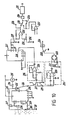
- Figure 1 shows a circuit for an orientation apparatus according to an embodiment of the invention.
- Module unit 67 is associated with indicating means for providing visual and audible indication of the level of the vial 1.
- the module includes a liquid containing chamber or vial 1 which contains a bubble 2 preferably of air.
- Light- emitting diodes 3 and 4 which emit infra-red radiation are positioned against the end walls of the vial and emit radiation into these ends along paths which are located generally along the line of movement of the bubble 2 to impinge on bubble edges 3A and 4A.
- Current limiting resistors 5 and 6 are connected between the cathode electrodes of the diodes and a reference potential. These resistors typically limit the current to 1.5 miliamp.
- Each diode has its anode electrode connected to a supply or positive potential.
- Two phototransistors 7 and 8 are positioned on one side of the module opposite the bubble. When the bubble is centrally located these phototransistors (which may be MEL12 type) have their collector electrodes connected to a supply of positive potential shown as +V. The emitter electrodes of these transistors are connected via resistors 8 and 10 respectively to a reference potential. As the result of current flowing through the transistors, when radiation impinges upon the base electrodes, this causes a voltage potential to be developed across resistors 9 and 10. These voltage potentials are applied to inputs 12 and 13 of differential amplifier 14. Amplifier 14 has a series combination of resistor 16 and adjusting resistor 15 connected between its output and input terminal 12.
- Resistors 15 and 16 form a gain adjusting means be an integrated circuit amplifier type 741.
- the amplifier is connected to positive and negative supply as indicated.
- the output of amplifier 14 is coupled to differential meter 18 via resistor 17.
- Meter 18 which reads zero volts at its centre position has a needle which may deflect to the left hand side or the right hand side as a consequence of receiving positive or negative voltage inputs from the amplifier 14.
- Resistor 19 is coupled between the output of amplifier 14 and to two oppositely poled light emitting diodes 20 and 21. The anode of diode 20 and the cathode of diode 21 are connected to a reference potential.
- These light emitting diodes are thus connected between the output of amplifier 14 and a reference potential, and as the amplifier provides a positive voltage output light emitting diode 21 will light up.
- the amplifier 14 provides a negative voltage output light emitting diode 21 is not energised and light emitting diode 20 lights up.
- bubble movement in either the left or right hand direction provides a visual indication on meter 18 and illuminates one or other of light emitting diodes 20 and 21. If desired light emitting diodes 20 and 21 may be of different colours.
- Meter 18 may also evaluate the electrical difference after amplification of the signals provided by phototransistors 7 and 8 and can, for example give a gradual rising or falling reading before amplification 7 and 8 saturation occurs.
- the diodes 20 and 21 and/or the meter 18 may be located remote from the bubble 2 and vial 1 and connected to the latter by cable or radio link.
- the inputs of the differential amplifier 14 are balanced and no output is provided by the amplifier. Displacement of the bubble 2 causes the input currents to become imbalanced and, depending upon the amount of displacement and the gain setting of the amplifier 14, the amplifier can be driven into saturation producing a maximum voltage at its output.
- a certain amount of elevation of the left hand end of the vial causes the right hand edge of the bubble 2 to move away from the right hand phototransistor 7.
- This phototransistor receives a decrease in illumination due to the bubble edge 3a moving away therefrom.
- the left hand phototransistor 8 receives illumination from the left hand bubble edge 4a which is receding therefrom and also from the approaching right hand bubble edge 3a. This provides an imbalance of the electrical currents produced by the phototransistors, thus causing a positive or negative voltage output to be present at the amplifier output, the polarity of the output being indicative of the direction of movement of the bubble 2.
- the amplifier 14 may register an output on minute changes of orientation of the module. These changes may not be optically discernible by an operator using the apparatus in a comparable manual exercise. Where the module is subject to vibrations and the bubble edges experience minute rapid fluctuations the period of vibration may be found by connecting the output of the amplifier 14 into a phase comparator 39.
- the comparator 39 may also be connected to a variable frequency generator 41. By sweeping the generator through a range of frequencies a point in the phase comparator may be reached where the vibrational frequency corresponds to the output of the frequency generator and the output of the comparator will then be indicative of a match between the vibrational frequency and the frequency of the generator.
- the output of amplifier 14 is connected via resistor 22 to oscillators 23 and 24.
- Oscillators 23 and 24 are activated respectively by positive and negative voltages appearing at the amplifier out- putThe outputs of oscillators 23 and 24 are coupled to speaker 26 via audio amplifier 25.
- the oscillators 23 and 24 provide outputs at 600 Hz and 400 Hz respectively.
- the 400 Hz oscillator may produce an audible signal at the speaker.
- a 600 Hz sound may be produced when the bubble moves to the left and a 400 Hz sound when it moves to the right.
- the frequency of the sound produced at the speaker 26 may be increased incremetally as the bubble 2 moves.
- a higher or lower frequency sound may be produced as the bubble 2 moves.
- the visual or audible signals produced which are indicative of bubble movement may be transmitted either by cable radio or other link to a remote monitoring station.
- Typical components values for oscillators 23 are as follows:-
- Transistors 25 and 26 are NPN transistors, collector resistor 27 may be 10K ohms, resistors 28 and 29 are 1K ohms, resistor 30 is 100K ohms, capacitors 31 and 32 are 0.01 mfd.
- Oscillator 24 may have identical components to that of oscillator 23 except that the transistors are PNP type and resistor 33 is 200K ohms.
- Transistors 34 and 35 may be BC178 types.
- Transistors 25 and 26 may be BC208 types. To evaluate the frequency of vibrations to which the module may be subjected (these vibrations will result in rapid fluctuations of the output provided by amplifier 14) the circuit of Figure 2 may be employed.
- Amplifier 36 of Figure 2 receives as its inputs the outputs of photo- transistors 7 and 8.
- a series combination of resistors is connected between one of the inputs and the output of amplifier 36. The purpose of these resistors is the same as that of resistors 15 and 16 of Figure 1.
- the amplifier 36 has its output coupled via capacitor 37 to AND gate 38.
- Gate 38 has its output coupled to the clock input of flip flop 39.
- a variable frequency generator 41 is connected via AND gate to the D input of flip flop 39.
- the Q output of flip flop 39 (terminal 46 in Figure 2) is connected to audioamplifier 42 and speaker 43.
- the TS terminals 44 and 45 of flip flop 39 are connected to a reference potential.
- Flip flop 39 acts as a sensitive phase comparator. The frequency of generator 41 until a zero beat is heard at the speaker 43. If desired the Q output 46 of flip flop 39 may be used to energise light emitting diodes or a digital display (not shown) to indicate phase variation.
- Capacitors 48 and 49 are input capacitors which connect across the light-emitting diodes. One terminal of each capacitor is connected to terminals 64 and 65 of the module and these allow a common frequency source 50 to be connected thereto.
- Phototransistors 51 and 52 have switches 53 and 54 connected to their emitter electrodes. In one position of these switches the emitter electrodes are connected via capacitors 55 and 56 to the inputs of differential amplifier 63 after passing through transformers 57 and 59.
- Transformers 57 and 59 have rectifier bridges 58 and 60 connected to the secondary windings. These bridges convert the alternating current signal of the secondary windings to a DC signal. These DC signals may be applied directly via switches 61 and 62 to the inputs of the amplifier 63. Thus, when the switches in the module are set for AC operation and a common source of frequency is applied to terminals 64 and 65 of the module the AC signal produced by the phototransistors after they receive radiation from the edge of the bubble is coupled to the rectifier bridges via transformers 57 and 59 and then to the differential amplifier.
- the transformers 57 and 59 may be made receptive to a certain frequency injected at the module terminals 64 and 65. Different frequency signals may be injected into each of the photodiodes to illuminate the bubble edges, and thus each phototransistor becomes receptive to its own source of illuminating radiation.
- the left hand edge 4a of the bubble 2 may give off radiation modulated by 1 KHz frequency whilst the right hand edge 3a may give off a 20KHz frequency whilst the right hand edge 3a may give off a 20KHz modulated radiation.
- the detecting means provide outputs at these frequencies and these outputs are connected to the flip-flop 39.
- Such an arrangement provides for very sensitive detection of radiation from the edges of the bubble.
- the operation of the switches in one of their positions connects the signal provided by the photo-transistors to the inputs of the differential amplifier. It will be evident that this process of frequency rejection causes the detection of the bubble edge to be frequency selective.
- the module may be transparent and ambient light will not affect the operation of the apparatus.
- the frequency- selective bubble edge detection is the electrical equivalent of operating the photo-transistors through a light-restricting aperture in the module housing. If the edges of the bubble are illuminated with radiation of different frequencies detection of the bubble edges becomes very selective in operation.
- the differential amplifier used in the various embodiments of the invention produces an output only when the edges of the bubble cause different amounts of radiation to be detected by the detecting phototransistors. Changes in bubble size by contraction or expansion due to ambient temperature variations do not produce an output signal at the differential amplifier since such variations in bubble size when the bubble is centrally located affects both phototransistors equally and thus the balanced position is preserved and no difference is detected. This feature provides for temperature immunity of the apparatus.
- Figure 4 shows what occurs with the apparatus of the invention when the bubble enlarges or contracts due to changes in temperature.
- the points of maximum illumination 68 and 69 seen on the bubble edge have moved equal distances from the photodetectors 71 and 72, and their planes of maximum detection 73 and 74 respectively are also equally spaced from the edges of the bubble, and thus there is no alteration seen as a difference in radiation detected by the detectors, and hence no output may be registered by the differential amplifier.
- An enlarged bubble is shown at 83, and in this bubble the maximum points of illumination 75 and 76 have moved outside the planes of detection 77 and 78. Again, however, the original balance is preserved and no output may be present at the output of the differential amplifier.
- a bubble 84 is shown where a plane of detection 81 is inside the bubble and the other plane 82 is outside. This gives rise to an imbalance condition.
- the detector at plane 81 receives illumination from points 79 and 80 whilst the detector at plane 82 receives reduced illumination from only one bubble edge 79. Thus an output is produced by the differential amplifier. This situation may be turned to advantage to evaluate temperature from the bubble in Figure 5.
- a temperature evaluation of the bubble is obtained from the detecting means and is used to activate external indicators.
- the bubble 85 in Figure 5 with its points of maximum illumination at 86 and 87 activate phototransistors 88 and 89 whose outputs are applied to differential amplifier 93.
- the emitter of detector 88 is coupled via resistor 92 to the input of a second differential amplifier 95.
- Amplifier 95 is used to evaluate the temperature of the bubble.
- the other input of amplifier 95 is connected via potentiometer 94 to a source of reference potential. When the bubble is centrally located and the ambient temperature is 20°C the potentiometer may be adjusted until a zero output is produced by amplifier 95. This output is connected via resistor 96 to a meter 98. The other terminal of meter 98 is connected to ground.
- Meter 98 normally reads zero, and should the bubble expand or contact the difference value from the original potentiometer setting will be read on meter 98 which reading will be indicative of the temperature variation.
- Amplifier 95 is coupled via resistor 97 to oscillators 99 and 100.
- the outputs of the oscillators may be arranged for remote connection at 101. As mentioned previously, one of the oscillators may produce a 600 Hz signal whereas the other may produce a 400 Hz signal.
- the frequencies at which the oscillators oscillate may vary in accordance with the varying output voltage provided by amplifier 95. Precise evaluation of the temperature at a remote location may be using a frequency-to-voltage converter to enable temperature readings to be obtained.
- voltage-controlled oscillators may allow the frequencies of the signals to be gradually varied from a minimum to maximum.
- temperatures above and below ambient may be remotely ready by converting these temperature-related frequency signals into a digital signal using a frequency-to-digital converter.
- temperature read-out is of prime importance the liquid in the vial may be chosen so as to be especially temperature sensitive.
- the position of the bubble within the vial may be located using similar circuit to that described above.
- the input voltages of the second differential amplifier may be balanced with the variably-connected voltage reference source when the bubble centrally locates and the applied voltage may be read to give a reference reading, and may be re-read after the bubble has moved and thus an indication of the bubble position can be obtained.
- the apparatus provides a means for bubble movement and variance of bubble position detection in which detection is independent of bubble enlargement or contraction caused by temperature variations.
- the bubble size variation due to temperature may be detected and evaluated, and bubble movement caused by orientation of a member may be indicated simultaneously with or in addition to a temperature evaluation.
- Figure 6 shows a circuit for providing operation of automatic levelling motors.
- the circuit includes logic switching means which allows a second level indication or automatic function to be activated on completion of a first evaluation.
- the circuit for operation of one levelling motor is shown within dotted outline 102.
- the vial 103 has light-emitting diodes 108 and 109 positioned at its ends. These diodes emit radiation which impinges on the edges of the bubble within vial 103.
- One source of maximum illumination impinging on the bubble is shown at 111. Radiation at the edges of the bubble is detected by phototransistors 105 and 104. The outputs from these transistors appear as a voltage potential developed across resistors 106 and 107. These output voltages are coupled to the inputs of differential amplifier 117.
- Amplifier 117 has gain- adjusting resistances connected in its feedback path between the output and the inverting input shown at 117A.
- the output of the amplifier is connected via resistor 118 to switch SW1 which is the up position as shown connects the resistor to switch contact 119 and then to the common of switching amplifying transistors 121 and 122.
- Transistors 121 and 122 are voltage amplifiers which have their operation limited by resistors in their emitter collector conduction paths. These transistors are complementary PNP and NPN transistors with their emitter electrodes connected together at 123. The emitter electrodes of these transistors are connected to the base electrodes ofthe main switching transistors 124 and 125.
- transistors in one embodiment of the invention are 2N3055 (NPN) and MJ2955 (PNP) and the transistors 121 and 122 may be 2N4250 (PNP) and 2N3569 (NPN). However, other types of transistors may also be used.
- the operation of switch SW1 to the down position bypasses the two preliminary switching transistors 121 and 122 thus connecting the amplifier output directly to the base electrodes of the main switching transistors 124 and 125.
- the collector electrodes of the main switching transistors are directly connected to the positive and negative supply voltages.
- a voltage protection circuit may be connected between the common connection of the emitter electrodes of transistors 124 and 125 and ground. These protection circuits protect the transistors from back emf produced by the levelling motor 134.
- the protection circuits comprise diodes 126 and 127 connected in series respectively with zener diodes 128 and 129. The other terminals of the zener diodes are connected to ground.
- the zener diodes may be chosen to be operative approximately at 4 volts higher than the supply voltage of the positive and negative supply. Thus, peak transients caused by the inductive circuit of the motor 134 are safely bypassed to ground.
- Switch SW 2 when operated to the down position connects the motor to switches 132 and 133 which in turn are coupled to the negative and positive supply respectively. The operation of these switches causes the motor to operate in either the reverse or forward direction of rotation thus lowering or raising the platform with which the motor may be associated.
- This circuit provides for automatic control of a sensing or levelling motor for controlling the raising or lowering of a platform.
- the output of the differential amplifier 117 swings positive or negative with respect to ground in synchronism with left and right hand movement of the bubble, the output of the amplifier 117 is connected in series with the motor 134.
- the motor 134 may be a permanent magnet DC motor which may be suitably attached to a housing containing the module.
- the motor 134 When the motor 134 is rotating in the forward direction it may with suitable mechanical coupling cause the module to be elevated at its right hand end extremity, and reverse-direction rotation of the motor may cause the module to be depressed or lowered at this extremity.
- a modification of this embodiment allows the apparatus of the invention to measure the amount of angular deviation of the module from the horizontal.
- the apparatus of the invention is placed upon a member to be measured, the apparatus is provided with a graduated degree scale over which a pointer fixed to the housing may read. Operation of the motor 134 gives a reading on the scale of the elevation or depression of a given reference point.
- the three modules may have their outputs connected to three actuating motors as has been described above.
- Additional circuitry may be connected between the outputs of the differential amplifiers and the motors. This circuitry may include switching means such as triacs and SCR's to operate AC or DC motors for automatic levelling of a member.
- two additional phototransistors 110 and 112 are shown positioned at a location halfway between the top and bottom surfaces of the vial and positioned to receive radiation from the bubble edge as shown at 111.
- the phototransistors 110 and 112 receive equal excitation from the bubble edge.
- These two phototransistors have their emitter resistances 113 and 114 connected to ground.
- the outputs from these phototransistors are applied to differential amplifier 135, the output of which is connected via resistor 136 to switching means 137.
- a protection circuit like that described above is shown schematically at 138.
- the output is connected to sensing motor 139.
- light-emiting diodes 140 and 141 are provided shown connected between resistor 136 and ground.
- These diodes indicate left and right hand tilting of the vial or bubble position phototransistors 110 and 112 align on the bubble edge 111 only when the vial is in the normal level or central position.
- To obtain the second level reading at right angles to the length of the vial phototransistors 110 and 112 may be used. However, due to the curvature of the vial it may be preferred to use a second vial for this purpose. In order to provide a sequential order of levelling which may be necessary the following is applicable.
- Diodes 148 and 149 are connected to resistor 147 and to the output of differential amplifier 117.
- diode 148 conduc- ters and diode 149 remains non-conductive.
- a positive voltage is provided at the input to inverting buffer 151.
- the output from buffer 151 is reflected as logic level 0 at AND gate 152. This gives a logic level 0 output and AND gate 153 and hence transistor 154 becomes non-conducting.
- This transistor conducts and operates relay 146 whose contacts 145 apply a positive voltage at terminal 42 to phototransistors 110 and 112 through switch 144. This allows transistors 110 and 112 to be operative only after the vial has been levelled along its length. When switch 145 is in the down position a positive voltage is applied directly to the phototransistors.
- the circuit of Figure 6 may be used in a situation where a number of modules are operative and a sequential order of operation is desired. Thus two modules are set at right angles to each other may be sequentially operated to provide for automatic levelling of a table or platform.
- Figure 7 shows a module housing 162 containing a 360° viewing vial 164.
- a top section 163 containing phototransistors 165 and 166 is illustrated.
- Light-emitting diodes 169 and 170 are positioned to emit radiation into the vial which radiation impinges on the bubble edges at 171 and 172. Opposite these edges the phototransistors 165 and 166 may be arranged. If the vial is turned upside down the phototransistors will then be positioned at the bottom of the vial at 167 and 168.
- Figure 8 shows a module 174 which has a detachable lower section 176 secured to a top section 175.
- In-built protrusions 183 and 184 allow the bottom section to be keyed into the top section.
- the sections may be fastened together by bolts 177 and 178 which after insertion into the top section pass through and screw into threaded housings 179 and 180 in the bottom section thereby securing the vial 181 in a light-proof enclosure.
- the lower section may be removed thus allowing different vials to be interchanged.
- the 360° vial made of transparent plastics material is provided for use in levelling instruments or other members or apparatus.
- the vial preferably is contained in an opaque modular housing with the vial being about 4 cms long and 1 cm in diameter with a bubble length of about 12 mm.
- the vial preferably is formed as a straight tube with an external profile which allows it to be rotated about a horizontal axis without the bubble moving from the central position as mentioned above.
- the end walls of the vial preferably are flat to allow the light-emitting diodes to be positioned abutting the ends.
- the vial is preferably mounted in an opaque housing. This housing may, for example, be about 5) cms long, 1.5 cms wide and 2.5 cms high.
- FIG 9 shows an automatic levelling table 185 on which three modules 181, 187 and 188 are mounted. These modules are mounted on the underneath surface of the table and are located at 120° spacings around the circumference of the table. The modules activate three sensing or levelling motors only two of which are shown at 191 and 192. The motors are mounted on the table adjacent to their respective operating modules.
- An outrigger frame at 189, 193 and 190, 203 provides bearing housings to support screw- threaded elevating shafts 198 and 199. These shafts terminate at one end in gearing members 195 and 197 which engage in a 90° relationship with gearing units contained on the shafts of the motors.
- the lower end of the elevating shafts are housed in bearings 201 a and 201 which in turn are mounted on the outrigger members 190 and 193.
- the threaded screw housings are shown at 204 and 205. These are attached to the bottom plate member 202 by members 200a and 200b.
- Figure 10 shows a voltage-to-frequency converter 206 (which may be a 9400 type) connected via an infra-red link to a frequency-to-voltage converter of the same type to provide for raising or lowering of an automatic levelling table as previously described. Whilst an infra-red link has been mentioned it should be appreciated that a radio link may also be employed.
- the converter 206 includes a bias network of resistors 207, 208, 209, 210 and 211.
- the transmitting light-emitting diode 212 is connected to a frequency pin and to the positive supply via limiting resistor 213.
- a fixed frequency source 215 also connects via modulating diode 214 to lightemitting diode 212.
- the frequency source when activated modulates the transmitted light of diode 212.
- the potentiometer 210 when adjusted causes the converter to originate a certain range of frequencies. However, the lower limit of frequencies is inhibited by resistor 211.
- the fixed frequency may be 200 Hz or some other convenient frequency.
- the modulated light is shown linked by light path 216.
- the receiving phototransistor 217 provides a received signal across emitter resistor 219. This signal is applied to a high-pass filter and amplifier 218 and a low-pass section 220. In the case of the low-pass section the signal is applied via a frequency-sensitive circuit to operational amplifier 225 which has its output connected to a frequency-sensitive transformer 221.
- the secondary winding of the transformer 221 has adiode rectifier bridge connected across it.
- the output of the bridge activates transistor 223 which has a relay winding 224 connected between the collector electrode of the transistor and the positive supply.
- transistor 223 which has a relay winding 224 connected between the collector electrode of the transistor and the positive supply.
- the frequency signal selected by the operator at the transmitter is accepted at the receiver by the high-pass section 218. It is amplified by amplifier 226 and applied to the input of frequency-to-voltage converter 227. Converter 227 is of the same type as converter 206. The resultant voltage from the received signal is applied by converter 227 to resistor 229. This voltage is applied to one input of differential amplifier 230. The other input of amplifier 230 is connected to motor-driven potentiometer 231. Potentiometer 231 is connected to resistor 232 as shown. The output of amplifier 230 is connected via relay contacts 233 and switching network 234 to motor 235 and then to ground.
- the differential amplifier which receives the signals from the detecting phototransistors of the module is shown at 237.
- the motor illustrated may be one of three arranged at 120° spacings on a circumference around the levelling table.
- the low frequency continuously e transmitted operates the low-pass section of the receiver thus operating relay 224.
- the relay contacts operate to disconnect amplifier 237 from the motor 235 and connect the motor to amplifier 237 from the motor 235 and connect the motor to amplifier 230.
- Manual switch 236 is in the open position and this switch is used to short circuit the relay contacts when remote operation of the motor is not required.
- Operation of the potentiometer at the transmitter causes a certain frequency to be transmitted. This is accepted by the high-pass section at the receiver and applied to converter 227.
- the output of converter 227 is connected via relay contacts to the levelling motor 235.
- the potentiometer reaches a balanced input the poteniometer setting at the receiver end will be found identical to that at the transmitter. Whilst the motor is rotating to achieve this balanced condition it is also raising or lowering the automatic levelling table.
- the other two levelling motors operate in sympathy with the remote- operated motor and restore the table to a level condition. A full revolution of the potentiometer wiper may correspond to the maximum height of the table. Deactivation of the transmitter restores the levelling table to normal operation.
- the output of the remote-controlled amplifier may be connected to apparatus to rotate a member on the levelling table, an operation which may be independent of the levelling table.
- the embodiment of Figure 10 is capable of allowing a member to be orientated in a horizontal plane whilst vertical movement of the member is being evaluated. Horizontal rotation of the member when not contributing to change in the vertical attitude may be ignored by the apparatus.
- the bubble within the module may be increased in length or the vial body shortened to allow the module to provide directional information to the adjusting motors.
- the illuminated bubble With the vial at 90° to the horizontal the illuminated bubble may have its edge in the detection area of the right hand phototransistor. Thus directional information and consequent restoring motive forces may be initiated or maintained.
- the vial is at 270° to the horizontal the left hand bubble edge is similarly operative thus providing restoring forces as outlined.
- the module may include two additional detector means such as phototransistors. These additional phototransistors may be positioned 90° either side of one double edge when the bubble is centrally located.
- the additional phototransistors produce an output as a result of illumination from the one bubble edge when the bubble is centrally located.
- These voltages are applied to a third differential amplifier. Rotation of the module about the horizontal axis causes the third differential amplifier to provide either a positive or negative output indicative of left or right hand rotation of the module respectively.
- the module is able to sense vertical rotations in two planes each at 180° to each other.
- an input of the differential amplifier may be switched to a resistance across which may be developed a certain voltage potential due to the application of a frequency voltage converter.
- the converter may be coupled to a radio or infra-red link.
- the application of a certain range of frequencies from a remote location thus provides excitation for one amplifier input.
- With a positioning motor connected to the module the module may be orientated from a remote location. This remote operation of the module may be used to advantage in the raising or lowering of a levelling table or the like in which three modules may provide means for automatic levelling.
- the chamber of the apparatus of the invention preferably is a liquid-charged chamber with an air bubble contained therein.
- This air bubble is movable in a longitudinal direction along the length of the chamber.
- the chamber may be tube-shaped or of any other suitable configuration.
- the bubble locates at a central position in the chamber.
- the chamber or vial may be of the 360° viewing type and may have the transparent liquid chamber suitably contoured on its inner circumference to form a slightly barrelled type configuration.
- the chamber is horizontal and is rotated about its longitudinal axis the bubble occupies the same central location irrespective of the angular degree of rotation.
- the radiation emitting means is positioned to emit equal magnitudes of radiation longitudinally into the ends of the chamber in the Figure 1 embodiment so as to impinge on the bubble and create a maximum of radiation intensity detectable at two edges of the bubble.
- the radiation detecting means may receive a maximum value of radiation when they are located immediately opposite each bubble edge, and the vial is at its horizontal orientation with the bubble centrally located.
Landscapes
- Physics & Mathematics (AREA)
- Engineering & Computer Science (AREA)
- General Physics & Mathematics (AREA)
- Radar, Positioning & Navigation (AREA)
- Remote Sensing (AREA)
- Measurement Of Levels Of Liquids Or Fluent Solid Materials (AREA)
- Geophysics And Detection Of Objects (AREA)
Claims (21)
Applications Claiming Priority (2)
| Application Number | Priority Date | Filing Date | Title |
|---|---|---|---|
| AU9947/83 | 1983-06-22 | ||
| AUPF994783 | 1983-06-22 |
Publications (3)
| Publication Number | Publication Date |
|---|---|
| EP0130738A2 EP0130738A2 (fr) | 1985-01-09 |
| EP0130738A3 EP0130738A3 (en) | 1985-09-18 |
| EP0130738B1 true EP0130738B1 (fr) | 1989-10-04 |
Family
ID=3770196
Family Applications (1)
| Application Number | Title | Priority Date | Filing Date |
|---|---|---|---|
| EP84304171A Expired EP0130738B1 (fr) | 1983-06-22 | 1984-06-20 | Niveau électronique |
Country Status (2)
| Country | Link |
|---|---|
| EP (1) | EP0130738B1 (fr) |
| DE (1) | DE3480023D1 (fr) |
Families Citing this family (9)
| Publication number | Priority date | Publication date | Assignee | Title |
|---|---|---|---|---|
| GB8914863D0 (en) * | 1989-06-28 | 1989-08-16 | Wilson Ronald | Level sensor |
| GB2250109A (en) * | 1990-10-29 | 1992-05-27 | Martin Moore | Level control system |
| GB2254140B (en) * | 1991-03-25 | 1995-01-25 | Adam Hassanin Elghannam | Electronic spirit level |
| GB9205027D0 (en) * | 1992-03-07 | 1992-04-22 | Turner Intellect Property Ltd | Levelling device |
| ES2388504B1 (es) * | 2009-12-29 | 2013-08-26 | Manuel Párraga Rodríguez | Nivel de albañil de burbuja óptico y sonoro. |
| RU2453811C1 (ru) * | 2010-12-20 | 2012-06-20 | Павел Игоревич Шупейкин | Электронный уровень |
| EP3173735A1 (fr) * | 2015-11-30 | 2017-05-31 | HILTI Aktiengesellschaft | Procede de mesure d'une temperature de fonctionnement d'un appareil |
| EP3173737A1 (fr) * | 2015-11-30 | 2017-05-31 | HILTI Aktiengesellschaft | Procédé d'alignement d'un axe d'appareil dans un etat défini |
| CN113123074B (zh) * | 2019-12-31 | 2023-06-16 | 广东美的白色家电技术创新中心有限公司 | 平衡组件和家用电器 |
Family Cites Families (2)
| Publication number | Priority date | Publication date | Assignee | Title |
|---|---|---|---|---|
| US2789260A (en) * | 1954-08-02 | 1957-04-16 | North American Aviation Inc | Motor control system for leveling device |
| US4182046A (en) * | 1978-06-02 | 1980-01-08 | Ludlow Roger D | Electronic level and protractor |
-
1984
- 1984-06-20 DE DE8484304171T patent/DE3480023D1/de not_active Expired
- 1984-06-20 EP EP84304171A patent/EP0130738B1/fr not_active Expired
Also Published As
| Publication number | Publication date |
|---|---|
| EP0130738A2 (fr) | 1985-01-09 |
| DE3480023D1 (en) | 1989-11-09 |
| EP0130738A3 (en) | 1985-09-18 |
Similar Documents
| Publication | Publication Date | Title |
|---|---|---|
| US3863067A (en) | Orientation indicating apparatus | |
| US4590680A (en) | Electronic inclination sensing device | |
| US4547972A (en) | Tilt sensor and monitoring system | |
| US4732471A (en) | Laser alignment system with modulated field | |
| US4625423A (en) | Electronic inclination gauge | |
| US5218771A (en) | Orientation sensing apparatus | |
| US3908129A (en) | Manometer level detector | |
| EP0130738B1 (fr) | Niveau électronique | |
| US3970391A (en) | Direction determining method and apparatus | |
| EP0342979A3 (fr) | Système optique de mesure | |
| JPS6465460A (en) | Space filter type speed measuring instrument | |
| JPH04350513A (ja) | レーザー光線水準計測器 | |
| US4197650A (en) | Compact column gage | |
| US4755801A (en) | Bubble movement detector security system | |
| US4023908A (en) | Direction determining method and apparatus | |
| FI71201C (fi) | Anordning foer maetning av fraon ett visst vaerde avvikande avikelser i en viss egenskap hos material | |
| US5161411A (en) | Material level indication | |
| US3732443A (en) | On-off detection device | |
| US5051729A (en) | Pressure responsive encoder | |
| US3770353A (en) | Electro-optical sensor | |
| US4107661A (en) | Electrooptic meter pointer position detector | |
| US3667849A (en) | Laser plummet level | |
| US3533697A (en) | Wave height measuring method and apparatus | |
| JP2796373B2 (ja) | カラー温度測定器 | |
| US3898454A (en) | Optical air data sensor |
Legal Events
| Date | Code | Title | Description |
|---|---|---|---|
| PUAI | Public reference made under article 153(3) epc to a published international application that has entered the european phase |
Free format text: ORIGINAL CODE: 0009012 |
|
| AK | Designated contracting states |
Designated state(s): AT BE CH DE FR GB IT LI LU NL SE |
|
| RBV | Designated contracting states (corrected) |
Designated state(s): DE FR GB SE |
|
| PUAL | Search report despatched |
Free format text: ORIGINAL CODE: 0009013 |
|
| AK | Designated contracting states |
Designated state(s): DE FR GB SE |
|
| 17P | Request for examination filed |
Effective date: 19860314 |
|
| 17Q | First examination report despatched |
Effective date: 19871007 |
|
| RAP1 | Party data changed (applicant data changed or rights of an application transferred) |
Owner name: EUREKA DEVELOPMENTS LIMITED |
|
| RIN1 | Information on inventor provided before grant (corrected) |
Inventor name: GOOLEY, CORNELIUS LEONARD |
|
| GRAA | (expected) grant |
Free format text: ORIGINAL CODE: 0009210 |
|
| AK | Designated contracting states |
Kind code of ref document: B1 Designated state(s): DE FR GB SE |
|
| REF | Corresponds to: |
Ref document number: 3480023 Country of ref document: DE Date of ref document: 19891109 |
|
| ET | Fr: translation filed | ||
| PLBE | No opposition filed within time limit |
Free format text: ORIGINAL CODE: 0009261 |
|
| STAA | Information on the status of an ep patent application or granted ep patent |
Free format text: STATUS: NO OPPOSITION FILED WITHIN TIME LIMIT |
|
| 26N | No opposition filed | ||
| PGFP | Annual fee paid to national office [announced via postgrant information from national office to epo] |
Ref country code: GB Payment date: 19920619 Year of fee payment: 9 |
|
| PGFP | Annual fee paid to national office [announced via postgrant information from national office to epo] |
Ref country code: SE Payment date: 19920625 Year of fee payment: 9 |
|
| PGFP | Annual fee paid to national office [announced via postgrant information from national office to epo] |
Ref country code: FR Payment date: 19920630 Year of fee payment: 9 |
|
| PGFP | Annual fee paid to national office [announced via postgrant information from national office to epo] |
Ref country code: DE Payment date: 19920707 Year of fee payment: 9 |
|
| PG25 | Lapsed in a contracting state [announced via postgrant information from national office to epo] |
Ref country code: GB Effective date: 19930620 |
|
| PG25 | Lapsed in a contracting state [announced via postgrant information from national office to epo] |
Ref country code: SE Effective date: 19930621 |
|
| GBPC | Gb: european patent ceased through non-payment of renewal fee |
Effective date: 19930620 |
|
| PG25 | Lapsed in a contracting state [announced via postgrant information from national office to epo] |
Ref country code: FR Effective date: 19940228 |
|
| PG25 | Lapsed in a contracting state [announced via postgrant information from national office to epo] |
Ref country code: DE Effective date: 19940301 |
|
| REG | Reference to a national code |
Ref country code: FR Ref legal event code: ST |
|
| EUG | Se: european patent has lapsed |
Ref document number: 84304171.6 Effective date: 19940110 |