EP0130751A2 - Continuous multicolor printing method and apparatus - Google Patents
Continuous multicolor printing method and apparatus Download PDFInfo
- Publication number
- EP0130751A2 EP0130751A2 EP84304237A EP84304237A EP0130751A2 EP 0130751 A2 EP0130751 A2 EP 0130751A2 EP 84304237 A EP84304237 A EP 84304237A EP 84304237 A EP84304237 A EP 84304237A EP 0130751 A2 EP0130751 A2 EP 0130751A2
- Authority
- EP
- European Patent Office
- Prior art keywords
- substrate
- belt
- printing
- detector
- marks
- Prior art date
- Legal status (The legal status is an assumption and is not a legal conclusion. Google has not performed a legal analysis and makes no representation as to the accuracy of the status listed.)
- Withdrawn
Links
Images


Classifications
-
- B—PERFORMING OPERATIONS; TRANSPORTING
- B41—PRINTING; LINING MACHINES; TYPEWRITERS; STAMPS
- B41F—PRINTING MACHINES OR PRESSES
- B41F33/00—Indicating, counting, warning, control or safety devices
- B41F33/0081—Devices for scanning register marks
-
- B—PERFORMING OPERATIONS; TRANSPORTING
- B41—PRINTING; LINING MACHINES; TYPEWRITERS; STAMPS
- B41F—PRINTING MACHINES OR PRESSES
- B41F15/00—Screen printers
- B41F15/08—Machines
- B41F15/0831—Machines for printing webs
-
- B—PERFORMING OPERATIONS; TRANSPORTING
- B41—PRINTING; LINING MACHINES; TYPEWRITERS; STAMPS
- B41F—PRINTING MACHINES OR PRESSES
- B41F15/00—Screen printers
- B41F15/08—Machines
- B41F15/0831—Machines for printing webs
- B41F15/0845—Machines for printing webs with flat screens
- B41F15/085—Machines for printing webs with flat screens with a stationary screen and a moving squeegee
Definitions
- the present invention relates to a continuous multicolor printing method and apparatus. More particularly, the invention relates to a continuous multicolor printing method and apparatus in which a substrate to be printed is delivered into a printing zone by utilizing a suction pressure and is then printed.
- the former process is defective in that the productivity is naturally low and it is impossible to continuously print a long substrate.
- the latter process since a tension is imposed on the substrate, the substrate is elongated and contracted, and hence, the kind of the substrate is limited for attaining precise printing. Moreover, large and complicated equipment and control are necessary for maintaining the feed tension of the substrate at a constant level.
- an automatic screen printing machine for printing fibrous articles.
- an endless belt is used for the delivery of a substrate, and the substrate is bondei to the endless belt through an appropriate adhesive to integrate the substrate completely with the endless belt and intermittent driving of a certain feed rate is given to the integrated assembly. Therefore, a high matching precision can be maintained in this printing process.
- the substrate is a paper or film
- peeling of the substrate from the endless belt is very difficult or impossible though bonding is possible, and the delivery method using a belt cannot be adopted.
- a continuous multicolor printing method comprising intermittently driving an endless belt spread between a pair of pulleys by at least one of said pulleys to intermittently feed a substrate to be printed, which is placed on the belt, into a printing zone and printing the substrate through a flat screen, wherein many small apertures are formed in the endless belt, a subatmospheric pressure is produced below the endless belt to intermittently feed the substrate into the printing zone in the state where the substrate adheres closely to the endless belt, marks for respective feeds are printed on the substrate before printing of a first color, and the intermittent feeding of the endless belt is controlled by detecting said marks.
- a continuous multicolor printing apparatus comprising an endless belt spread by a pair of pulleys to pass through a printing zone, a driving mechanism for intermittently driving at least one of said pulleys to intermittently feed the endless belt and a printing unit provided with a flat screen arranged in the printing zone, wherein a mesh belt is used as the endless belt, a suction table connected to suction means is arranged below a delivery area of the mesh belt, a substrate to be printed is delivered to the printing zone integrally with the mesh belt by a sucking force, marking means for forming marks on the substrate and detecting means for detecting said marks are arranged forwardly of the printing unit with respect to the moving direction of the mesh belt, and the driving mechanism is decelerated or stopped by a detection signal from said mark detecting means to control the intermittent feeding of the mesh melt.
- a driving pulley 2 and a driven pulley 3 are arranged on the rear and front sides, respectively, in the advancing direction of a substrate 1 to be printed in parallel to each other, and an endless mesh belt 4 of a metal is wound on the pulleys 2 and 3 and spread therebetween.
- the substrate 1 is delivered to a printing zone P by using the mesh belt 4 and suction tables 8 are arranged below the mesh belt 4 on the delivery side (the upper portion in the drawings).
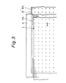
- the suction tables 8 are connected to a vacuum pump or exhaust blower 10 through pipes 9. Referring to Figs. 2 and 3 illustrating the positional relationship and structure of the suction table 8 and mesh belt 4, the suction table 8 is secured to a machine frame (not shown) in close proximity to the lower end of the delivery side of the mesh belt 4.
- suction pipe 9 is connected to the lower or side surface of the suction table 8, which is communicated with the vacuum pump or exhaust blower 10, so that vacuum or subatmospheric pressure is maintained in a hollow chamber 8B.
- Small apertures 4A are formed on the mesh belt 4.
- a mesh screen having a high mesh ratio be used.
- This mesh belt 4 is prepared according to an electroplating method widely adopted at the present for the production of rotary mesh screens. If this method is adopted, a mesh belt of 40 to 200 mesh is ordinarily obtained.
- mesh belts of metals and non- metallic materials may be used.
- a mesh belt prepared according to the above-mentioned electroplating method is preferred because the friction resistance to the suction table 8 is maintained at an appropriate level, small apertures can be formed easily and a completely endless belt can be obtained.
- the substrate 1 since a sucking force is imposed on the entire surface of the substrate 1 by the operation of the vacuum pump or exhaust blower 10, the substrate 1 is delivered in the printing zone P in the state where the substrate 1 adheres closely to the mesh belt 4 and is integrated with the mesh belt 4. If this sucking operation is continued even while the mesh belt 4 is stopped, the substrate 1 is fixed on the mesh belt 4 in the state adhering closely thereto. Accordingly, printing can be perfomred precisely without dislocation or elongation or contraction.
- a plurality of planographic printing units 11 are arranged at intervals corresponding to the feed repeat, and if necessary, intermediate driers 12 are arranged in intermediate portions between adjacent printing units 11, whereby printing and drying are effected for respective colors.
- the second characteristic feature of the present invention is that marks for respective feeds of the substrate 1 are printed on the substrate 1 before printing of a first color and at the subsequent printing operation, the marks for respective-feeds are detected to control the feed lengths of the mesh belt 4.
- a marking device 20 is arranged to print marks for respective feeds of the substrate 1 before printing of a first color.
- This marking device 20 comprises, for example, a stamping device or small screen printing device, and marks are printed on the margin of the substrate 1. It is sufficient if the size of the marks is such that the marks can be detected by a photoelectric sensor. If the substrate 1 is a white paper, a black or brown ink may be used for printing the marks.
- Detection mechanisms 21 and 22 for detecting the marks are arranged forwardly of the first printing zone A.
- the detecting mechanism comprises, for example, a photoelectric sensor for detecting marks by relection of light. It is preferred that a pair of a detecting sensor 21 for emitting a deceleration signal and a detecting sensor 22 for emitting a stop signal be arranged forwardly and backwardly,respectively, with respect to the movement of the mesh belt 4.
- the driving motor 5 when the mark printed on the substrate 1 is detected by the detecting sensor 21 for emitting a deceleration signal, the driving motor 5 is decelerated, and when the mark is detected by the detecting sensor 22 for emitting a stop signal, the driving motor 5 is stopped, whereby intermittent driving of the mesh belt 4 is accomplished.
- the detection mechanisms 21 and 22 are arranged so that the positions of the detection mechanisms 21 and 22 can be changed and adjusted in the advancing direction of the belt 4 according to the feed length (repeat length) of the belt 4.
- the distance L between the marking position of the marking device 20 and the detection mechanism corresponds to the intermittent feed length of the belt 4.
- the substrate is intermittently driven integrally with the mesh belt 4 by the above-mentioned sucking action and driving mechanism, and after printing of necessary colors, the substrate 1 is separated from the mesh belt 4, passed through a final drier 13 and introduced into a winding or other step.
- a plurality of suction tables 8 are arranged in a divided manner.
- one suction table may be arranged so that a sucking effect is produced throughout the printing zone from before the initiation of the printing operation to the termination of the printing operation to prevent elongation or contraction or slipping of the substrate 1.
- Fig. 4 illustrates an embodiment of planographic screen printing where the feed repeat is large or the number of colors is large and a long printing zone is necessary.
- the mesh belt 4 is prepared by the electroplating method as in the above-mentioned embodiment, but the circumferential length of the mesh belt is naturally limited for obtaining a completely endless belt, and if the repeat length is large or the color number is large, the length of the mesh belt is insufficient in some cases. Accordingly, there may be adopted a method in which as shown in Fig. 4, the mesh belt 4 and the driving device therefor are divided, and the respective fragments are connected to one another so that they may be driven integrally.
- the mesh belt 4, driving pulleys, driven pulleys and suction tables are constructed and arranged in the same manner as in the embodiment shown in Fig. 1.
- the driving force of the driving motor 5 is divided for respective fragments and transmitted to the respective driving pulleys 2 through reduction gears 17 such as worm gears and the driving pulleys 2 are synchronously driven through line shafts 18.
- an endless mesh belt of a metal is used as a delivering member, and a substrate to be printed is always sucked continuously during either driving or stoppage by a sucking force of a suction table stationarily arranged below the lower surface of the metal mesh belt and is delivered in the state adhering closely to the mesh belt, while the substrate is located at a predetermined position precisely at the time of stoppage.
- intermittent feeding of the mesh belt is controlled by detecting marks printed on the substrate, intermittent feeding is accomplished at a high precision.
- a high feeding precision can be maintained irrespectively of the elasticity of a substrate and printing can be performed smoothly at a high matching precision irrespectively of the kind of a material of the substrate to be printed.
- elongation or contraction of the substrate or minute displacement of the substrate is prevented through the entire length of the printing zone, and the substrate is completely integrated with the mesh belt as the delivery member. Accordingly, the structure of tension adjusting means arranged in the portions for rolling out and up the substrate can be simplified.
Landscapes
- Engineering & Computer Science (AREA)
- Mechanical Engineering (AREA)
- Screen Printers (AREA)
- Delivering By Means Of Belts And Rollers (AREA)
- Advancing Webs (AREA)
- Belt Conveyors (AREA)
- Inking, Control Or Cleaning Of Printing Machines (AREA)
Abstract
Description
- The present invention relates to a continuous multicolor printing method and apparatus. More particularly, the invention relates to a continuous multicolor printing method and apparatus in which a substrate to be printed is delivered into a printing zone by utilizing a suction pressure and is then printed.
- Various printing apparatuses such as gravure printing and rotary offset printing apparatuses have been used as means for continuous multicolor printing of long substrates such as paper, films and metal foils.
- In the screen printing method using a stencil, there is not an appropriate method for delivering a substrate so as to maintain a high matching precision, and as means for performing multicolor printing by the screen printing method, there have been adopted a process in which a long substrate is cut into sheets and a printing plate is exchanged for every color, and a process in which a substrate is intermittently pulled in a rear part of a printing zone and printing is conducted in a continuous manner.
- The former process is defective in that the productivity is naturally low and it is impossible to continuously print a long substrate. In the latter process, since a tension is imposed on the substrate, the substrate is elongated and contracted, and hence, the kind of the substrate is limited for attaining precise printing. Moreover, large and complicated equipment and control are necessary for maintaining the feed tension of the substrate at a constant level.
- As another means for the continuous multicolor screen printing, there can be mentioned an automatic screen printing machine for printing fibrous articles. In this printing machine, an endless belt is used for the delivery of a substrate, and the substrate is bondei to the endless belt through an appropriate adhesive to integrate the substrate completely with the endless belt and intermittent driving of a certain feed rate is given to the integrated assembly. Therefore, a high matching precision can be maintained in this printing process. However, in the case where the substrate is a paper or film, peeling of the substrate from the endless belt is very difficult or impossible though bonding is possible, and the delivery method using a belt cannot be adopted.
- It is therefore a primary object of the present invention to provide a continuous multicolor screen printing method and apparatus in which even a substrate which cannot be delivered in the state bonded to an endless belt can be printed at a very high printing precision by adopting delivery means similar to those adopted in an automatic screen printing machine without bonding the substrate to an endless belt or the like.
- More specifically, in accordance with one fundamental aspect of the present invention, there is provided a continuous multicolor printing method comprising intermittently driving an endless belt spread between a pair of pulleys by at least one of said pulleys to intermittently feed a substrate to be printed, which is placed on the belt, into a printing zone and printing the substrate through a flat screen, wherein many small apertures are formed in the endless belt, a subatmospheric pressure is produced below the endless belt to intermittently feed the substrate into the printing zone in the state where the substrate adheres closely to the endless belt, marks for respective feeds are printed on the substrate before printing of a first color, and the intermittent feeding of the endless belt is controlled by detecting said marks.
- In accordance with another fundamental aspect of the present invention, there is provided a continuous multicolor printing apparatus comprising an endless belt spread by a pair of pulleys to pass through a printing zone, a driving mechanism for intermittently driving at least one of said pulleys to intermittently feed the endless belt and a printing unit provided with a flat screen arranged in the printing zone, wherein a mesh belt is used as the endless belt, a suction table connected to suction means is arranged below a delivery area of the mesh belt, a substrate to be printed is delivered to the printing zone integrally with the mesh belt by a sucking force, marking means for forming marks on the substrate and detecting means for detecting said marks are arranged forwardly of the printing unit with respect to the moving direction of the mesh belt, and the driving mechanism is decelerated or stopped by a detection signal from said mark detecting means to control the intermittent feeding of the mesh melt.
-
- Fig. 1 is a diagram illustrating a printing apparatus according to one embodiment of the present invention.
- Figs. 2 and 3 are diagrams illustrating an arrangement and structure of a mesh belt and suction table in the present invention.
- Fig. 4 is a aiagram illustrating a printing apparatus according to another embodiment of the present invention.
- The present invention will now be described in detail with reference to embodiments illustrated in the accompanying drawings.
- Referring to Fig. 1 illustrating an embodiment of the continuous multicolor printing apparatus of the present invention, a
driving pulley 2 and a drivenpulley 3 are arranged on the rear and front sides, respectively, in the advancing direction of a substrate 1 to be printed in parallel to each other, and anendless mesh belt 4 of a metal is wound on thepulleys - Intermittent rotation is given to the
driving pulley 2 by a drivingmotor 5 through aworm 6 and aworm gear 7, and corresponding intermittent feeding is given to themesh belt 4. - One of important features of the present invention is that the substrate 1 is delivered to a printing zone P by using the
mesh belt 4 and suction tables 8 are arranged below themesh belt 4 on the delivery side (the upper portion in the drawings). The suction tables 8 are connected to a vacuum pump orexhaust blower 10 throughpipes 9. Referring to Figs. 2 and 3 illustrating the positional relationship and structure of the suction table 8 andmesh belt 4, the suction table 8 is secured to a machine frame (not shown) in close proximity to the lower end of the delivery side of themesh belt 4. - Many
small apertures 8A are formed on the top surface of the suction table 8 substantially uniformly on the entire surface, and thesuction pipe 9 is connected to the lower or side surface of the suction table 8, which is communicated with the vacuum pump orexhaust blower 10, so that vacuum or subatmospheric pressure is maintained in ahollow chamber 8B. - When the vacuum pump or
exhaust blower 10 is actuated for delivering the substrate 1 on themesh belt 4, vacuum or subatmospheric pressure is produced in thehollow chamber 8B of thesuction talbe 8. Accordingly, the substrate 1 is caused to adhere closely to themesh belt 4 and the substrate 1 is smoothly delivered to the printing zone without dislocation or other trouble. -
Small apertures 4A are formed on themesh belt 4. In order to attain a sucking effect on the entire surface of the substrate 1 to be delivered and impart a good smoothness to the printed surface, it is preferred that a mesh screen having a high mesh ratio be used. - This
mesh belt 4 is prepared according to an electroplating method widely adopted at the present for the production of rotary mesh screens. If this method is adopted, a mesh belt of 40 to 200 mesh is ordinarily obtained. - Moreover, various mesh belts of metals and non- metallic materials may be used. However, from the practical viewpoint, a mesh belt prepared according to the above-mentioned electroplating method is preferred because the friction resistance to the suction table 8 is maintained at an appropriate level, small apertures can be formed easily and a completely endless belt can be obtained.
- Referring to Fig. 1 again, in the present invention, since a sucking force is imposed on the entire surface of the substrate 1 by the operation of the vacuum pump or
exhaust blower 10, the substrate 1 is delivered in the printing zone P in the state where the substrate 1 adheres closely to themesh belt 4 and is integrated with themesh belt 4. If this sucking operation is continued even while themesh belt 4 is stopped, the substrate 1 is fixed on themesh belt 4 in the state adhering closely thereto. Accordingly, printing can be perfomred precisely without dislocation or elongation or contraction. - In the embodiment illustrated in Fig. 1, a plurality of
planographic printing units 11 are arranged at intervals corresponding to the feed repeat, and if necessary,intermediate driers 12 are arranged in intermediate portions betweenadjacent printing units 11, whereby printing and drying are effected for respective colors. - The second characteristic feature of the present invention is that marks for respective feeds of the substrate 1 are printed on the substrate 1 before printing of a first color and at the subsequent printing operation, the marks for respective-feeds are detected to control the feed lengths of the
mesh belt 4. - A
marking device 20 is arranged to print marks for respective feeds of the substrate 1 before printing of a first color. Thismarking device 20 comprises, for example, a stamping device or small screen printing device, and marks are printed on the margin of the substrate 1. It is sufficient if the size of the marks is such that the marks can be detected by a photoelectric sensor. If the substrate 1 is a white paper, a black or brown ink may be used for printing the marks. -
Detection mechanisms sensor 21 for emitting a deceleration signal and a detectingsensor 22 for emitting a stop signal be arranged forwardly and backwardly,respectively, with respect to the movement of themesh belt 4. - More specifically, when the mark printed on the substrate 1 is detected by the detecting
sensor 21 for emitting a deceleration signal, thedriving motor 5 is decelerated, and when the mark is detected by the detectingsensor 22 for emitting a stop signal, thedriving motor 5 is stopped, whereby intermittent driving of themesh belt 4 is accomplished. - The
detection mechanisms detection mechanisms belt 4 according to the feed length (repeat length) of thebelt 4. - In other words, the distance L between the marking position of the
marking device 20 and the detection mechanism corresponds to the intermittent feed length of thebelt 4. - The substrate is intermittently driven integrally with the
mesh belt 4 by the above-mentioned sucking action and driving mechanism, and after printing of necessary colors, the substrate 1 is separated from themesh belt 4, passed through afinal drier 13 and introduced into a winding or other step. - In the embodiment illustrated in Fig. 1, a plurality of suction tables 8 are arranged in a divided manner. Of course, in the present invention, one suction table may be arranged so that a sucking effect is produced throughout the printing zone from before the initiation of the printing operation to the termination of the printing operation to prevent elongation or contraction or slipping of the substrate 1.
- Fig. 4 illustrates an embodiment of planographic screen printing where the feed repeat is large or the number of colors is large and a long printing zone is necessary. The
mesh belt 4 is prepared by the electroplating method as in the above-mentioned embodiment, but the circumferential length of the mesh belt is naturally limited for obtaining a completely endless belt, and if the repeat length is large or the color number is large, the length of the mesh belt is insufficient in some cases. Accordingly, there may be adopted a method in which as shown in Fig. 4, themesh belt 4 and the driving device therefor are divided, and the respective fragments are connected to one another so that they may be driven integrally. - In this embodiment, the
mesh belt 4, driving pulleys, driven pulleys and suction tables are constructed and arranged in the same manner as in the embodiment shown in Fig. 1. However, the driving force of the drivingmotor 5 is divided for respective fragments and transmitted to therespective driving pulleys 2 throughreduction gears 17 such as worm gears and thedriving pulleys 2 are synchronously driven throughline shafts 18. - As is apparent from the foregoing description, according to the present invention, an endless mesh belt of a metal is used as a delivering member, and a substrate to be printed is always sucked continuously during either driving or stoppage by a sucking force of a suction table stationarily arranged below the lower surface of the metal mesh belt and is delivered in the state adhering closely to the mesh belt, while the substrate is located at a predetermined position precisely at the time of stoppage.
- Moreover, in the present invention, since intermittent feeding of the mesh belt is controlled by detecting marks printed on the substrate, intermittent feeding is accomplished at a high precision.
- Therefore, according to the present invention, a high feeding precision can be maintained irrespectively of the elasticity of a substrate and printing can be performed smoothly at a high matching precision irrespectively of the kind of a material of the substrate to be printed. Moreover, elongation or contraction of the substrate or minute displacement of the substrate is prevented through the entire length of the printing zone, and the substrate is completely integrated with the mesh belt as the delivery member. Accordingly, the structure of tension adjusting means arranged in the portions for rolling out and up the substrate can be simplified. Thus, prominent advantages can be attained according to the present invention.
Claims (10)
Applications Claiming Priority (2)
| Application Number | Priority Date | Filing Date | Title |
|---|---|---|---|
| JP11281283A JPS606463A (en) | 1983-06-24 | 1983-06-24 | Continuous multi-color printing method and apparatus |
| JP112812/83 | 1983-06-24 |
Publications (2)
| Publication Number | Publication Date |
|---|---|
| EP0130751A2 true EP0130751A2 (en) | 1985-01-09 |
| EP0130751A3 EP0130751A3 (en) | 1985-12-18 |
Family
ID=14596146
Family Applications (1)
| Application Number | Title | Priority Date | Filing Date |
|---|---|---|---|
| EP84304237A Withdrawn EP0130751A3 (en) | 1983-06-24 | 1984-06-22 | Continuous multicolor printing method and apparatus |
Country Status (2)
| Country | Link |
|---|---|
| EP (1) | EP0130751A3 (en) |
| JP (1) | JPS606463A (en) |
Cited By (7)
| Publication number | Priority date | Publication date | Assignee | Title |
|---|---|---|---|---|
| FR2613282A1 (en) * | 1987-04-02 | 1988-10-07 | Svecia Silkscreen Maskiner Ab | SILK-SCREEN PRINTING DEVICE FOR APPLYING MULTI-COLOR FIGURES INTO AN ORDER GIVEN ON PRINTING MATERIAL SO AS TO OBTAIN MULTI-COLOR PRINTED FIGURE THEREFROM |
| EP0309023A3 (en) * | 1987-09-25 | 1990-04-11 | Officine Meccaniche Salvade' S.A.S. | Device for guiding and regulating the forward step in operating machines with intermittent forward motion, particularly automatic screen printing machines |
| ES2049143A2 (en) * | 1991-11-04 | 1994-04-01 | Cremades Martinez | Continuous multiprinting machine |
| US6053101A (en) * | 1998-04-30 | 2000-04-25 | Hix; Clifford A. | Transfer printing press |
| CN108466476A (en) * | 2018-05-25 | 2018-08-31 | 常州工程职业技术学院 | Stamp positioning device for woollen blanket fabric |
| ES2750073A1 (en) * | 2018-09-24 | 2020-03-24 | Asitec Ceram S L | SUPPORT BASE FOR CONVEYOR BELTS IN CONTINUOUS DIGITAL PRINTING MACHINES (Machine-translation by Google Translate, not legally binding) |
| US11314160B2 (en) * | 2020-01-07 | 2022-04-26 | Wenzhou Wapro Technology Co., Ltd. | X-ray film packaging bag printer |
Families Citing this family (4)
| Publication number | Priority date | Publication date | Assignee | Title |
|---|---|---|---|---|
| JPS62174150A (en) * | 1986-01-29 | 1987-07-30 | Teijin Ltd | Roll-to-roll type screen printer |
| JPS63315239A (en) * | 1987-06-18 | 1988-12-22 | Yokohama T-Pu Kogyo Kk | Continuous screen printing method and its printing device |
| HK1080040B (en) * | 2002-10-30 | 2010-08-06 | Lifescan Scotland Ltd | Enzyme print humidification in a continuous process for manufacture of electrochemical sensors |
| CN109367208B (en) * | 2018-10-25 | 2020-12-04 | 合肥艾特标牌有限公司 | Production line of silk-screen label |
Family Cites Families (6)
| Publication number | Priority date | Publication date | Assignee | Title |
|---|---|---|---|---|
| DE1228277B (en) * | 1963-03-28 | 1966-11-10 | Zimmer Johannes | Device for holding a flat material |
| US3848528A (en) * | 1972-09-25 | 1974-11-19 | Moffitt R Co | Multi-station printing system |
| CH565654A5 (en) * | 1973-07-11 | 1975-08-29 | Precision Screen Machines | Continuous pattern printing on screen printing press - with simultaneous drying facilities |
| US4273042A (en) * | 1977-11-26 | 1981-06-16 | Toshin Kogyo Co., Ltd. | Automatic screen printing process and apparatus |
| JPS6034468B2 (en) * | 1978-10-07 | 1985-08-08 | 東伸工業株式会社 | Automatic screen printing equipment |
| DE2812220A1 (en) * | 1978-03-20 | 1979-09-27 | Brueckner Apparatebau Gmbh | METHOD AND DEVICE FOR PRINTING A TRAIL TRANSPORTED IN PARAGRAPH |
-
1983
- 1983-06-24 JP JP11281283A patent/JPS606463A/en active Pending
-
1984
- 1984-06-22 EP EP84304237A patent/EP0130751A3/en not_active Withdrawn
Cited By (9)
| Publication number | Priority date | Publication date | Assignee | Title |
|---|---|---|---|---|
| FR2613282A1 (en) * | 1987-04-02 | 1988-10-07 | Svecia Silkscreen Maskiner Ab | SILK-SCREEN PRINTING DEVICE FOR APPLYING MULTI-COLOR FIGURES INTO AN ORDER GIVEN ON PRINTING MATERIAL SO AS TO OBTAIN MULTI-COLOR PRINTED FIGURE THEREFROM |
| EP0309023A3 (en) * | 1987-09-25 | 1990-04-11 | Officine Meccaniche Salvade' S.A.S. | Device for guiding and regulating the forward step in operating machines with intermittent forward motion, particularly automatic screen printing machines |
| ES2049143A2 (en) * | 1991-11-04 | 1994-04-01 | Cremades Martinez | Continuous multiprinting machine |
| GB2290502A (en) * | 1991-11-04 | 1996-01-03 | Martonez Francisco Cremades | Continuous multiprinting machine |
| US6053101A (en) * | 1998-04-30 | 2000-04-25 | Hix; Clifford A. | Transfer printing press |
| CN108466476A (en) * | 2018-05-25 | 2018-08-31 | 常州工程职业技术学院 | Stamp positioning device for woollen blanket fabric |
| ES2750073A1 (en) * | 2018-09-24 | 2020-03-24 | Asitec Ceram S L | SUPPORT BASE FOR CONVEYOR BELTS IN CONTINUOUS DIGITAL PRINTING MACHINES (Machine-translation by Google Translate, not legally binding) |
| US11314160B2 (en) * | 2020-01-07 | 2022-04-26 | Wenzhou Wapro Technology Co., Ltd. | X-ray film packaging bag printer |
| DE102020129304B4 (en) | 2020-01-07 | 2023-11-30 | Wenzhou Wapro Technology Co., Ltd. | Printer for printing x-ray film packaging bags |
Also Published As
| Publication number | Publication date |
|---|---|
| EP0130751A3 (en) | 1985-12-18 |
| JPS606463A (en) | 1985-01-14 |
Similar Documents
| Publication | Publication Date | Title |
|---|---|---|
| JP4219982B2 (en) | Equipment for transporting sheet materials | |
| EP0130751A2 (en) | Continuous multicolor printing method and apparatus | |
| DE102008042194B4 (en) | Method and apparatus for performing transfer printing on a printed paper sheet | |
| US5447486A (en) | Maintaining perforation phasing | |
| US4334672A (en) | Apparatus for automatically applying sheet units to endless web | |
| GB2289665A (en) | Labels and manufacture thereof | |
| EP0672525B1 (en) | Apparatus for printing proofs | |
| US6112651A (en) | Foil-stamping machine that can accept stamping cylinders of different diameters | |
| US20040173113A1 (en) | Quality control device | |
| US3147006A (en) | Method and apparatus for printing and/or processing webs of material | |
| US4190478A (en) | Process and apparatus for production of faced or laminated sheets | |
| US8651161B2 (en) | Sheet-fed offset printing press | |
| JP2026034696A (en) | Transfer device | |
| US20110108197A1 (en) | Sheet overlap device | |
| JPH0366151B2 (en) | ||
| EP0102743A2 (en) | Method and apparatus for conveying substrate in continuous multicolor printing press | |
| GB1444693A (en) | Web printing method and machine | |
| EP0778130B1 (en) | Apparatus for printing on a circular section container | |
| US4706863A (en) | Intermittent feeding apparatus for a continuous sheet | |
| JPS6093055A (en) | Intermittent feed device for base material | |
| JPS6056552A (en) | Conveying apparatus of substrate in automatic screen printing machine | |
| GB2145663A (en) | Method and apparatus for regulating printing in printing machines | |
| JP2836933B2 (en) | Paper feed timing correction device | |
| US20110048646A1 (en) | Sheet overlap device | |
| JP3183336B2 (en) | Feed control method for resin sheet with printed pattern |
Legal Events
| Date | Code | Title | Description |
|---|---|---|---|
| PUAI | Public reference made under article 153(3) epc to a published international application that has entered the european phase |
Free format text: ORIGINAL CODE: 0009012 |
|
| AK | Designated contracting states |
Designated state(s): CH DE FR GB IT LI NL SE |
|
| PUAL | Search report despatched |
Free format text: ORIGINAL CODE: 0009013 |
|
| AK | Designated contracting states |
Designated state(s): CH DE FR GB IT LI NL SE |
|
| 17P | Request for examination filed |
Effective date: 19860612 |
|
| 17Q | First examination report despatched |
Effective date: 19871107 |
|
| STAA | Information on the status of an ep patent application or granted ep patent |
Free format text: STATUS: THE APPLICATION IS DEEMED TO BE WITHDRAWN |
|
| 18D | Application deemed to be withdrawn |
Effective date: 19880323 |
|
| RIN1 | Information on inventor provided before grant (corrected) |
Inventor name: ICHINOSE, SHIRO Inventor name: YAMASAKI, AKIO |