EP0130901A1 - Messkopf für ein Magnetfeldgradientenvektormessgerät, Messgerät mit einem solchen Kopf und Verfahren zum Messen - Google Patents
Messkopf für ein Magnetfeldgradientenvektormessgerät, Messgerät mit einem solchen Kopf und Verfahren zum Messen Download PDFInfo
- Publication number
- EP0130901A1 EP0130901A1 EP84401335A EP84401335A EP0130901A1 EP 0130901 A1 EP0130901 A1 EP 0130901A1 EP 84401335 A EP84401335 A EP 84401335A EP 84401335 A EP84401335 A EP 84401335A EP 0130901 A1 EP0130901 A1 EP 0130901A1
- Authority
- EP
- European Patent Office
- Prior art keywords
- measuring
- magnetic field
- cell
- magnetic
- compensation
- Prior art date
- Legal status (The legal status is an assumption and is not a legal conclusion. Google has not performed a legal analysis and makes no representation as to the accuracy of the status listed.)
- Granted
Links
- 238000000034 method Methods 0.000 title claims abstract description 8
- 238000005259 measurement Methods 0.000 claims abstract description 58
- 230000010287 polarization Effects 0.000 claims abstract description 17
- 230000000694 effects Effects 0.000 claims abstract description 9
- 239000000696 magnetic material Substances 0.000 claims abstract description 3
- 238000004804 winding Methods 0.000 claims description 27
- 230000001939 inductive effect Effects 0.000 claims description 9
- 230000033228 biological regulation Effects 0.000 claims description 4
- 239000004065 semiconductor Substances 0.000 claims description 2
- 230000004069 differentiation Effects 0.000 claims 2
- 230000001902 propagating effect Effects 0.000 claims 1
- 238000001514 detection method Methods 0.000 description 6
- 230000005284 excitation Effects 0.000 description 5
- 238000010586 diagram Methods 0.000 description 4
- 238000004519 manufacturing process Methods 0.000 description 2
- 238000000691 measurement method Methods 0.000 description 2
- 230000035945 sensitivity Effects 0.000 description 2
- 229910052688 Gadolinium Inorganic materials 0.000 description 1
- GYHNNYVSQQEPJS-UHFFFAOYSA-N Gallium Chemical compound [Ga] GYHNNYVSQQEPJS-UHFFFAOYSA-N 0.000 description 1
- 230000005540 biological transmission Effects 0.000 description 1
- 238000006243 chemical reaction Methods 0.000 description 1
- 238000000407 epitaxy Methods 0.000 description 1
- UIWYJDYFSGRHKR-UHFFFAOYSA-N gadolinium atom Chemical compound [Gd] UIWYJDYFSGRHKR-UHFFFAOYSA-N 0.000 description 1
- 229910052733 gallium Inorganic materials 0.000 description 1
- 239000002223 garnet Substances 0.000 description 1
- 238000012886 linear function Methods 0.000 description 1
- 230000005415 magnetization Effects 0.000 description 1
- 239000000203 mixture Substances 0.000 description 1
- 230000003287 optical effect Effects 0.000 description 1
- 230000008054 signal transmission Effects 0.000 description 1
- 238000001228 spectrum Methods 0.000 description 1
- 230000001960 triggered effect Effects 0.000 description 1
Images


Classifications
-
- G—PHYSICS
- G01—MEASURING; TESTING
- G01R—MEASURING ELECTRIC VARIABLES; MEASURING MAGNETIC VARIABLES
- G01R33/00—Arrangements or instruments for measuring magnetic variables
- G01R33/02—Measuring direction or magnitude of magnetic fields or magnetic flux
- G01R33/022—Measuring gradient
-
- G—PHYSICS
- G01—MEASURING; TESTING
- G01R—MEASURING ELECTRIC VARIABLES; MEASURING MAGNETIC VARIABLES
- G01R33/00—Arrangements or instruments for measuring magnetic variables
- G01R33/02—Measuring direction or magnitude of magnetic fields or magnetic flux
- G01R33/032—Measuring direction or magnitude of magnetic fields or magnetic flux using magneto-optic devices, e.g. Faraday or Cotton-Mouton effect
- G01R33/0322—Measuring direction or magnitude of magnetic fields or magnetic flux using magneto-optic devices, e.g. Faraday or Cotton-Mouton effect using the Faraday or Voigt effect
Definitions
- the present invention relates to magnetic field gradient vector measurement devices. It relates more particularly to a measuring head making it possible to measure the magnetic field gradient vector between two points in space as well as to a magnetic field gradient vector measuring apparatus using such a head.
- Directive magnetometers can also be used, such as the magnetometers described in French patent application No. 79 30721 as well as in the first addition to this patent published under No. 2,517,831.
- two magnetometers could make the gradient measurement provided that their measurement axes are perfectly aligned.
- such an alignment poses implementation problems. These problems are all the more difficult to solve when the fields to be measured are weak.
- the invention makes it possible to solve these production problems as regards the alignment of the measurement axes of these measurement members.
- the subject of the invention is therefore a measuring head for an apparatus for magnetic field gradient vector measurement characterized in that it comprises an emission device making it possible to emit a linearly polarized light beam; first and second cells of magnetic material, each cell having an inlet face and an outlet face aligned along the axis of the light beam and allowing, within it, a guided propagation of the beam as well as a rotation of the direction of polarization of the beam during its propagation; means for measuring polarization rotation associated with each cell along the axis of the light beam, receiving the beam after crossing the associated cell and measuring the polarization rotation of the beam; difference calculating means receiving signals representing the measurement results of the measuring means and providing in exchange information representative of the difference of the two measurements.
- the invention also relates to a magnetic field gradient measurement method as well as an apparatus implementing the measurement head of the invention and the measurement method.
- the measurement head in FIG. 1 comprises a semiconductor laser source or laser diode 1, two polarizers 13 and 14, two measurement cells 2 and 3, two analyzers 4 and 5 and two photodetector diodes 6 and 7 located in a yOz plane .
- the laser diode 1 emits from two of its opposite faces two collimated light beams F1 and F2 whose axes are strictly in line with one another.
- the emissive surface of each face typically has dimensions of 0.2 microns by 15 microns.
- Such a diode is supplied by a determined electrical voltage applied to these input connections E10 and E11.
- the measurement cell 2 comprises a plate 20 cut in a garnet of gadolinium and gallium called GGG whose dimensions length by width and by thickness are approximately 5 ⁇ 3 ⁇ 0.7 mm.
- GGG a garnet of gadolinium and gallium
- YIG a relatively thick layer of YIG was grown by epitaxy corresponding substantially to the composition Gd 0.45 Y 2.55 Ga 0 , 9 Fe 4 , 1 O 12 .
- the thickness obtained can be between 5 and 110 microns and a typical value is 20 microns.
- Such a thickness of YIG makes it possible to propagate the light in a guided but multimode manner, and under these conditions the Faraday effect due to the magnetic field is manifested only by a rotation of the plane of polarization of the light and no longer by a conversion of the mode TM in TE mode. This allows the light beam to be coupled by the end faces of the YIG layer.
- the functional role of the YIG layer will be considered in the use of the wafer 20.
- the measuring cell 2 also includes an excitation winding 23 and a compensation winding 24, both concentric inside which the wafer 20 is placed, as well as two pole pieces 21 and 22 located on either side of the wafer 20 and inducing a continuous magnetic field in the wafer 20 along the main plane of the wafer and transverse to the direction of light propagation in the wafer.
- the measurement cell 3 is constituted identically to that of the measurement cell 2.
- the winding 33 has the same characteristics that the winding 23 to which it is connected in series by the connection wire 19 so that supplied by the same current these two windings induce identical magnetic fields in the two plates 20 and 30. It should be noted that these two windings 23 and 33 could be a single winding encompassing the two plates 20 and 30.
- the two measurement cells 2 and 3 are located on either side of the laser diode on the paths of the beams FI and F2.
- the wafer 20 of the cell 2 receives the beam FI on its input face 25 and retransmits it by its output face 26 to the analyzer 4 and to the photodetector diode 6. It is the same for the wafer 30 of the measurement cell 3 with regard to the beam F2, the analyzer 5 and the photodetector diode 7.
- the laser diode 1 is supplied by its input terminals E10 and E11 using an appropriate source, not shown. It provides an IF light beam with a power of a few milliwatts at a wavelength of 1.3 microns.
- the beam FI is coupled to the wafer 20 by the input face 25.
- the wafer 20 plays the role of waveguide.
- the magnetic field to be measured has the effect of inducing, in the wafer 20, a Faraday effect which is manifested by a rotation of the plane of polarization of the light. This rotation is proportional to the intensity of the component of the magnetic field along the direction of propagation of light, that is to say the axis Oz. It is therefore advantageous to orient the assembly of the measuring head shown in FIG. 1 in the magnetic field to be measured so that the beam FI is directed along the lines of this magnetic field.
- pole pieces 21 and 22 induce in the wafer 20 a magnetic field directed along the axis Oy so that in the absence of a field to be measured, the magnetization vector is transverse and the effect of a field to be measured along the Oz axis is maximum. It should be noted that this transverse field supplied by parts 21 and 22 saturates the plates at a value which can reach the value of 1 oersted.
- the rotation of the plane of polarization due to the field to be measured is detected, after transmission by the face 26 of the plate 20 and crossed by the analyzer 4, by the photodetector diode 6.
- the latter provides at its output S6 a measurement signal to measurement devices not shown.
- the excitation winding 23 is supplied with an alternating current.
- the windings 23 and 33 of cells 2 and 3 are supplied in series by the input connections E20 and E30.
- the winding 23 induces in the wafer 20 an alternating magnetic field parallel to the direction of propagation of the beam FI, that is to say along the axis Oz, and therefore parallel to the field to be measured. This is modulated by the alternating field supplied by the coil 23.
- the intensity of the light detected by the photodetector diode 6 is therefore modulated.
- the intensity of the light varies according to a law containing only even harmonics of the excitation signal applied to the winding 23.
- the presence of a magnetic field to be measured along the Oz axis gives rise to the appearance of odd harmonics.
- the amplitude of the fundamental varies according to the value of the field to be measured.
- the compensation winding 24 is supplied by its input terminals E21 and E22 with direct current by means of supply circuits not shown.
- the coil 24 induces in the wafer 20, a continuous magnetic field in the direction of the beam FI, that is to say in the direction of the field to be measured.
- the measurement cell 2 therefore made it possible to measure a magnetic field.
- the measuring cell 3 works in the same way and also makes it possible to measure a magnetic field.
- the difference of the direct currents supplied to the input terminals 21, 22 of the compensation winding 34 gives the difference of the amplitudes of the magnetic fields measured at locations of the measurement cells 2 and 3. Furthermore, these cells and being oriented along the same axis and along the direction of the field to be measured, the difference in the measured direct currents represents the value of the vector of the magnetic field gradient.
- the measuring head according to the invention therefore makes it possible by placing the measuring cells 2 and 3 on the paths of the light beams emitted by the laser diode 1, and using the property of unidirectionality of the light beams emitted to precisely align the cells of measure 2 and 3, to measure the value of a magnetic field gradient vector.
- FIG. 2 represents a measurement head in which the laser diode 1 is placed on the same side with respect to the measurement cells 2 and 3. These are rigorously aligned in the direction of a beam emitted by the laser diode 1.
- the beam FI emitted by the laser diode 1 is directed onto a photodetector diode 8 which delivers a signal and allows, by means not shown and known, to adjust the power supply and therefore the emission power of the laser diode 1.
- the beam F2 of the laser diode 1 is transmitted to a polarizer 14 which transmits it to the input face 25 of the wafer 29 of the cell 2. The latter retransmits it by the output face 26 in the form of a beam F5 at the input face 35 of the wafer 30 of the cell 3. Finally, the beam F6 coming from the face 36 is transmitted by the analyzer 5 to a photodetector cell 7.
- the operation of the measurement cells 2 and 3 is identical to that of the measurement cells of FIG. 1.
- the inputs E21 and E22 of the winding 24 and the inputs E31 and E32 of the winding 34 are provided with suitable direct currents, the effects of the fields magnetic at the locations of the two measuring cells are compensated.
- the difference in the direct currents supplied makes it possible to obtain the value of the magnetic field gradient.
- the difference of this arrangement compared to that of FIG. 1 lies in the fact that the beam FI and the photodetector diode 8 are used to regulate the emission power of the laser diode 1.
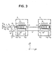
- FIG. 3 represents a measurement head in which the light beam goes back and forth in the measurement cells 2 and 3.
- Cells 2 and 3 are identical in structure to those in Figures 1 and 2.
- a system of prisms 10, 11, 12 has been inserted in the path of the beam F2 between the laser diode 1 and the measurement cell 2, making it possible to return the light to a photodetector diode 7.
- a mirror 9 was placed against the outlet face 36 of the wafer 30 of the cell 3.
- the beam Flet the photodetector diode make it possible to adjust the emission power of the laser diode 1.
- the beam F2 due to its polarization is transmitted by the prisms 10 and 11 to the cell 2 which retransmits it to the cell 3.
- the light beam is reflected by the mirror 9 and crosses again the cell 3 then the cell 2.
- the system of prisms 10, 11, 12 reflects the beam supplied by cell 2 and retransmits it to the photodetector diode 7.
- the light beam therefore crosses each cell twice. It therefore appears that the direct currents to be supplied to the inputs E21, E22 of the compensation winding 24 and E31, E32 of the compensation winding 34 must be of amplitude double that necessary to compensate a single crossing of each cell as in the case of FIG. 2. The difference in the currents supplied is therefore twice that obtained with an assembly of the type in FIG. 2. The measurement accuracy of the magnetic field gradient is therefore improved.
- This measurement head corresponds to the explanatory diagram of FIG. 1. It is quite obvious that measurement heads conforming to the principle diagrams of FIGS. 2 and 3 can have a similar embodiment.
- This measuring head comprises a rigid tube 100 the interior of which is fitted with fixed bases 101, 102, 103, 104 and 105 whose main faces are parallel.
- the bases 101, 103 and 105 are provided with a boss, such as 106, the upper face of which has been carefully machined.
- On the bases 101 and 105 are mounted the photodetector diodes 6 and 7 and on the base 103 is mounted the laser diode 1.
- the height adjustment of these components on the bases is easily adjusted using shims not shown.
- On the bases 102 and 104 are mounted plates 20 and 30 with, for example, shims such as 107 for height adjustment.
- the axial adjustment and immobilization of all these components on their base is done in a known manner using means not shown and, in optimal position, they are aligned on the direction of the light beams emitted by the laser diode 1.
- Between the laser diode 1 and the plates 20 on the one hand and 30 were mounted the polarizers 13 and 14 as well as focusing lenses 15 and 16.
- Between the plates 20 and 30 and the photodetector diodes were mounted the analyzers 4 and 5
- the mounting of the polarizers 13 and 14, the lenses 15 and 16 and the analyzers 4 and 5 inside the tube 100, so that it does not introduce any deviation in the direction of the light beams, is done 'a manner known in the art of manufacturing optical instruments.
- the excitation coils 23 and 33, and the compensation coils 24 and 34 are mounted around the tube 100 so as to be centered in the longitudinal direction on the plates 20 and 30.
- the assembly is fixed on a support frame 108 on which are mounted the pole pieces 21, 31 (as well as 22 and 32 not shown in 1 Figure 4), inducing a continuous magnetic field in the plane of the pads 20 and 30 transversely to the direction of the light beams emitted by the laser diode 1.
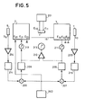
- FIG. 5 represents an exemplary embodiment of the control circuits of the measuring head as described in relation to FIG. 1.
- This figure shows the laser diode 1 with its input terminals E10 and E11, the measurement cells 2 and 3 with their input terminals E20 to E22 and E30 to E32, the photodetector diodes 6 and 7 with their terminals d 'input S6 and S7.
- the input terminals E22, E32 and E30 are grounded.
- the laser diode is supplied with current by a supply circuit 201 connected to its input terminals E10 and Ell.
- a supply circuit 201 connected to its input terminals E10 and Ell.
- a light power of 4 milliwatts is obtained with a supply intensity of 200 milliamps. Such light power allows perfect to operate the device at the desired sensitivity.
- An oscillator 202 supplies a signal at a relatively high frequency fo, 100 KHz for example. This signal is applied to the input terminal E20 of the measurement cell 2 and is retransmitted to the measurement cell 3 by the connection wire 19. An alternating current therefore flows between the input terminals E20 and E30 in the windings. excitation 23 and 33 (see Figure 1). An alternating field is induced in the plates 20 and 30 according to the direction of the beams FI and F2.
- the photodetector diodes 6 and 7 respectively detect the beams FI and F2 and deliver signals on their output S6 and S7. In the absence of a DC component directed in the direction of propagation of the beams, these signals have a frequency 2fo twice the frequency of the oscillator.
- each filter is compared with the signal supplied by the oscillator 202, in a detection circuit (206, 207) which measures both the amplitude of each of them at the frequency of the fundamental and the change phase during zero crossing.
- the detection circuits 206 and 207 do not provide an output signal.
- the signals detected by the photodetector diodes 6 and 7 are deformed compared to the preceding signals.
- the signal at the output of each filter 214, 215 compared to the signal supplied by the oscillator 202 gives rise in the detection circuits 206 and 207 to the emission of a DC error signal corresponding to the detection carried out.
- the error signal supplied by the detection circuit 206 is transmitted to an amplifier 208 which supplies the input E21 of the measurement cell 2 with a DC current corresponding to the error signal.
- a direct current flows in the compensation winding 24 between the input terminals E21 and E22.
- a continuous magnetic field is induced in the wafer 30.
- the error signal supplied by the detection circuit 207 is transmitted to a direct current supply circuit 209 which supplies a direct current to the measuring cell 3 and induces a continuous magnetic field in the wafer 30.
- a differential amplifier 212 is connected to the output of the supply circuits 208 and 209. It supplies at its output, to a measuring device 213, a signal corresponding to the difference in the levels of the continuous signals supplied to the compensation coils 24 and 34.
- the measuring device 213 therefore makes it possible to display the value of the magnetic field gradient measured between the two locations where the measuring cells 2 and 3 are located.
- Measuring devices 210 and 211 are inserted in the continuous signal transmission circuits at the input terminals E21 and E31. They make it possible to measure, if desired, the value of the magnetic fields at the locations of the measurement cells 2 and 3.
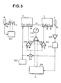
- FIG. 6 represents a circuit diagram making it possible to operate the measuring head of the variants as represented by FIGS. 2 and 3.
- This figure shows the laser diode 1 and its supply circuit 201, the measuring cells 2 and 3 and the photodetector diodes 7 and 8.
- the laser diode is supplied as previously by the supply circuit 201.
- the photodetector diode receiving a light beam from the laser diode supplies a signal at its output S8 and makes it possible to regulate the supply power of the circuit 201.
- Oscillator 202 supplies alternating current between terminals E20 and E30, the two measurement cells 2 and 3.
- the photodetector diode 7 provides on its output S7 a signal which is amplified by the amplifier 205, then filtered by a filter 215.
- the filter 215 provides a signal which is compared with the signal supplied by the oscillator 202 in a circuit comparator 207.
- the comparison circuit 207 provides a continuous error signal which is amplified by two amplifiers 208 and 209 and is applied to the input terminals E21 and E31 of the measurement cells 2 and 3 to supply the compensation windings 24 and 34. These therefore receive the same current which corresponds to maximum compensation.
- the magnetic fields being assumed to be different at the locations of the two measurement cells 2 and 3, it is now necessary to act separately on the supplies of the two compensation coils 23 and 34.
- a regulation circuit 216 is put into operation by means not shown. This start-up can be triggered manually or automatically using a time delay which allows the time necessary for the previous circuits to operate.
- the regulation circuit 216 is of the Proportional-Integral-Derivative type as commonly used in temperature regulation systems for example. It receives the signal supplied by the filter 215, compares it to a reference value to which we will preferably give a zero value. Such a circuit can operate as desired in three different modes providing output signals which are proportional to the result of the comparison, either an integral function or a derived function. It provides in response a control signal on one of the gain control inputs G208 or G209 of the differential amplifiers 208 and 209. One of the differential amplifiers 208 or 209 provides a signal making it possible to complete the compensation.
- a differential amplifier 212 is connected to the gain control inputs G208 and G209. It supplies, on its output, to a measuring device 213, a signal corresponding to the difference of the gain control signals of the amplifiers 208 and 209.
- the measuring device 213 therefore makes it possible to display the value of the magnetic field gradient measured between the two locations where the measuring cells 2 and 3 are located.
Landscapes
- Physics & Mathematics (AREA)
- Engineering & Computer Science (AREA)
- Power Engineering (AREA)
- Condensed Matter Physics & Semiconductors (AREA)
- General Physics & Mathematics (AREA)
- Measuring Magnetic Variables (AREA)
Applications Claiming Priority (2)
| Application Number | Priority Date | Filing Date | Title |
|---|---|---|---|
| FR8311073A FR2548787B1 (fr) | 1983-07-04 | 1983-07-04 | Tete de mesure pour appareil de mesure de vecteur de gradient de champ magnetique, appareil de mesure comprenant une telle tete et procede de mesure |
| FR8311073 | 1983-07-04 |
Publications (2)
| Publication Number | Publication Date |
|---|---|
| EP0130901A1 true EP0130901A1 (de) | 1985-01-09 |
| EP0130901B1 EP0130901B1 (de) | 1987-11-04 |
Family
ID=9290465
Family Applications (1)
| Application Number | Title | Priority Date | Filing Date |
|---|---|---|---|
| EP84401335A Expired EP0130901B1 (de) | 1983-07-04 | 1984-06-26 | Messkopf für ein Magnetfeldgradientenvektormessgerät, Messgerät mit einem solchen Kopf und Verfahren zum Messen |
Country Status (5)
| Country | Link |
|---|---|
| US (1) | US4731581A (de) |
| EP (1) | EP0130901B1 (de) |
| CA (1) | CA1256497A (de) |
| DE (1) | DE3467250D1 (de) |
| FR (1) | FR2548787B1 (de) |
Cited By (3)
| Publication number | Priority date | Publication date | Assignee | Title |
|---|---|---|---|---|
| FR2603705A1 (fr) * | 1986-09-05 | 1988-03-11 | Thomson Csf | Tete de mesure de champ magnetique integree et son procede de realisation |
| WO2009084731A1 (en) * | 2007-12-28 | 2009-07-09 | Canon Kabushiki Kaisha | Atomic magnetometer and magnetic sensing method |
| CN103293493A (zh) * | 2013-05-17 | 2013-09-11 | 中国科学院上海微系统与信息技术研究所 | 基于空间相关性的空间磁场及全张量梯度测量系统及方法 |
Families Citing this family (8)
| Publication number | Priority date | Publication date | Assignee | Title |
|---|---|---|---|---|
| US5115340A (en) * | 1988-09-30 | 1992-05-19 | Amoco Corporation | High average power Faraday isolator |
| US5177805A (en) * | 1991-04-01 | 1993-01-05 | American Research Corp. Of Va. | Optical sensors utilizing multiple reflection |
| US6462856B1 (en) * | 2000-05-31 | 2002-10-08 | Lucent Technologies Inc. | Method and apparatus for modulating an optical signal using polarization |
| JP2004093257A (ja) * | 2002-08-30 | 2004-03-25 | Oki Electric Ind Co Ltd | 光センサユニット |
| KR101810985B1 (ko) * | 2011-09-02 | 2017-12-21 | 삼성전자주식회사 | 자기장을 이용한 단말의 위치 측정 방법 및 장치 |
| US9348000B1 (en) * | 2012-12-20 | 2016-05-24 | Seagate Technology Llc | Magneto optic kerr effect magnetometer for ultra-high anisotropy magnetic measurements |
| US11193990B2 (en) | 2017-04-19 | 2021-12-07 | Texas Instruments Incorporated | Integrated microfabricated alkali vapor cell sensor with reduced heading error |
| CN110498188B (zh) * | 2019-07-08 | 2020-08-28 | 中国矿业大学 | 综采工作面刮板输送机链条状态检测方法 |
Citations (3)
| Publication number | Priority date | Publication date | Assignee | Title |
|---|---|---|---|---|
| US3703682A (en) * | 1968-10-30 | 1972-11-21 | Us Navy | Long axis gradiometer |
| EP0030876A1 (de) * | 1979-12-14 | 1981-06-24 | Thomson-Csf | Messwandler für Magnetometer und seine Verwendung in einem Magnetometer |
| US4327327A (en) * | 1980-06-05 | 1982-04-27 | The Singer Company | All-angle gradient magnetometer |
Family Cites Families (8)
| Publication number | Priority date | Publication date | Assignee | Title |
|---|---|---|---|---|
| US2975360A (en) * | 1956-07-05 | 1961-03-14 | Varian Associates | Magnetoabsorption flux meter and gradiometer |
| FR2355299A1 (fr) * | 1976-06-18 | 1978-01-13 | Thomson Csf | Appareil destine a mesurer un champ magnetique |
| FR2517831A2 (fr) * | 1981-12-04 | 1983-06-10 | Thomson Csf | Tete de mesure pour magnetometre et magnetometre comprenant une telle tete |
| FR2524650A1 (fr) * | 1982-04-06 | 1983-10-07 | Thomson Csf | Magnetometre optique |
| US4587487A (en) * | 1982-11-22 | 1986-05-06 | Gould Inc. | Optical fiber magnetometer for measuring D.C. and low frequency fields |
| FR2552883B1 (fr) * | 1983-10-04 | 1985-11-08 | Thomson Csf | Dispositif pour mesurer le gradient d'un champ magnetique par effet magneto-optique |
| GB2171514B (en) * | 1985-02-23 | 1988-03-09 | Stc Plc | Magnetic gradient detector and method |
| US4675522A (en) * | 1985-10-09 | 1987-06-23 | Spectron Development Laboratories, Inc. | Fiber optic magnetic field sensor |
-
1983
- 1983-07-04 FR FR8311073A patent/FR2548787B1/fr not_active Expired
-
1984
- 1984-06-26 DE DE8484401335T patent/DE3467250D1/de not_active Expired
- 1984-06-26 EP EP84401335A patent/EP0130901B1/de not_active Expired
- 1984-06-29 CA CA000457927A patent/CA1256497A/en not_active Expired
-
1987
- 1987-07-13 US US07/073,331 patent/US4731581A/en not_active Expired - Fee Related
Patent Citations (3)
| Publication number | Priority date | Publication date | Assignee | Title |
|---|---|---|---|---|
| US3703682A (en) * | 1968-10-30 | 1972-11-21 | Us Navy | Long axis gradiometer |
| EP0030876A1 (de) * | 1979-12-14 | 1981-06-24 | Thomson-Csf | Messwandler für Magnetometer und seine Verwendung in einem Magnetometer |
| US4327327A (en) * | 1980-06-05 | 1982-04-27 | The Singer Company | All-angle gradient magnetometer |
Cited By (7)
| Publication number | Priority date | Publication date | Assignee | Title |
|---|---|---|---|---|
| FR2603705A1 (fr) * | 1986-09-05 | 1988-03-11 | Thomson Csf | Tete de mesure de champ magnetique integree et son procede de realisation |
| EP0262016A1 (de) * | 1986-09-05 | 1988-03-30 | Thomson-Csf | Integrierter Magnetfeldmesskopf und Herstellung dafür |
| US4823083A (en) * | 1986-09-05 | 1989-04-18 | Thomson-Csf | Integrated head for the measurement of magnetic fields and method of making this head |
| WO2009084731A1 (en) * | 2007-12-28 | 2009-07-09 | Canon Kabushiki Kaisha | Atomic magnetometer and magnetic sensing method |
| US8405389B2 (en) | 2007-12-28 | 2013-03-26 | Canon Kabushiki Kaisha | Atomic magnetometer and magnetic sensing method |
| CN103293493A (zh) * | 2013-05-17 | 2013-09-11 | 中国科学院上海微系统与信息技术研究所 | 基于空间相关性的空间磁场及全张量梯度测量系统及方法 |
| CN103293493B (zh) * | 2013-05-17 | 2016-01-20 | 中国科学院上海微系统与信息技术研究所 | 基于空间相关性的空间磁场及全张量梯度测量系统及方法 |
Also Published As
| Publication number | Publication date |
|---|---|
| FR2548787B1 (fr) | 1986-01-31 |
| EP0130901B1 (de) | 1987-11-04 |
| FR2548787A1 (fr) | 1985-01-11 |
| US4731581A (en) | 1988-03-15 |
| DE3467250D1 (en) | 1987-12-10 |
| CA1256497A (en) | 1989-06-27 |
Similar Documents
| Publication | Publication Date | Title |
|---|---|---|
| EP0081412B1 (de) | Messkopf für Magnetometer | |
| EP0091351B1 (de) | Optisches Magnetometer | |
| EP0130901B1 (de) | Messkopf für ein Magnetfeldgradientenvektormessgerät, Messgerät mit einem solchen Kopf und Verfahren zum Messen | |
| CN115839929B (zh) | 一种高时空分辨的磁光偏振成像测量系统 | |
| US6833694B2 (en) | Current measurement technique and current measurement apparatus | |
| EP3907513B1 (de) | Stromsensor, der auf dem faraday-effekt in einem atomgas beruht | |
| EP0030876B1 (de) | Messwandler für Magnetometer und seine Verwendung in einem Magnetometer | |
| FR2598518A1 (fr) | Magnetometre a helium pompe par laser | |
| EP0136955B1 (de) | Anordnung zum Messen des Gradienten eines magnetischen Feldes durch magneto-optischen Effekt | |
| EP0579537A1 (de) | Magnetometer mit polarisiertem Licht und gesteuertem Hochfrequenzfeld | |
| EP0262016A1 (de) | Integrierter Magnetfeldmesskopf und Herstellung dafür | |
| EP0151895B1 (de) | Magneto-optisches Magnetfeldmessungsverfahren, Anordnung und Zelle zum Messen mit solch einem Verfahren | |
| JP3167189B2 (ja) | 電圧測定装置 | |
| EP0252813A1 (de) | Vorrichtung zur Hochfrequenzmodulation von polarisiertem Licht | |
| EP0020263B1 (de) | Prüfmaschine für Blasenspeicher und eine solche Maschine verwendendes Prüfverfahren | |
| EP3961236B1 (de) | Elliptisch polarisiertes magnetometer mit zwei hochfrequenz-feldkomponenten zur detektion der parametrischen absorptionsresonanz | |
| CA3074080A1 (fr) | Magnetometre scalaire isotrope et tout optique | |
| FR3088729A1 (fr) | Magnetometre en alignement a decalage angulaire entre polarisations des faisceaux de pompe et de sonde | |
| JP2025076308A (ja) | 電流測定装置および電流測定方法 | |
| FR2668610A1 (fr) | Procede de reglage d'un magnetometre optique. | |
| EP2612158A1 (de) | Vorrichtung und verfahren zur charakterisierung eines laserstrahls | |
| FR2682769A1 (fr) | Magnetometre laser. |
Legal Events
| Date | Code | Title | Description |
|---|---|---|---|
| PUAI | Public reference made under article 153(3) epc to a published international application that has entered the european phase |
Free format text: ORIGINAL CODE: 0009012 |
|
| AK | Designated contracting states |
Designated state(s): DE GB IT |
|
| 17P | Request for examination filed |
Effective date: 19850417 |
|
| 17Q | First examination report despatched |
Effective date: 19860513 |
|
| GRAA | (expected) grant |
Free format text: ORIGINAL CODE: 0009210 |
|
| AK | Designated contracting states |
Kind code of ref document: B1 Designated state(s): DE GB IT |
|
| ITF | It: translation for a ep patent filed | ||
| REF | Corresponds to: |
Ref document number: 3467250 Country of ref document: DE Date of ref document: 19871210 |
|
| GBT | Gb: translation of ep patent filed (gb section 77(6)(a)/1977) | ||
| PLBE | No opposition filed within time limit |
Free format text: ORIGINAL CODE: 0009261 |
|
| STAA | Information on the status of an ep patent application or granted ep patent |
Free format text: STATUS: NO OPPOSITION FILED WITHIN TIME LIMIT |
|
| 26N | No opposition filed | ||
| PGFP | Annual fee paid to national office [announced via postgrant information from national office to epo] |
Ref country code: GB Payment date: 19900518 Year of fee payment: 7 |
|
| PGFP | Annual fee paid to national office [announced via postgrant information from national office to epo] |
Ref country code: DE Payment date: 19900519 Year of fee payment: 7 |
|
| ITTA | It: last paid annual fee | ||
| PG25 | Lapsed in a contracting state [announced via postgrant information from national office to epo] |
Ref country code: GB Effective date: 19910626 |
|
| GBPC | Gb: european patent ceased through non-payment of renewal fee | ||
| PG25 | Lapsed in a contracting state [announced via postgrant information from national office to epo] |
Ref country code: DE Effective date: 19920401 |