EP0130968A1 - Dispositif pour le test d'un moteur à combustion interne - Google Patents
Dispositif pour le test d'un moteur à combustion interne Download PDFInfo
- Publication number
- EP0130968A1 EP0130968A1 EP84890099A EP84890099A EP0130968A1 EP 0130968 A1 EP0130968 A1 EP 0130968A1 EP 84890099 A EP84890099 A EP 84890099A EP 84890099 A EP84890099 A EP 84890099A EP 0130968 A1 EP0130968 A1 EP 0130968A1
- Authority
- EP
- European Patent Office
- Prior art keywords
- measured
- combustion engine
- internal combustion
- laser
- vibration
- Prior art date
- Legal status (The legal status is an assumption and is not a legal conclusion. Google has not performed a legal analysis and makes no representation as to the accuracy of the status listed.)
- Granted
Links
- 238000002485 combustion reaction Methods 0.000 title claims abstract description 48
- 238000012360 testing method Methods 0.000 title claims abstract description 12
- 238000011156 evaluation Methods 0.000 claims abstract description 15
- 230000005855 radiation Effects 0.000 claims abstract description 14
- 238000000034 method Methods 0.000 claims abstract description 6
- 230000008859 change Effects 0.000 claims abstract description 5
- 230000008569 process Effects 0.000 claims abstract description 3
- 238000005259 measurement Methods 0.000 claims description 14
- 230000000694 effects Effects 0.000 abstract description 2
- 238000001514 detection method Methods 0.000 abstract 1
- 210000003128 head Anatomy 0.000 description 6
- 238000011161 development Methods 0.000 description 2
- 238000010586 diagram Methods 0.000 description 2
- 230000010355 oscillation Effects 0.000 description 2
- 206010057430 Retinal injury Diseases 0.000 description 1
- 238000010521 absorption reaction Methods 0.000 description 1
- 230000001419 dependent effect Effects 0.000 description 1
- 238000006073 displacement reaction Methods 0.000 description 1
- 230000002349 favourable effect Effects 0.000 description 1
- 229910052734 helium Inorganic materials 0.000 description 1
- 239000001307 helium Substances 0.000 description 1
- SWQJXJOGLNCZEY-UHFFFAOYSA-N helium atom Chemical compound [He] SWQJXJOGLNCZEY-UHFFFAOYSA-N 0.000 description 1
- 238000007689 inspection Methods 0.000 description 1
- 230000007257 malfunction Effects 0.000 description 1
- 229910052754 neon Inorganic materials 0.000 description 1
- GKAOGPIIYCISHV-UHFFFAOYSA-N neon atom Chemical compound [Ne] GKAOGPIIYCISHV-UHFFFAOYSA-N 0.000 description 1
- 230000003287 optical effect Effects 0.000 description 1
- 210000001747 pupil Anatomy 0.000 description 1
- 230000009467 reduction Effects 0.000 description 1
- 230000004044 response Effects 0.000 description 1
- 239000000725 suspension Substances 0.000 description 1
Images

Classifications
-
- G—PHYSICS
- G01—MEASURING; TESTING
- G01M—TESTING STATIC OR DYNAMIC BALANCE OF MACHINES OR STRUCTURES; TESTING OF STRUCTURES OR APPARATUS, NOT OTHERWISE PROVIDED FOR
- G01M15/00—Testing of engines
- G01M15/04—Testing internal-combustion engines
- G01M15/12—Testing internal-combustion engines by monitoring vibrations
-
- G—PHYSICS
- G01—MEASURING; TESTING
- G01H—MEASUREMENT OF MECHANICAL VIBRATIONS OR ULTRASONIC, SONIC OR INFRASONIC WAVES
- G01H9/00—Measuring mechanical vibrations or ultrasonic, sonic or infrasonic waves by using radiation-sensitive means, e.g. optical means
Definitions
- the invention relates to a device for testing an at least partially fully assembled and externally driven internal combustion engine for the purpose of this test for errors and operating faults expressing a change in the vibration behavior, with a vibration recording device and an associated evaluation unit.
- Known devices of this type usually have simply a receiving device for the internal combustion engine to be tested with the connections required for the external drive, which is arranged in an anechoic chamber or at least largely insulated from ambient noise.
- the internal combustion engine to be tested is assessed by ear by the respective tester - which, of course, also allows only a very rough and subjective check, for example for correctly set valves, the presence of all bearing shells, or the like, because of the very large number of parameters influencing the emitted sound level.
- the object of the present invention is to improve a device of the type mentioned in such a way that the aforementioned disadvantages of the known devices do not occur, and that in particular the testing of an externally driven internal combustion engine for errors or malfunctions expressing itself in a change in the vibration behavior is simple and meaningful in a frequency range of the vibrations that is not limited by the measurement itself. Furthermore, this test should be able to be carried out quickly and without having to carry out any preparatory work on the internal combustion engine, for example in order to permit use in the final inspection of series internal combustion engines.
- the vibration pick-up device for measuring surface vibrations in the vibration pick-up device is known to have at least one laser, the beam of which can be directed onto the locations of the surfaces of the internal combustion engine to be measured, and a receiver for the radiation reflected by the internal combustion engine, and a demodulation device is provided in the evaluation unit, which is made up of that from Measuring point, reflected laser radiation filters out the influence of vibrations of the reflecting surface and processes it further as a measurement signal, and that a control unit cooperating with an adjusting device is provided, which aligns the laser and receiver to the point of the internal combustion engine surface to be measured.
- the recording of vibrations of reflecting surfaces in the direction of an incident laser beam by measuring the reflected beam and comparing its parameters with the corresponding parameters of the incident beam is possible in two basic variants and belongs to the state of the art.
- the first variant is the so-called interference measurement, in which essentially the different phase position of the incident and the reflected beam, or the interference pattern resulting accordingly in a superimposition, are used for the measurement;
- the second variant uses the Doppler effect, that is, by determining the frequency shift of the reflected beam with respect to the impinging beam, which results from the movement of the reflecting surface.
- Methods and electronic devices have become known in particular for the second-mentioned method which allow a very precise vibration analysis which corresponds very well with the actual conditions on the vibrating surface.
- the contactless measurement of surface vibrations at any point on the surface of the internal combustion engine to be tested is possible, which is particularly automatic in connection with the control unit acting on the relative alignment of the laser beam via an adjusting device Examination enables.
- the vibration pick-up device is attached at a relatively arbitrary point in the vicinity of the internal combustion engine, it only being necessary to ensure that all points of interest for the reduction of the surface vibrations are directly accessible to the laser beam and have no excessive inclination towards the incident beam.
- the latter circumstance is significant because - as already indicated - only vibrations in the direction of the incident laser beam can be recorded with such an arrangement, which only allows the component lying in the direction of the incident beam to be determined in the case of an oblique incidence.
- the vibration pick-up device is gimbal-mounted on a measuring slide that can be displaced relative to the surface to be measured, and if adjusting elements are provided on the measuring slide, which are connected to the control unit.
- a measuring slide that can be displaced relative to the surface to be measured
- adjusting elements are provided on the measuring slide, which are connected to the control unit.
- both the laser and the receiver can be arranged fixed relative to the surface to be measured, deflection devices being arranged in the beam path of the emitted as well as the reflected radiation can be pivoted via adjusting devices connected to the control device. Since the lasers which can preferably be used for the purposes of the present invention are relatively large and correspondingly heavy, this configuration, which requires the adjustment of only a few deflecting devices - such as mirrors, prisms or the like - which is easier, faster and more precise to achieve than pivoting the entire vibration pickup device, some advantages.
- the length of the beam path, at different distances between the laser or receiver and the surface to be measured for the different locations of the surface of the internal combustion engine to be measured can be adjusted by means of compensation elements arranged in the beam path, the compensation elements can be actuated via actuators connected to the control unit. Since the exit optics of the laser or the optics to be penetrated by the reflected beam to the receiver - these do not necessarily have to be identical - must be set to a certain distance from the reflecting surface within relatively narrow limits (e.g.
- a distance measuring device known per se which uses the emitted and the received laser beam, is provided for the distance to be covered up to the surface to be measured, which has a servo device for adjusting a lens for the laser beam in ver bond stands.
- a measuring head which is gimbally movably mounted on a measuring slide which is displaceable relative to the surface to be measured, adjusting elements being provided on this measuring slide, which are connected to the control unit and the measuring head being connected via at least one flexible light guide communicates with the fixed laser and receiver.
- the measuring head having the exit opening for the supplied laser beam and the entry opening for the reflected beam need be arranged on the displaceable and gimbal-movable measuring slide, whereby the relatively large-volume and sensitive vibration pick-up device in turn is stationary at a relatively arbitrary point in the vicinity of the test object
- Internal combustion engine can be arranged.
- compensation for the various distances from the point to be measured on the internal combustion engine is also superfluous, provided the distance between the measuring head and the measuring points is the same.
- the beam path can be covered up to just above the surface to be measured, which increases safety, for example for the operating personnel.
- the lasers usually used for such applications only have a power in the range of a few milliwatts and are harmless to humans, retinal damage could occur when the laser beam enters the pupil of the eye directly, which is certainly avoided by the aforementioned cover.
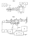
- FIG. 1 shows a device for testing an internal combustion engine 1 for errors or operating faults expressing itself in a change in the vibration behavior, the internal combustion engine 1 being externally driven for the purpose of this test via a drive 2, for example a suitable electric motor.
- a drive 2 for example a suitable electric motor.
- 3 with a control or operating unit is designated, which is connected to the drive 2 and the internal combustion engine 1 and controls or monitors them.
- a vibration pickup device 6 is arranged on an adjusting device 7 for measuring surface vibrations on the internal combustion engine, said adjustment device cooperating with a control unit 8.
- the vibration recording device 6 has a laser 9, the beam 10 of which is measured at the points to be measured the surface of the internal combustion engine 1 can be directed. Furthermore, a receiver (not shown in more detail in FIG. 1) for the radiation reflected by the internal combustion engine is provided in the vibration recording device. Via a supply and evaluation line 11, the vibration pickup device 6 or the adjusting device 7 is connected to the control unit 8, which is coupled to an evaluation unit 12 in the exemplary embodiment shown.
- the evaluation unit 12 has a demodulation device, not shown here, by means of which the influence of vibrations of the reflecting surface is filtered out from the laser radiation reflected from the point to be measured and is further processed as a measurement signal.
- the control unit 8 or the adjusting device 7 serve to align the laser 9 and the receiver for the reflected radiation to the point on the surface of the internal combustion engine 1 to be measured.
- the vibration pick-up device (6 in FIG. 1) shown in more detail in FIG. 2 essentially has a laser 9, the beam of which can be directed at a point 16 of the surface of the internal combustion engine 1 which is not shown here in the direction of arrow 17, as well as one receiver each 18 for the emitted radiation as well as for the radiation reflected from the surface to be measured.
- 19 denotes a so-called Bragg cell, which modulates a frequency f B on the emitted laser beam which has already been split or deflected via prisms 20, 21 and which in terms of structure and function belongs to the prior art.
- optics 23 are also provided, which can be adjusted in a manner not shown here - for example via the control unit 8 in FIG. 1 - to the given distance up to the point 16 on the surface to be measured.
- the function of the device shown is based in principle on the evaluation of the Doppler frequency shift when the emitted laser beam is reflected on a moving surface.
- the frequency of displacement is directly proportional to the time course of the oscillation velocity of the surface to be measured.
- the measurement of the frequency or the frequency profile of the reflected laser light would already be sufficient, since the influence of the vibrating surface could be determined directly by comparison with the known frequency of the emitted light.
- this theoretical possibility cannot be practically implemented with the electronic components known today because of the high frequencies of the emitted light.
- Part of the beam emitted by the laser 9 is therefore modulated in the Bragg cell 19 at a frequency f B of, for example, 40 MHz; Likewise, the received frequency is subsequently changed electronically by a value f S to enable an optimal evaluation of the resulting Doppler signal f D (t) shifted.
- the frequency tracker 26, which is ultimately used to measure the frequency or determine the frequency response, can work in an electronically more favorable lower frequency range due to the shift by f S and only has to be adjusted in its corner frequencies to the maximum occurring Doppler shift corresponding to the greatest vibration velocity to be measured .
- the determined instantaneous frequency is then converted in converter 27 into a signal proportional to the oscillation speed at point 16 of internal combustion engine 1 and output as an analog voltage profile V M (t). This signal corresponds to the analog signal of a conventional mechanical accelerometer after it has been processed by an integrating charge amplifier.
- the control oscilloscope 28 is only used for optical adjustment and control of the Doppler signal.
- f L the original frequency of the laser 9 is designated;
- fU and f 0 (FIG. 3) characterize the mentioned corner frequencies of the frequency tracker 26.
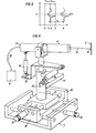
- FIG. 4 shows the displaceable mounting and gimbal suspension of a vibration absorbing device 6, which can be constructed, for example, as shown in FIG. 2.
- the vibration absorbing device 6 is arranged on a measuring slide 29 which is displaceable relative to the surface to be measured of the internal combustion engine 1 and which in the exemplary embodiment shown allows movement of a support column 33 in two mutually perpendicular directions via guide parts 30, 31 and adjusting elements 32 acting thereon.
- Brackets 34, 35 are attached to the support column 33, which allow the vibration pickup device 6 to be rotated or pivoted via further adjusting elements 36.
- the adjusting elements 32 and 36 are connected to the control unit (8 in FIG. 1) in a manner not shown here, as a result of which a controlled alignment of the laser beam 10 to a specific location 16 at the Surface of the internal combustion engine 1 is possible.
- FIG. 4 Also shown in FIG. 4 is a further possibility for ensuring a laser beam that can be aligned to certain selected locations on the surface of the internal combustion engine.
- the vibration pick-up device 6 is arranged in a fixed position somewhere near the measuring slide 29, with only one measuring head 37 then being arranged on the measuring slide (this would of course be correspondingly smaller in size), which also (as discussed above, the entire vibration pick-up device 6 ) is displaceable and pivotable.
- the vibration pickup device having the laser would be connected to the measuring head 37 via a flexible light guide 38, the reflected laser light also being returned to the receiver in the vibration pickup device 6 via this light guide 38.
- the vibration absorbing device 6, which in turn can be constructed, for example, as shown in FIG. 2, is also designed to be stationary relative to the surface of the internal combustion engine 1 to be measured and via a supply and evaluation line 11 to the control and Evaluation unit 8, 12 connected.
- a deflection device 39 is arranged in the beam path of the emitted and the reflected radiation, which has a deflection prism that can be rotated via electric motors 40 and gear wheels 41 or worm wheels 42.
- the electric motors 40 are connected to the control unit 8 in a manner not shown.
- an adjusting slide 43 is also provided in the arrangement according to FIG. 5, which can be displaced, for example, via a hydraulic adjusting device 44.
- the deflection devices 45, 46 which are arranged in the beam path and act as compensation elements, can be actuated in a manner not shown here via actuators connected to the control unit 8.
- a distance measuring device known per se which uses the emitted and the received laser beam, may also be provided for the distances to be covered up to the surface to be measured, which for example the Optics 23 shown in FIG. 2 could be adjusted via a servo device (not shown), which would also make it possible to take into account, in some cases, different distances from the surface to be measured.
Landscapes
- Physics & Mathematics (AREA)
- General Physics & Mathematics (AREA)
- Chemical & Material Sciences (AREA)
- Engineering & Computer Science (AREA)
- Combustion & Propulsion (AREA)
- Measurement Of Mechanical Vibrations Or Ultrasonic Waves (AREA)
- Testing Of Engines (AREA)
Applications Claiming Priority (2)
| Application Number | Priority Date | Filing Date | Title |
|---|---|---|---|
| AT2050/83 | 1983-06-03 | ||
| AT205083A AT376796B (de) | 1983-06-03 | 1983-06-03 | Einrichtung zur pruefung einer brennkraftmaschine |
Publications (2)
| Publication Number | Publication Date |
|---|---|
| EP0130968A1 true EP0130968A1 (fr) | 1985-01-09 |
| EP0130968B1 EP0130968B1 (fr) | 1987-09-16 |
Family
ID=3526696
Family Applications (1)
| Application Number | Title | Priority Date | Filing Date |
|---|---|---|---|
| EP19840890099 Expired EP0130968B1 (fr) | 1983-06-03 | 1984-05-29 | Dispositif pour le test d'un moteur à combustion interne |
Country Status (3)
| Country | Link |
|---|---|
| EP (1) | EP0130968B1 (fr) |
| AT (1) | AT376796B (fr) |
| DE (1) | DE3466285D1 (fr) |
Citations (4)
| Publication number | Priority date | Publication date | Assignee | Title |
|---|---|---|---|---|
| US3589815A (en) * | 1968-06-21 | 1971-06-29 | Information Dev Corp | Noncontact measuring probe |
| DE3004605A1 (de) * | 1980-02-08 | 1981-08-13 | Robert Bosch Gmbh, 7000 Stuttgart | Verfahren zur messung des ventilspiels einer brennkraftmaschine |
| DE3031531A1 (de) * | 1980-08-21 | 1982-04-08 | Robert Bosch Gmbh, 7000 Stuttgart | Sensoranordnung |
| DE3120037A1 (de) * | 1981-05-20 | 1982-12-09 | Audi Nsu Auto Union Ag, 7107 Neckarsulm | Fremdgezuendete brennkraftmaschine |
-
1983
- 1983-06-03 AT AT205083A patent/AT376796B/de not_active IP Right Cessation
-
1984
- 1984-05-29 EP EP19840890099 patent/EP0130968B1/fr not_active Expired
- 1984-05-29 DE DE8484890099T patent/DE3466285D1/de not_active Expired
Patent Citations (4)
| Publication number | Priority date | Publication date | Assignee | Title |
|---|---|---|---|---|
| US3589815A (en) * | 1968-06-21 | 1971-06-29 | Information Dev Corp | Noncontact measuring probe |
| DE3004605A1 (de) * | 1980-02-08 | 1981-08-13 | Robert Bosch Gmbh, 7000 Stuttgart | Verfahren zur messung des ventilspiels einer brennkraftmaschine |
| DE3031531A1 (de) * | 1980-08-21 | 1982-04-08 | Robert Bosch Gmbh, 7000 Stuttgart | Sensoranordnung |
| DE3120037A1 (de) * | 1981-05-20 | 1982-12-09 | Audi Nsu Auto Union Ag, 7107 Neckarsulm | Fremdgezuendete brennkraftmaschine |
Also Published As
| Publication number | Publication date |
|---|---|
| AT376796B (de) | 1984-12-27 |
| DE3466285D1 (en) | 1987-10-22 |
| EP0130968B1 (fr) | 1987-09-16 |
| ATA205083A (de) | 1984-05-15 |
Similar Documents
| Publication | Publication Date | Title |
|---|---|---|
| DE69310642T2 (de) | Verfahren und Vorrichtung zur Vibrationsmessung einer Turbinenschaufel während des Betriebes | |
| DE102007023826A1 (de) | Verfahren und Vorrichtung zur berührungslosen Schwingungsmessung | |
| DE102015015112B4 (de) | Vorrichtung und Verfahren zum Überwachen eines Bearbeitungsprozesses zur Materialbearbeitung mittels eines optischen Messstrahls | |
| DE2407042A1 (de) | Verfahren und vorrichtung zum messen des durchmessers, der unrundheit oder von schwingungen eines gegenstandes | |
| WO1983002716A1 (fr) | Appareil et procede de mesure de la refraction | |
| DE2512640A1 (de) | Verfahren und vorrichtung zur optischen ueberpruefung von zigarettenenden | |
| DE2434439B2 (fr) | ||
| DE3228955C2 (de) | Verfahren und Vorrichtung zur Kontrolle des Betriebsverhaltens von Verbrennungsmotoren | |
| DE3335683C2 (de) | Verfahren und Vorrichtung zum Ausmessen des Schallfeldes einer Schallquelle | |
| DE4039318A1 (de) | Einrichtung zur erfassung der hoehenlage einer laserbearbeitungsvorrichtung bezueglich eines werkstuecks | |
| DE2710638A1 (de) | Verfahren zum beruehrungslosen optischen empfangen von ultraschallwellen | |
| EP0932050B1 (fr) | Assemblage optique pour la mesure de vibrations sans contact | |
| DE3029776C2 (de) | Verfahren zum berührungslosen Empfang von Ultraschallwellen | |
| DE69400002T2 (de) | Vibrationsprüfstand für Kabel. | |
| EP0130968B1 (fr) | Dispositif pour le test d'un moteur à combustion interne | |
| DE10050802A1 (de) | Halterungsvorrichtung für einen beweglichen Spiegel für Photo-Interferometer | |
| WO2008128829A1 (fr) | Procédé et dispositif de mesure de pression | |
| EP1931939B1 (fr) | Systeme de mesure interferometrique | |
| DE3144179A1 (de) | Markiervorrichtung fuer linsenpruefgeraete | |
| DE10008202A1 (de) | Anlage zum Prüfen der Biegefestigkeit eines Mastes | |
| DE19620439A1 (de) | Bedämpfung von mechanischen Schwingungen | |
| DE3919572C2 (fr) | ||
| DE1698111A1 (de) | Einrichtung zum Bestimmen der Unwucht von an Fahrzeugen montierten Raedern | |
| DE4341578A1 (de) | Rotationslaser zur Vermessung der Rechtwinkligkeit von Großbauteilen | |
| DE2610127A1 (de) | Vorrichtung zur absolutwertmessung von bewegungsstrecken an maschinen |
Legal Events
| Date | Code | Title | Description |
|---|---|---|---|
| PUAI | Public reference made under article 153(3) epc to a published international application that has entered the european phase |
Free format text: ORIGINAL CODE: 0009012 |
|
| ITCL | It: translation for ep claims filed |
Representative=s name: MODIANO & ASSOCIATI S.A.S. |
|
| AK | Designated contracting states |
Designated state(s): DE FR IT |
|
| EL | Fr: translation of claims filed | ||
| 17P | Request for examination filed |
Effective date: 19850212 |
|
| 17Q | First examination report despatched |
Effective date: 19860606 |
|
| GRAA | (expected) grant |
Free format text: ORIGINAL CODE: 0009210 |
|
| AK | Designated contracting states |
Kind code of ref document: B1 Designated state(s): DE FR IT |
|
| REF | Corresponds to: |
Ref document number: 3466285 Country of ref document: DE Date of ref document: 19871022 |
|
| ET | Fr: translation filed | ||
| ITF | It: translation for a ep patent filed | ||
| PLBE | No opposition filed within time limit |
Free format text: ORIGINAL CODE: 0009261 |
|
| STAA | Information on the status of an ep patent application or granted ep patent |
Free format text: STATUS: NO OPPOSITION FILED WITHIN TIME LIMIT |
|
| 26N | No opposition filed | ||
| ITTA | It: last paid annual fee | ||
| PGFP | Annual fee paid to national office [announced via postgrant information from national office to epo] |
Ref country code: FR Payment date: 19920527 Year of fee payment: 9 |
|
| PGFP | Annual fee paid to national office [announced via postgrant information from national office to epo] |
Ref country code: DE Payment date: 19920603 Year of fee payment: 9 |
|
| PG25 | Lapsed in a contracting state [announced via postgrant information from national office to epo] |
Ref country code: FR Effective date: 19940131 |
|
| PG25 | Lapsed in a contracting state [announced via postgrant information from national office to epo] |
Ref country code: DE Effective date: 19940201 |
|
| REG | Reference to a national code |
Ref country code: FR Ref legal event code: ST |