EP0131005B1 - Décodeur de code numérique - Google Patents
Décodeur de code numérique Download PDFInfo
- Publication number
- EP0131005B1 EP0131005B1 EP84900188A EP84900188A EP0131005B1 EP 0131005 B1 EP0131005 B1 EP 0131005B1 EP 84900188 A EP84900188 A EP 84900188A EP 84900188 A EP84900188 A EP 84900188A EP 0131005 B1 EP0131005 B1 EP 0131005B1
- Authority
- EP
- European Patent Office
- Prior art keywords
- code
- sample
- pcm
- adpcm
- quantizer
- Prior art date
- Legal status (The legal status is an assumption and is not a legal conclusion. Google has not performed a legal analysis and makes no representation as to the accuracy of the status listed.)
- Expired
Links
- 239000002131 composite material Substances 0.000 claims abstract description 44
- 230000005540 biological transmission Effects 0.000 claims abstract description 19
- 230000001419 dependent effect Effects 0.000 claims abstract description 11
- 230000003044 adaptive effect Effects 0.000 claims description 20
- 238000006243 chemical reaction Methods 0.000 abstract description 6
- 238000009825 accumulation Methods 0.000 abstract description 5
- 230000006978 adaptation Effects 0.000 description 11
- 238000010586 diagram Methods 0.000 description 6
- 238000012545 processing Methods 0.000 description 5
- 238000012360 testing method Methods 0.000 description 5
- 230000003247 decreasing effect Effects 0.000 description 4
- 238000011156 evaluation Methods 0.000 description 4
- 238000000034 method Methods 0.000 description 4
- 238000013139 quantization Methods 0.000 description 4
- 238000013459 approach Methods 0.000 description 2
- 238000004891 communication Methods 0.000 description 2
- 230000000694 effects Effects 0.000 description 2
- 102000001690 Factor VIII Human genes 0.000 description 1
- 108010054218 Factor VIII Proteins 0.000 description 1
- 230000006835 compression Effects 0.000 description 1
- 238000007906 compression Methods 0.000 description 1
- 239000000203 mixture Substances 0.000 description 1
- 238000012986 modification Methods 0.000 description 1
- 230000004048 modification Effects 0.000 description 1
- 230000002265 prevention Effects 0.000 description 1
Images


Classifications
-
- H—ELECTRICITY
- H03—ELECTRONIC CIRCUITRY
- H03M—CODING; DECODING; CODE CONVERSION IN GENERAL
- H03M7/00—Conversion of a code where information is represented by a given sequence or number of digits to a code where the same, similar or subset of information is represented by a different sequence or number of digits
- H03M7/30—Compression; Expansion; Suppression of unnecessary data, e.g. redundancy reduction
- H03M7/3002—Conversion to or from differential modulation
- H03M7/3044—Conversion to or from differential modulation with several bits only, i.e. the difference between successive samples being coded by more than one bit, e.g. differential pulse code modulation [DPCM]
- H03M7/3046—Conversion to or from differential modulation with several bits only, i.e. the difference between successive samples being coded by more than one bit, e.g. differential pulse code modulation [DPCM] adaptive, e.g. adaptive differential pulse code modulation [ADPCM]
Definitions
- This invention relates to digital decoders.
- PCM Pulse Code Modulation
- a single encoding with an ADPCM coder at 32 kb/s has been demonstrated to be subjectively almost equivalent to 64 kb/s p255 PCM.
- U.S. Patent No 4518950 issued 21st May 1985, describes how possible distortion accumulation because of multiple code conversions is prevented in an ADPCM codec by controllably modifying the ADPCM code word.
- One problem with this arrangement is that one portion of the distortion prevention accumulation algorithm is included in the PCM-to-ADPCM coder while another portion is included in the ADPCM-to-PCM decoder.
- Another problem is that possible distortion caused by truncating digital signals, i.e., eliminating fractional portions of digital signals used in processing is not addressed directly.
- certain values of the ADPCM quantizer scale factors have been excluded from use in an attempt to eliminate noise caused by truncating the digital signals.
- the ADPCM quantizer scale factor values to be excluded must be found experimentally, which can be a time consuming and tedious procedure. Moreover, it is still not known if distortion will result under certain signal conditions.
- a decoder for converting quantized digital samples in a second code to quantized digital samples in a first code, each of said second code digital samples falling within one of a plurality of second code quantizer intervals and each of said first code digital samples falling within one of a plurality of first code quantizer intervals, including inverse adaptive quantizer means for receiving said second code digital samples and providing at its output a quantized version of the original difference signal that was encoded into said second code sample, means supplied with said quantized version of said difference signal for generating a reconstructed signal which is a linear version of the original first code sample which was quantized into said second code sample, means for generating a first code sample version of said reconstructed signal, means for making a trial transmission of said first code sample version to obtain a composite noise value, means for evaluating said composite noise value relative to prescribed limits determined in a predetermined relationship to the second code quantizer interval said received second code sample falls in, and means for adjusting said reconstructed signal when said composite noise value is not within said prescribed limits
- accumulation of distortion possibly resulting from multiple digital code conversions in a digital transmission network may be prevented by including in a decoder for converting digital signals from a second code to a first code an arrangement for making a so-called "trial transmission" of a converted second-to-first code sample to obtain a composite noise value for that sample.
- the composite noise value includes components resulting from both quantizing the sample and truncating digital signals used in the codec.
- the composite noise value is evaluated to determine whether a subsequent first-to-second code coder will ultimately generate the same second code sample as received by the second-to-first code decoder.
- the value of the first code sample generated by the decoder is controllably adjusted so that a subsequent encoder will ultimately generate the same second code sample value as received by the decoder.
- a so-called reconstructed first code linear sample value is adjusted when the composite noise value is not within limits related to the second code quantizer interval decision levels determined by the second code sample received by the decoder.
- the adjustment value is dependent on the corresponding first code sample quantizer interval that the reconstructed first code sample falls in and a predetermined adjustment scaling factor determined in relationship to the second code quantizer characteristic being employed.
- a first predetermined adjustment scaling factor is employed when the second code sample is the most positive or most negative second code quantizer interval, i.e., in saturation, and a second predetermined adjustment scaling factor is employed when the second code sample is not in saturation.
- a first code version of the reconstructed first code sample is adjusted up or down one first code quantizer interval when the composite noise value is not within limits related to the second code quantizer interval decision levels determined by the second code samples received by the decoder. Whether the adjustment is up one first code quantizer interval or down one first code quantizer interval is dependent on whether the second code sample is in positive or negative saturation, respectively, or is dependent on whether the value of the composite noise is greater than or equal to the upper decision level, or less than the lower decision level, respectively, for the second code sample quantizer interval received by the decoder.
- Fig. 1 illustrates in simplified block diagram form decoder 100 embodying the invention and coder 101.
- Decoder 100 receives input samples In(k) of a second code, for example, n-bit differential PCM and decodes the same into a first code, for example, nonlinear p255 PCM.
- the first code sample W(k) is transmitted over transmission facility 102 to a subsequent coder 101.
- Coder 101 converts first code sample ⁇ (k) into a second code sample l n+1 (k).
- This 4-bit differential signal in conjunction with an adaptive differential PCM (ADPCM) coding algorithm to be described hereinafter provides very reliable, robust transmission for both speech and higher speed, voiceband data (e.g., 4800 b/s)-as well, of course, for lower speed data and tone signals.
- voiceband data e.g., 4800 b/s
- ADPCM coder 101 of Fig. 1 is described first.
- PCM input samples 4J(k) are supplied to inverse PCM decoder 10 which converts the PCM samples, for example, nonlinear p255 PCM, to multi-bit linear PCM samples Y(k) in well-known fashion.
- the multi-bit (e.g., 13-16 bits) linear PCM samples Y(k) are delivered to algebraic difference circuit 11.
- samples W(k) are not limited to PCM and could also be Pulse Amplitude Modulation (PAM) samples.
- PAM Pulse Amplitude Modulation
- other non-linear signals such as an A-law PCM signal may also first have to be converted to its linear PCM counterpart. Such conversions are known in the art and comprise no part of the present invention.
- Adaptive predictor 12 provides a predicted sample estimate Y(k) which is a prediction or an estimate of linear sample Y(k). This predicted linear sample estimate Y(k) is delivered to a difference (-) input of the difference circuit 11 and to an input of adder 18. Accordingly, difference circuit 11 provides at its output difference signal e(k) that is the algebraic difference of the two inputs thereto, namely Adaptive predictors are known to the prior art.
- Difference signal e(k) is coupled to the input of the dynamic locking quantizer (DLQ).
- ADPCM quantizer 14 One example of a non-uniform ADPCM quantizer characteristic is shown in Fig. 5. It is noted, however, that the invention is not dependent on the specific type of ADPCM quantizer characteristic.
- ADPCM quantizer 14 not only provides the desired quantization, but it also serves to PCM encode the input signal; the quantizing and encoding are carried out in one-and-the-same operation.
- the 4-bit output sample l n+1 (k) represents the quantized and differential PCM encoded form of the difference sample e(k).
- Such quantizer arrangements are known in the art.
- the 4-bit differential PCM output l n+1 (k) is delivered to inverse ADPCM quantizer (Q ADPCM )-115 which, as the designation implies, performs an operation that is essentially the inverse of the operation of ADPCM quantizer 14. That is, inverse ADPCM quantizer 15 receives the 4-bit differential PCM signal l n+1 (k) and provides at its output signal eq(k). This eq(k) signal is the quantized version of difference signal e(k). Signal eq(k) is coupled to the input of ADPCM Q adaptation circuit 16 and to truncate unit 17. Truncate unit 17 is employed to limit digital signal eq(k) to a finite number of bits.
- signal eq(k) is limited to an integer eq'(k), i.e., the fractional portion of eq(k) is truncated. As described hereinafter, this truncation may lead to noise in the PCM output sample ⁇ (k) from decoder 100 that can cause distortion to result in an ADPCM sample l n+1 (k) to be generated in ADPCM coder 101. Truncated signal eq'(k) is supplied to one input of adder 18. The Y(k) output of adaptive predictor 12 is also coupled to an input of adder 18 and to ADPCM quantizer 14.
- Adder 18 adds the eq'(k) and Y(k) signals to generate at its output reconstructed signal Y r (k) which is in linear PCM form.
- Reconstructed signal Y r (k) is delivered to adaptive predictor 12, which in response thereto serves to generate the next predicted sample for comparison with the next linear PCM sampJe Y(k).
- ADPCM Q adaptation circuit 16 receives quantized difference signal eq(k) and the 4-bit output l n+1 (k), and serves to develop therefrom adaptive scale factor A(k). This adaptive scale factor A(k) is then delivered to ADPCM quantizer 14 and inverse quantizer 15. Adaptive scale factor A(k) serves to scale the Q ADPCM and (Q ADPCM ) -1 characteristics of quantizer 14 and inverse quantizer 15 respectively, to match the power of input difference signal e(k).
- ADPCM Q adaptation circuit 16 controls the speed of adaptation of the adaptive scale factor ⁇ (k); a fast speed of adaptation is provided with the input linear PCM signal represents speech, with a very slow (almost constant) speed of adaptation for input PCM encoded voiceband data or tones as described in the copending application Serial No. 343,355 (U.S. patent No. 4437087, published 13.3.84).
- the 4-bit differential PCM sample l n+1 (k) is transmitted from coder 101, in typical time- division multiplexed fashion, over a digital transmission facility to be delivered to the input of a subsequent ADPCM decoder similar to decoder 100.
- Decoder 100 receives ADPCM input samples l n (k) which are supplied to inverse ADPCM quantizer 115 and to output adjustment unit 119.
- Inverse ADPCM quantizer 115 is identical to ADPCM inverse quantizer 15 and it serves to provide at its output the quantized difference signal eq(k). Again, as before, eq(k) represents the quantized version of the difference signal e(k). It should be noted that although the same symbols are used for signals in decoder 100 and coder 101, the signals may be slightly different because of transmission errors and the like.
- the quantized difference signal eq(k) is coupled to the input of ADPCM Q adaptation circuit 116 and to truncate unit 117.
- Truncate unit 117 is identical to truncate unit 17 and is employed to limit digital signal eq(k) to a finite number of bits.
- signal eq(k) is limited to be an integer eq'(k), i.e., the fractional portion of eq(k) is truncated. This truncation can contribute to noise in the PCM output sample ⁇ (k) which may lead to distortion in a subsequent PCM-to-ADPCM coder, e.g., in coder 101.
- the input differential PCM sample In(k) is also coupled to the input of ADPCM Q adaptation circuit 116 and output adjustment unit 119.
- Circuit 116 is identical to ADPCM Q adaptation circuit 16 of coder 101.
- ADPCM Q adaptation circuit 116 The output of ADPCM Q adaptation circuit 116 is the quantizer adaptive scale factor A(k) which is delivered to the inverse ADPCM quantizer 115 for the same purpose as previously described in relationship to coder 101, and to output adjustment unit 119.
- ADPCM quantizer 115 and ADPCM Q adaptation circuit 116 form inverse dynamic locking quantizer DLQ- 1 which performs the function of generating eq(k).
- Adaptive predictor 112 serves to generate linear predicted sample Y(k) which is coupled to the other input of adder 118 and to output adjustment unit 119.
- Adaptive predictor 112 is identical to adaptive predictor 12 of coder 101.
- Adder 118 serves to add input signal eq'(k) digitally to predicted sample Y(k) to produce reconstructed signal Y r (k) which is a close quantized linear version of original PCM sample ⁇ U(k).
- Reconstructed signal Y r (k) is delivered to the input of adaptive predictor 112 and to output adjustment unit 119.
- adjustment unit 119 includes an arrangement for adjusting, if necessary, reconstructed signal Y r (k) to generate adjusted reconstructed signal Y r (k) when a so-called trial transmission of a resulting PCM code sample indicates that subsequent PCM-to-ADPCM coder 101 would generate an ADPCM code sample l n+1 (k) different from the ADPCM code sample l n (k) received by decoder 100.
- output adjustment unit 119 generates composite noise value a(k) resulting from the trial transmission which is evaluated relative to the upper dl U [l n (k)] and lower dl L [l n (k)] ADPCM quantizer interval decision levels for sample In(k) (Fig. 5).
- composite noise value a(k) is not within the limits set relative to the ADPCM quantizer decision levels for l n (k)
- the value of reconstructed signal Y,(k) is adjusted by a value dependent on the corresponding PCM quantizer interval that reconstructed signal Y r (k) falls in and whether ADPCM sample In(k) is in saturation, i.e., the most negative or most positive ADPCM quantizer interval, or whether the composite noise value a(k) is equal to or greater than the upper ADPCM quantizer decision level for In(k) or less than the lower ADPCM quantizer decision level for l n (k).
- the composite noise value a(k) which includes both quantization noise and truncation noise is defined as the difference between the resulting trial transmission of reconstructed signal Y,(k), i.e., the resulting value after PCM quantizing Y r (k) and, then, PCM decoding that value to obtain a value equivalent to Y(k) in coder 101, and predictor estimate Y(k) in decoder 100, namely,
- Decoder 100 and coder 101 are shown in Fig. 1 in block diagram form to facilitate clarity of description. However, decoder 100 and coder 101 are implemented, in this example, in a digital signal processor (DSP, i.e., a programmable integrated circuit for signal processing. Any one of a number of digital signal processing units known in the art may be employed for this purpose. One such DSP unit is described in several articles in The Bell System Technical Journal, Vol. 60, No. 7, Part 2, dated September 1981 and is manufactured by Western Electric Company.
- DSP digital signal processor
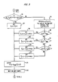
- decoder 100 is realized by programming a DSP unit. Operation of decoder 100 is described in conjunction with the digital program flow chart of Figs. 2 and 3. Figs. 2 and 3 when connected A-A and B-B form a flow chart of a program routine for converting digital samples l n (k) from a second code, e.g., 4-bit ADPCM, to digital samples ⁇ (k) in a first code, e.g., ⁇ 255 PCM. Accordingly, the DSP is initialized via 201. Thereafter, predictor sample estimate Y(k) is computed in operational block 202 in a known manner.
- a second code e.g., 4-bit ADPCM
- Operational blocks 203 and 204 relate to the reception and decoding of the 4-bit differential PCM sample l n (k) and the generation or "finding" of the inverse ADPCM quantized version of l n (k), namely, the quantized version eq(k) of difference signal e(k).
- Operational block 205 causes the digital value of eq(k) to be truncated. That is to say, the bits of eq(k) are limited to the integer portion and any fractional portion is truncated to yield eq'(k).
- Operational block 206 causes reconstructed signal Y,(k) to be computed by adder 118, namely, Quantizer scale factor ⁇ (k) is updated in operational block 116 in known fashion.
- the adaptive predictor 112 coefficients are updated in operational block 208.
- composite noise value a(k) is computed in operational block 209.
- the composite noise value is obtained by first making a trial transmission in output modification unit 119 of decoder 100 of linear reconstructed signal Y r (k).
- Y r (k) is PCM quantized e.g., ⁇ 255 PCM, and then PCM decoded to generate the equivalent of Y(k) in coder 101, which is a linear version of ⁇ (k).
- the composite noise value is computed by the use of equation (1): namely,
- Operational block 210 simulates the upper and lower decision levels for the ADPCM quantizer interval into which sample l n (k) falls: namely, and dl L [l n (k)], respectively, (see Fig. 5).
- step 211 if the evaluation result of step 211 is NO, adjustment of reconstructed signal Y r (k) is necessary to insure that coder 101 will generate an output ADPCM sample l n+1 (k) equal to ADPCM sample In received by decoder 100 and control is transferred to operational block 214.
- Operational block 214 determines the size M(k) of the ⁇ 255 PCM quantizer interval that reconstructed signal Y r (k) falls in. That is, M(k) is used in conjunction with adjustment scaling factor ⁇ in following program steps so that the adjustment to reconstructed signal Y r (k) is neither too large nor too small, which would result in overcorrecting or undercorrecting, respectively, of the reconstructed signal. That is to say, the adjustment to reconstructed signal Y r (k) for compensating for the composite noise should not be so large as to cause the resulting adjusted reconstructed signal Y r (k) to fall in a PCM quantizer interval which is not adjacent to the interval Y r (k) falls in.
- M(k) is also used with adjustment scaling factor 8 when l n (k) is either the maximum ADPCM quantizer interval I MAX or the minimum ADPCM quantizer interval I MI N in order to minimize the amount of quantizer noise introduced. Selection of values for adjustment scaling factors ⁇ and 8 is described below.
- Conditional branch point 215 tests to determine if In(k) is the maximum ADPCM quantizer interval I MAX .
- I MAx is ADPCM quantizer interval 7 of Fig. 5. If the test result is YES, In(k) is in saturation, i.e., the maximum ADPCM quantizer interval and operational block 216 causes reconstructed signal Y r (k) to be adjusted by a scaled value ⁇ ⁇ M(k) to yield an adjusted reconstructed signal Y r (k), namely where in this example 8 equals 0.6. Thereafter, control is transferred to operational block 213.
- conditional branch point 217 determines if l n (k) is the minimum ADPCM quantizer interval or negative saturation, in this example, I MIN is ADPCM quantizer interval -8 of Fig. 5. If the result in step 217 is YES, l n (k) is in negative saturation and operational block 218 causes reconstructed signal Y r (k) to be adjusted also by the scaled value ⁇ ⁇ M(k), to yield an adjusted reconstructed signal Y r (k), namely, Again, it is important to insure that the adjustment to Y r (k) when in positive or negative saturation is not so large that unwanted additional quantizing noise is added.
- step 7 This additional quantizing noise can occur since the upper ADPCM decision level for positive saturation, i.e., step 7, is + ⁇ and the lower ADPCM decision level for negative saturation, i.e., step -8, is - ⁇ . Thereafter, control is transferred to operational block 213.
- conditional branch point 219 determines whether the corresponding composite noise value a(k) is equal to or greater than the upper ADPCM quantizer decision level for l n (k), namely If the result in step 219 is YES, operational block 220 causes an adjusted reconstructed signal Y r (k) to be generated by decreasing the value of reconstructed signal Y r (k) by a scaled value ⁇ M(k), where in this example, ⁇ equals 0.3. This scaled adjustment insures that adjusted reconstructed signal Y r (k) falls in the lower adjacent PCM quantizer interval to the interval that reconstructed signal Y r (k) falls in. Thereafter, control is transferred to operational block 213. Control is transferred to operational block 213.
- operational block 221 causes scaled value ⁇ ⁇ M(k) to be added to reconstructed signal Y,(k), to yield an adjusted reconstructed signal Y r (k), namely,
- the scaled adjustment insures that adjusted reconstructed signal Y r (k) falls in the higher adjacent PCM quantizer interval to the interval that reconstructed signal Y r (k) falls in. Thereafter, control is transferred to operational block 213.
- the adjustment to reconstructed signal Y r (k) insures that the corresponding PCM coded signal ⁇ (k) is in the appropriate PCM quantizer interval so that coder 101 will ultimately generate an ADPCM sample l n+1 (k) equal to l n (k) received by decoder 100.
- Operational block 213 causes adjusted reconstructed signal Y r (k) to be PCM quantized to yield PCM sample ⁇ (k) which it outputted for transmission to a subsequent coder or to be utilized as desired. In this example, ⁇ 255 PCM quantizing is employed. Thereafter, decoder 100 waits in operational block 222 for the next ADPCM sample l n (k) to be received. Then, control is returned to operational block 202 and the ADPCM-to-PCM decoder process is repeated.
- steps 209 through 221 are included in decoder 100 to insure that a subsequent ADPCM coder 101 will ultimately generate an ADPCM sample l n+1 (k) equal to the ADPCM sample In(k) received by decoder 100.
- This is realized by obtaining composite noise value a(k) through making a "trial" PCM transmission of reconstructed signal Y r (k) then, evaluating composite noise value a(k) relative to the upper and lower ADPCM quantizer decision levels for ADPCM sample l n (k). If the composite noise value is not within the decision levels, the reconstructed signal Y r (k) must be adjusted to insure that coder 101 will generate an ADPCM sample equal to the ADPCM sample received by decoder 100.
- An adjustment value is determined dependent on the size M(k) of the PCM quantizer interval that reconstructed signal Y r (k) falls in and a first predetermined adjustment scaling facotr 8 if l n (k) is in saturation and a second predetermined adjustment scaling factor ⁇ if l n (k) is not in saturation. Then, reconstructed signal Y r (k) is adjusted, if necessary, by the adjustment value to yield adjusted reconstructed signal Y r (k).
- the value of the adjustment is dependent on whether sample l n (k) is the maximum ADPCM quantizer interval or the minimum ADPCM quantizer interval or, if not either the maximum or minimum ADPCM quantizer intervals, whether composite noise value a(k) is greater than or equal to the upper ADPCM quantizer decision level dlU[l n (k)] or less than the lower ADPCM quantizer decision level dl L [l n (k)], for l n (k).
- the reconstructed signal value Y r (k) is decreased by ⁇ ⁇ M(k) when the composite noise value a(k) is equal to or greater than the upper decision level dl U [l n (k)] for sample l n (k) and increased by ⁇ ⁇ M(k) when a(k) is less than the lower decision level dl L [l n (k)] for sample l n (k).
- the composite noise a(k) causes the reconstructed signal Y r (k) to fall in either a next higher or next lower PCM quantizer interval than desired, its value is decreased or increased, respectively, so that the adjusted reconstructed signal Y r (k) falls in the desired PCM quantizer interval.
- l n (k) is the most positive or most negative ADPCM quantizer interval, i.e., in saturation, reconstructed signal value Y r (k) is increased or decreased, respectively, by ⁇ ⁇ M(k).
- adjustment scaling factors ⁇ and 8 are employed to insure that reconstructed signal Y r (k) is not over adjusted or under adjusted, thereby insuring that a subsequent PCM-to-ADPCM coder will generate an ADPCM sample l n+1 (k) equal to the ADPCM sample l n received by the present decoder 100.
- the value of adjustment scaling factors ⁇ is dependent on the ADPCM quantizer characteristic being employed and, specifically, on the error boundaries of that characteristic. It is known that the negative slope error boundary is -1.
- the positive slope error boundary y is defined by
- a worst case condition for adjustment scaling factors ⁇ occurs when the composite noise causes the reconstructed signal Y r (k) to fall in a PCM quantizer interval in a different chord than Y(k).
- the positive slope and negative slope error boundaries when superimposed on the PCM quantization error characteristic define the minimum value that adjustment scaling factor ⁇ must be to adjust the reconstructed signal Y r (k) to fall in the proper PCM quantizer interval for coder 101 to generate an ADPCM sample l n+1 (k) equal to the ADPCM sample l n (k) received by decoder 100.
- the minimum value for adjustment scaling factor ⁇ is determined by the ratio of a projection (v) on a horizontal axis of the error boundary segment formed by the positive slope error boundary intersecting the PCM error characteristic in the PCM quantizer interval that reconstructed signal Y,(k) falls in and the size M(k) of the PCM quantizer interval, i.e., Then, it will be apparent to those skilled in the art that In one example, the slope of the positive slope error boundary slope y is approximately 2/3. Therefore, from equation (3) the minimum value for adjustment scaling factor ⁇ is 0.2 in order to properly correct reconstructed signal Y,(k).
- Fig. 4 depicts a flow chart of a program routine for converting digital signals from a first code, e.g., p-law PCM to a second code, e.g., 4-bit ADPCM, namely, the operation of coder 101.
- the DSP is initialized via 401.
- the predictor sample estimate Y(k) is computed via operational block 402.
- Operational block 403 causes reveived PCM samples ⁇ (k) to be decoded and converted to linear PCM form, namely, Y(k).
- Operational block 404 causes the computation of difference signal e(k), which comprises the difference between linear samples Y(k) and predicted sample estimate Y(k), namely, Difference signal e(k) is ADPCM quantized via operational block 405, for example, in accordance with the nonuniform ADPCM quantizer characteristic of Fig. 5, to obtain 4-bit differential PCM output sample l n+1 (k).
- Operational block 406 causes l n+1 (k) to be inverse ADPCM quantized to find vaue eq(k) and, then, the 4-bit differential PCM sample l n+1 (k) is outputted.
- Operational block 407 causes eq(k) to be truncated to yield eq'(k).
- step 410 coder 101 waits in block 411 for the next PCM input sample ⁇ (k). Then, control is transferred to operational block 402 and the PCM-to-ADPCM coder process is repeated.
- Fig. 6 shows in simplified block diagram form a codec including another embodiment of the invention.
- Coder 101 is identical to coder 101 shown in Fig. 1 and operates in accordance with the flow chart shown in Fig. 4. Accordingly, the elements of coder 101 of Fig. 6 have been numbered the same as coder 101 of Fig. 1 and will not be described again in detail.
- Decoder 600 of Fig. 6 is similar to decoder 100 of Fig. 1. Elements of decoder 600 which are the same as those used in decoder 100 of Fig. 1 have been similarly numbered and will not be described again.
- the difference between decoder 600 and decoder 100 is that output adjustment unit 119 (Fig. 1) has been eliminated and PCM output quantizer 601 (Fig. 6) includes an arrangement for controllably adjusting the quantizer interval of PCM samples ⁇ (k) in order to insure that subsequent coder 101 will ultimately generate an ADPCM sample l n+1 (k) equal to the ADPCM sample l n (k) received by decoder 600.
- the adjustment to PCM sample ⁇ (k), if needed, is determined by evaluating composite noise value a(k) for ADPCM sample l n (k), composite noise value a(k) is generated in PCM output quantizer 601.
- the received ADPCM sample l n (k), quantizer scale factor A(k), predictor estimate Y(k) and reconstructed signal Y r (k) are supplied to PCM output quantizer 601.
- Quantizer 601 generates the composite noise value a(k) for ADPCM sample l n (k) which is evaluated relative to the upper and lower dl L [l n (k)] ADPCM quantizer interval decision levels (Fig. 5) for sample l n (k).
- PCM interval for PCM sample ⁇ (k) must be adjusted. The adjustment is up or down one (1) PCM quantizer interval dependent on whether ADPCM sample In(k) is in positive saturation, negative saturation or whether composite noise a(k) is equal to or greater than the upper ADPCM quantizer decision level or less than the lower ADPCM quantizer decision level for sample In(k). Again, this ensures that next subsequent coder 101 will choose the ADPCM quantizer interval as received by decoder 600 and l n+1 (k) equals In(k).
- Decoder 600 and coder 101 are shown in Fig. 6 in block diagram form to facilitate clarity of description. However, decoder 600 and coder 101 are implemented, in this example, in a digital signal processor (DSP), i.e., a programmable integrated circuit for signal processing. Any one of a number of digital signal processing units known in the art may be employed for this purpose. One such DSP unit is manufactured-by Western Electric Company as noted above.
- DSP digital signal processor
- decoder 600 is realized by programming a DSP unit. Therefore, operation of decoder 600 is described in conjunction with the digital program flow chart of Figs. 7 and 8.
- Figs. 7 and 8 when connected C-C and D-D form a flow chart of a program routine for converting digital samples In(k) from a second code, e.g., 4-bit ADPCM, to digital samples ⁇ (k) in a first code, e.g., ⁇ 255 PCM.
- decoder 600 is similar to decoder 100, operation of which is described in the flow chart of Figs. 2 and 3, the steps in the flow chart of Figs. 7 and 8 which are identical to the steps in Figs.
- Step 201 through 210 are identical to those in Fig. 2.
- Operational block 801 causes reconstructed signal Y r (k) generated in step 206to be PCM quantized for obtaining PCM sample ⁇ (k).
- Conditional branch point 211 as in Fig. 3 evaluates the composite noise value a(k) relative to the upper and lower ADPCM interval decision levels for In(k). That is, composite noise value a(k) is tested to determine whether it is equal to or greater than lower decision level and less than the upper decision level If the evaluation result of step 211 is YES, the PCM quantizer interval that PCM sample ⁇ (k) does not need to be adjusted and control is transferred to operational block 804.
- conditional branch point 215 determines if l n (k) is the maximum ADPCM quantizer interval I MAx . If the result of step 215 is YES, operational block 802 causes PCM sample ⁇ (k) to be adjusted up one PCM quantizer interval and, thereafter, control is transferred to operational block 804. If the result of step 215 is NO, conditional branch point 217 determines if In(k) is the minimum ADPCM quantizer interval I MIN .
- step 217 If the result of step 217 is YES, operational block 803 causes PCM sample ⁇ (k) to be adjusted down one PCM quantizer interval and, thereafter, control is transferred to operational block 804. If the result of step 217 is NO, conditional branch point 219 determines whether composite noise value a(k) is equal to or greater than the upper ADPCM quantizer interval decision level for l n (k). If the test result in step 219 is YES, operational block 803 causes PCM sample ⁇ (k) to be adjusted down one PCM quantizer interval and, thereafter, control is transferred to operational block 804. If the result of step 219 is NO, operational block 802 causes PCM sample ⁇ (k) to be adjusted up one PCM quantizer interval and thereafter, control is transferred to operational block 804.
- Operational block 804 causes PCM sample 804 to be outputted for transmission over communication channel 102 (Fig. 6). Thereafter, decoder 600 waits in operational block 222 for the next ADPCM sample In(k) to be received. Then, control is transferred to operational block 202 and the ADPCM-to-PCM decoder process is repeated.
- ADPCM code schemes may be employed.
- an A-law PCM coding scheme may be employed in place of the p-law PCM.
- either the ADPCM or PCM quantizer may employ any non- uniform or uniform quantizing characteristic.
Landscapes
- Engineering & Computer Science (AREA)
- Theoretical Computer Science (AREA)
- Compression, Expansion, Code Conversion, And Decoders (AREA)
- Analogue/Digital Conversion (AREA)
- Transmission And Conversion Of Sensor Element Output (AREA)
Abstract
Claims (4)
Priority Applications (1)
| Application Number | Priority Date | Filing Date | Title |
|---|---|---|---|
| AT84900188T ATE34056T1 (de) | 1982-12-27 | 1983-11-21 | Digitaler dekodierer. |
Applications Claiming Priority (2)
| Application Number | Priority Date | Filing Date | Title |
|---|---|---|---|
| US06/453,502 US4475213A (en) | 1982-12-27 | 1982-12-27 | Digital code converter |
| US453502 | 1982-12-27 |
Publications (3)
| Publication Number | Publication Date |
|---|---|
| EP0131005A1 EP0131005A1 (fr) | 1985-01-16 |
| EP0131005A4 EP0131005A4 (fr) | 1985-07-30 |
| EP0131005B1 true EP0131005B1 (fr) | 1988-05-04 |
Family
ID=23800811
Family Applications (1)
| Application Number | Title | Priority Date | Filing Date |
|---|---|---|---|
| EP84900188A Expired EP0131005B1 (fr) | 1982-12-27 | 1983-11-21 | Décodeur de code numérique |
Country Status (8)
| Country | Link |
|---|---|
| US (1) | US4475213A (fr) |
| EP (1) | EP0131005B1 (fr) |
| JP (1) | JPS60500194A (fr) |
| AU (1) | AU561478B2 (fr) |
| CA (1) | CA1223964A (fr) |
| DE (1) | DE3376516D1 (fr) |
| IT (1) | IT1170279B (fr) |
| WO (1) | WO1984002623A1 (fr) |
Families Citing this family (17)
| Publication number | Priority date | Publication date | Assignee | Title |
|---|---|---|---|---|
| JPS59103423A (ja) * | 1982-12-06 | 1984-06-14 | Nippon Telegr & Teleph Corp <Ntt> | Adpcm−pcm変換装置 |
| US4571736A (en) * | 1983-10-31 | 1986-02-18 | University Of Southwestern Louisiana | Digital communication system employing differential coding and sample robbing |
| US4536741A (en) * | 1983-11-16 | 1985-08-20 | At&T Bell Laboratories | Digital quantizer |
| US4549304A (en) * | 1983-11-28 | 1985-10-22 | Northern Telecom Limited | ADPCM Encoder/decoder with signalling bit insertion |
| US4719642A (en) * | 1985-02-27 | 1988-01-12 | Scientific Atlanta, Inc. | Error detection and concealment using predicted signal values |
| US4748620A (en) * | 1986-02-28 | 1988-05-31 | American Telephone And Telegraph Company, At&T Bell Laboratories | Time stamp and packet virtual sequence numbering for reconstructing information signals from packets |
| US4703477A (en) * | 1986-02-28 | 1987-10-27 | American Telephone And Telegraph Company At&T Bell Laboratories | Packet information field data format |
| US4894823A (en) * | 1986-02-28 | 1990-01-16 | American Telephone And Telegraph Company | Time stamping for packet system nodes |
| US4774496A (en) * | 1986-02-28 | 1988-09-27 | American Telephone And Telegraph Company, At&T Bell Laboratories | Digital encoder and decoder synchronization in the presence of data dropouts |
| US4920534A (en) * | 1986-02-28 | 1990-04-24 | At&T Bell Laboratories | System for controllably eliminating bits from packet information field based on indicator in header and amount of data in packet buffer |
| US4726019A (en) * | 1986-02-28 | 1988-02-16 | American Telephone And Telegraph Company, At&T Bell Laboratories | Digital encoder and decoder synchronization in the presence of late arriving packets |
| IL80103A0 (en) * | 1986-09-21 | 1987-01-30 | Eci Telecom Limited | Adaptive differential pulse code modulation(adpcm)system |
| US5334977A (en) * | 1991-03-08 | 1994-08-02 | Nec Corporation | ADPCM transcoder wherein different bit numbers are used in code conversion |
| US5227878A (en) * | 1991-11-15 | 1993-07-13 | At&T Bell Laboratories | Adaptive coding and decoding of frames and fields of video |
| US6870886B2 (en) * | 1993-12-15 | 2005-03-22 | Koninklijke Philips Electronics N.V. | Method and apparatus for transcoding a digitally compressed high definition television bitstream to a standard definition television bitstream |
| US6167085A (en) * | 1997-07-31 | 2000-12-26 | Sony Corporation | Image data compression |
| CN1622470B (zh) * | 2004-12-24 | 2010-04-21 | 北京中星微电子有限公司 | 一种自适应差分脉冲编码调制解码装置及方法 |
Family Cites Families (7)
| Publication number | Priority date | Publication date | Assignee | Title |
|---|---|---|---|---|
| JPS6016777B2 (ja) * | 1976-12-25 | 1985-04-27 | 株式会社東芝 | 信号伝送方式 |
| US4363024A (en) * | 1977-11-21 | 1982-12-07 | Brokaw Adrian P | Digital-to-analog converter providing multiplicative and linear functions |
| JPS6058614B2 (ja) * | 1978-03-11 | 1985-12-20 | 日本電信電話株式会社 | Dpcm−pcm変換装置 |
| CH640379A5 (de) * | 1978-12-01 | 1983-12-30 | Bbc Brown Boveri & Cie | Verfahren und einrichtung zur signaluebertragung. |
| US4323885A (en) * | 1980-09-29 | 1982-04-06 | Bell Telephone Laboratories, Incorporated | Noise and crosstalk reduction in mid-riser biased encoders |
| US4384278A (en) * | 1981-07-22 | 1983-05-17 | Bell Telephone Laboratories, Incorporated | One-bit codec with slope overload correction |
| JPS59103423A (ja) * | 1982-12-06 | 1984-06-14 | Nippon Telegr & Teleph Corp <Ntt> | Adpcm−pcm変換装置 |
-
1982
- 1982-12-27 US US06/453,502 patent/US4475213A/en not_active Expired - Lifetime
-
1983
- 1983-11-21 WO PCT/US1983/001832 patent/WO1984002623A1/fr not_active Ceased
- 1983-11-21 JP JP59500159A patent/JPS60500194A/ja active Pending
- 1983-11-21 DE DE8484900188T patent/DE3376516D1/de not_active Expired
- 1983-11-21 AU AU23384/84A patent/AU561478B2/en not_active Ceased
- 1983-11-21 EP EP84900188A patent/EP0131005B1/fr not_active Expired
- 1983-11-28 CA CA000442048A patent/CA1223964A/fr not_active Expired
- 1983-12-23 IT IT24377/83A patent/IT1170279B/it active
Also Published As
| Publication number | Publication date |
|---|---|
| IT1170279B (it) | 1987-06-03 |
| DE3376516D1 (en) | 1988-06-09 |
| IT8324377A0 (it) | 1983-12-23 |
| AU2338484A (en) | 1984-07-17 |
| US4475213A (en) | 1984-10-02 |
| WO1984002623A1 (fr) | 1984-07-05 |
| JPS60500194A (ja) | 1985-02-07 |
| AU561478B2 (en) | 1987-05-07 |
| EP0131005A1 (fr) | 1985-01-16 |
| CA1223964A (fr) | 1987-07-07 |
| EP0131005A4 (fr) | 1985-07-30 |
Similar Documents
| Publication | Publication Date | Title |
|---|---|---|
| EP0131005B1 (fr) | Décodeur de code numérique | |
| EP0099397B1 (fr) | Codage adaptif differentiel a modulation par impulsions codees (pcm) | |
| US4518950A (en) | Digital code converter | |
| US4654863A (en) | Wideband adaptive prediction | |
| US4475227A (en) | Adaptive prediction | |
| US4751736A (en) | Variable bit rate speech codec with backward-type prediction and quantization | |
| US4831636A (en) | Coding transmission equipment for carrying out coding with adaptive quantization | |
| US4811396A (en) | Speech coding system | |
| EP0288281B1 (fr) | Systèmes de codage et de décodage MICDA | |
| US4354273A (en) | ADPCM System for speech or like signals | |
| JP2003504654A (ja) | オーディオ信号の符号化効率を向上させる方法 | |
| US4386237A (en) | NIC Processor using variable precision block quantization | |
| US4319082A (en) | Adaptive prediction differential-PCM transmission method and circuit using filtering by sub-bands and spectral analysis | |
| US4191858A (en) | Block digital processing system for nonuniformly encoded digital words | |
| Boddie et al. | Digital signal processor: Adaptive differential pulse-code-modulation coding | |
| JP2809524B2 (ja) | デジタル伝送システムの同期方式 | |
| US6078620A (en) | Method and apparatus for performing adaptive differential pulse code modulation | |
| JPH0774649A (ja) | 可変ディジタル符号化レートによる量子化装置 | |
| JP3130834B2 (ja) | 移動電話機 | |
| CA1226068A (fr) | Quantificateur numerique | |
| Dubnowski et al. | Variable rate coding | |
| JP2584761B2 (ja) | 予測符号化伝送システム | |
| Das | Advances in Digital Communication (Part 1) | |
| KR0138868B1 (ko) | 엘에스피 주파수 양자화 방법 및 양자화기 | |
| Das | Advances in Digital Communication (Part 1) |
Legal Events
| Date | Code | Title | Description |
|---|---|---|---|
| PUAI | Public reference made under article 153(3) epc to a published international application that has entered the european phase |
Free format text: ORIGINAL CODE: 0009012 |
|
| AK | Designated contracting states |
Designated state(s): AT BE CH DE FR GB LI LU NL SE |
|
| 17P | Request for examination filed |
Effective date: 19841206 |
|
| 17Q | First examination report despatched |
Effective date: 19860926 |
|
| GRAA | (expected) grant |
Free format text: ORIGINAL CODE: 0009210 |
|
| AK | Designated contracting states |
Kind code of ref document: B1 Designated state(s): AT BE CH DE FR GB LI LU NL SE |
|
| REF | Corresponds to: |
Ref document number: 34056 Country of ref document: AT Date of ref document: 19880515 Kind code of ref document: T |
|
| REF | Corresponds to: |
Ref document number: 3376516 Country of ref document: DE Date of ref document: 19880609 |
|
| ET | Fr: translation filed | ||
| PG25 | Lapsed in a contracting state [announced via postgrant information from national office to epo] |
Ref country code: LU Free format text: LAPSE BECAUSE OF NON-PAYMENT OF DUE FEES Effective date: 19881130 |
|
| PLBE | No opposition filed within time limit |
Free format text: ORIGINAL CODE: 0009261 |
|
| STAA | Information on the status of an ep patent application or granted ep patent |
Free format text: STATUS: NO OPPOSITION FILED WITHIN TIME LIMIT |
|
| 26N | No opposition filed | ||
| PGFP | Annual fee paid to national office [announced via postgrant information from national office to epo] |
Ref country code: FR Payment date: 19891030 Year of fee payment: 7 Ref country code: DE Payment date: 19891030 Year of fee payment: 7 Ref country code: BE Payment date: 19891030 Year of fee payment: 7 |
|
| PGFP | Annual fee paid to national office [announced via postgrant information from national office to epo] |
Ref country code: SE Payment date: 19891031 Year of fee payment: 7 Ref country code: GB Payment date: 19891031 Year of fee payment: 7 |
|
| PGFP | Annual fee paid to national office [announced via postgrant information from national office to epo] |
Ref country code: CH Payment date: 19891110 Year of fee payment: 7 Ref country code: AT Payment date: 19891110 Year of fee payment: 7 |
|
| PGFP | Annual fee paid to national office [announced via postgrant information from national office to epo] |
Ref country code: NL Payment date: 19891130 Year of fee payment: 7 |
|
| PG25 | Lapsed in a contracting state [announced via postgrant information from national office to epo] |
Ref country code: GB Effective date: 19901121 Ref country code: AT Effective date: 19901121 |
|
| PG25 | Lapsed in a contracting state [announced via postgrant information from national office to epo] |
Ref country code: SE Effective date: 19901122 |
|
| PG25 | Lapsed in a contracting state [announced via postgrant information from national office to epo] |
Ref country code: LI Effective date: 19901130 Ref country code: CH Effective date: 19901130 Ref country code: BE Effective date: 19901130 |
|
| BERE | Be: lapsed |
Owner name: WESTERN ELECTRIC CY INC. Effective date: 19901130 |
|
| PG25 | Lapsed in a contracting state [announced via postgrant information from national office to epo] |
Ref country code: NL Effective date: 19910601 |
|
| NLV4 | Nl: lapsed or anulled due to non-payment of the annual fee | ||
| GBPC | Gb: european patent ceased through non-payment of renewal fee | ||
| PG25 | Lapsed in a contracting state [announced via postgrant information from national office to epo] |
Ref country code: FR Effective date: 19910731 |
|
| REG | Reference to a national code |
Ref country code: CH Ref legal event code: PL |
|
| PG25 | Lapsed in a contracting state [announced via postgrant information from national office to epo] |
Ref country code: DE Effective date: 19910801 |
|
| REG | Reference to a national code |
Ref country code: FR Ref legal event code: ST |
|
| EUG | Se: european patent has lapsed |
Ref document number: 84900188.8 Effective date: 19910705 |