EP0131073B1 - Dispositif pour relâcher un projectile autopropulsé - Google Patents
Dispositif pour relâcher un projectile autopropulsé Download PDFInfo
- Publication number
- EP0131073B1 EP0131073B1 EP83303941A EP83303941A EP0131073B1 EP 0131073 B1 EP0131073 B1 EP 0131073B1 EP 83303941 A EP83303941 A EP 83303941A EP 83303941 A EP83303941 A EP 83303941A EP 0131073 B1 EP0131073 B1 EP 0131073B1
- Authority
- EP
- European Patent Office
- Prior art keywords
- projectile
- nozzle member
- release mechanism
- missile
- fusible
- Prior art date
- Legal status (The legal status is an assumption and is not a legal conclusion. Google has not performed a legal analysis and makes no representation as to the accuracy of the status listed.)
- Expired
Links
- 230000007246 mechanism Effects 0.000 claims description 22
- 238000000926 separation method Methods 0.000 claims description 5
- 230000002093 peripheral effect Effects 0.000 claims description 4
- 230000000295 complement effect Effects 0.000 claims description 3
- 238000010438 heat treatment Methods 0.000 claims description 3
- 239000007789 gas Substances 0.000 description 10
- 238000003754 machining Methods 0.000 description 5
- 238000005219 brazing Methods 0.000 description 4
- 239000000463 material Substances 0.000 description 4
- 238000004519 manufacturing process Methods 0.000 description 3
- 238000009987 spinning Methods 0.000 description 2
- 235000015842 Hesperis Nutrition 0.000 description 1
- 235000012633 Iberis amara Nutrition 0.000 description 1
- 230000004913 activation Effects 0.000 description 1
- 229910045601 alloy Inorganic materials 0.000 description 1
- 239000000956 alloy Substances 0.000 description 1
- 230000000694 effects Effects 0.000 description 1
- 230000008018 melting Effects 0.000 description 1
- 238000002844 melting Methods 0.000 description 1
- 239000003380 propellant Substances 0.000 description 1
- 230000001141 propulsive effect Effects 0.000 description 1
- 230000000452 restraining effect Effects 0.000 description 1
- 229910000679 solder Inorganic materials 0.000 description 1
- 238000005476 soldering Methods 0.000 description 1
- 230000000087 stabilizing effect Effects 0.000 description 1
Images


Classifications
-
- F—MECHANICAL ENGINEERING; LIGHTING; HEATING; WEAPONS; BLASTING
- F41—WEAPONS
- F41F—APPARATUS FOR LAUNCHING PROJECTILES OR MISSILES FROM BARRELS, e.g. CANNONS; LAUNCHERS FOR ROCKETS OR TORPEDOES; HARPOON GUNS
- F41F3/00—Rocket or torpedo launchers
- F41F3/04—Rocket or torpedo launchers for rockets
- F41F3/048—Means for imparting spin to the rocket before launching
-
- F—MECHANICAL ENGINEERING; LIGHTING; HEATING; WEAPONS; BLASTING
- F41—WEAPONS
- F41C—SMALLARMS, e.g. PISTOLS, RIFLES; ACCESSORIES THEREFOR
- F41C27/00—Accessories; Details or attachments not otherwise provided for
- F41C27/06—Adaptations of smallarms for firing grenades, e.g. rifle grenades, or for firing riot-control ammunition; Barrel attachments therefor
-
- F—MECHANICAL ENGINEERING; LIGHTING; HEATING; WEAPONS; BLASTING
- F41—WEAPONS
- F41F—APPARATUS FOR LAUNCHING PROJECTILES OR MISSILES FROM BARRELS, e.g. CANNONS; LAUNCHERS FOR ROCKETS OR TORPEDOES; HARPOON GUNS
- F41F3/00—Rocket or torpedo launchers
- F41F3/04—Rocket or torpedo launchers for rockets
- F41F3/052—Means for securing the rocket in the launching apparatus
Definitions
- This invention relates to projectile release mechanisms for facilitating launching a jet-propelled projectile.
- Such a projectile release mechanism is generally disclosed in US-A-3554078 comprising a projectile support means, a nozzle means extending between the projectile and the projectile support means for securing the projectile to the projectile support means, and fusible joint means in the nozzle means and disposed for heating by high-temperature exhaust gas expelled by the projectile to release the projectile from the projectile support means.
- the nozzle means comprises a three part nozzle assembly of which a fore part is secured to the missile, an aft part is secured to the projectile support means, and an intermediate part constitutes the fusible joint means and is formed by a separate fusible link memberwhich is of silver solder or brazing alloy and is fused to the fore and aft parts of the nozzle assembly to secure them together.
- the separate fusible link member will degrade when heated by the exhaust gas to above its softening or melt temperature thereby to release the projectile for launch.
- the aforesaid generally disclosed projectile release mechanism is characterised in that the nozzle means is a one-piece nozzle member, and the fusible joint means is an integral part of the one-piece nozzle member and is constituted by a fusible wall portion thereof.
- the invention is advantageous in that the nozzle member with its fusible wall portion constitutes a single part structure thereby eliminating any assembly operation with attendant possibility of increased cost and inaccuracy.
- the jet-propelled missile may be a spherical spin-stabilized missile.
- a missile spins about an axis upwardly inclined relative to the intended straight line path of flight and aligned with the thrust axis of the propulsion jet of the missile.
- the missile is released following ignition or activation of the jet propellent within the missile.
- the propulsion is effected by the reaction of the exhaust jet of, for example, a rocket motor housing within the spherical missile shell.
- spherical spin-stabilized missiles are provided in conjunction with attachments secured to the front end of an assault weapon such as a rifle.
- a spin-stabilized missile eliminates the features associated with a ballistic trajectory ordinarily followed by rockets and like jet-propelled projectiles.
- the projectile support means may include rotary means and means for supporting the rotary means for rotation about a spin axis co-axial with the nozzle member, the nozzle member being secured to the rotary means.
- the rotary means would be caused to rotate about its spin axis during launch by the exhaust gases expelled by the missile thereby to effect spinning of the missile prior to its release. Ensuring proper alignment of the missile with its spin axis during initial separation of the fusible wall portion is particularly important, and normally difficulties are experienced in stabilizing missiles during attainment of their desired rotation speed.
- the rotary means may include a register section for receiving the nozzle member, the register section and the nozzle member having complementarily engageable, axially spaced concentric land means which ensure proper alignment of the missile with the spin axis during the period of initial separation of the nozzle member.
- the register section may be of the socket-type.
- the nozzle member may be threaded at opposite ends for engagement with complementarily threaded receptacle means within the register section of the rotary means as well as the missile itself.
- the land means on each of the socket-type register section and the nozzle member may comprise a pair of axially spaced, radially protruding flat ring-type flange members which may be disposed axially outwardly of the fusible wall portion.
- Difficulties are also experienced in coordinating the spinning and release of a spherical spin-stabilized missile. Release of the missile prior to attainment of adequate rotational speed can result in unstable flight. Delay of release after attainment of adequate rotational speed can result in a loss of propulsive range. Release of the missile at the optimum time is ensured by fashioning the fusible wall portion to thermally degrade at the time when the missile has attained adequate rotational speed thereby to release the missile for launch.
- the fusible wall portion may be a peripheral ring portion of the nozzle member of a reduced sectional thickness.
- a plurality of passages may be formed through the reduced ring portion for conducting the gas therethrough.
- the projectile release mechanism of the aforesaid US-A-3 554 078 is also specifically designed to temporarily restrain and automatically release a spherical spin-stabilized missile during spinup, but exhibits the disadvantages previously enumerated.
- a spherical spin-stabilized jet-propelled missile 10 is shown mounted to the front of a barrel 12 of an assault weapon such as a rifle, generally designated 14.
- the rifle shown is a standard M-16A1 military rifle.
- a missile support means generally designated 16, includes a front upper bracket portion, generally designated 18, and a rear upper latch portion, generally designated 20.
- the bracket portion 18 is positioned on the barrel 12 whereby part of the gas emanating from the barrel is channeled through a passageway 22 to a pneumatically actuated pin assembly 24 which is effective to strike a primer on the missile 10 to ignite the rocket propellant therein, as is known in the art.
- the latch 20 simply is provided to lock the support means 16 onto the rifle barrel 12.
- the support means 16 also includes turbine support portions 26 and 27, and a launcher shaft 28.
- the launcher shaft 28 is disposed on an axis 34 upwardly inclined relative to an intended straight line path of flight 36 generally parallel to the axis of the rifle barrel 12.
- the axis 34 is the spin axis of the missile 10: i.e., the motor thrust of the missile rocket motor.
- An axis 36 which defines the line of flight of the missile 10 is the forward velocity component thereof.
- rotary means generally designated 38, includes a turbine 40 having turbine nozzles 42.
- the turbine is fixed to a hub 44 which forms an extension of the shaft 28 ( Figure 2) and which extends rearwardly thereof.
- the shaft 28 protrudes rotatably within the turbine support means 26 and 27 ( Figure 2).
- Appropriate bearings or bushings (not shown) are disposed in the turbine support portions 26 and 27.
- the turbine 40 also has radial passages 48 in communication with turbine nozzles 42 and in communication with a central cavity 50 within a shaft hub 44.
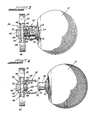
- the rotary means 38 also includes a register section, generally designated 52, formed integrally with and protruding outwardly from the hub 44.
- This register section defines an adapter or socket-type receptacle means for a one-piece or unitary nozzle member 54 which extends between the missile 10 and the rotary means 38 for securing the missile to the rotary means and thus to the support means 16.
- the unitary nozzle member 54 is shown in the enlarged view of Figure 5 as being made from one piece of homogeneous material.
- the unitary nozzle member 54 comprises a disposable, generally tubular member which is threaded at opposite ends thereof, as at 56 and 58, for engagement with the rotary support means 38 and the missile 10. Specifically, the threaded end portion 56 is secured in engagement within a complementarily threaded interior portion 60 ( Figure 3) of the register section 52 of the rotary means 38. The opposite threaded end 58 is secured within a complementarily threaded receptacle (not shown) in the missile 10.
- the unitary nozzle member 54 includes a fusible joint means, generally designated 62, formed integrally with the unitary nozzle member as a fusible wall portion 64 thereof and disposed for heating by high-temperature exhaust gas expelled by the missile 10 to release the missile* from the support means 16 and particularly the rotary means 38.
- the fusible joint means 62 comprises a fusible peripheral ring portion 64 which is reduced in sectional thickness by appropriate machining operations.
- a plurality of passages 66 extend through the reduced ring portion 64 for conducting the exhaust gas through the fusible joint means 62.
- the precise timing of the release of missile 10 can be accurately controlled by the selection of the particular material of which the unitary nozzle is fabricated, the simple operation of machining the peripheral ring portion 64 to a desired thickness and by varying the number and sizes of the passages 66 which, in part, are determined by the amount of heat which can be measured experimentally from the exhaust gases of the missile. No other assembly, brazing, or additional manufacturing operations are required because the nozzle for the missile is fabricated of the one-piece nozzle member 54.
- a pair of vent ports 68 are formed in the register section 52 for the escape of gases which pass through the passages 66 in the fusible ring portion 64.
- the remainder of the gases from the rocket motor within the missile 10 pass through the nozzle member 54 and outwardly through the radial passages 48 and the turbine nozzles 42 to cause the entire rotary means 38 to spin about the shaft 46 relative to the overall support means 16 mounted on the rifle barrel 12.
- the missile 10 After the missile 10 reaches a predetermined spinup, as determined by the material of the nozzle member 54 and the machining of the fusible ring portion 64,thefusible jointwill melt and erode and the missile will separate as shown in Figure 4 and follow the line offlight designated by the axis 36 in Figure 2.
- the unitary nozzle member 54 forms an extension member of the missile 10 and includes a pair of axially spaced, radially protruding, flat ring-type flanges 70 and 72 which define axially spaced concentric surfaces forming annular lands.
- a pair of axially spaced radially inwardly protruding flat lands 74 and 76 are formed on the ' interior of the register section 52 for complementary engagement with the lands 70 and 72, respectively, of the unitary nozzle member 54.
- the complementarily engageable, axially spaced lands prevent wobbling of the missile 10 during spinup which might result in a loss of accuracy in launching the missile along the spin axis 36, and the lands ensure proper alignment of the missile with the spin axis during initial separation of the unitary nozzle member 54 at the fusible ring portion 64.
Landscapes
- Engineering & Computer Science (AREA)
- General Engineering & Computer Science (AREA)
- Aiming, Guidance, Guns With A Light Source, Armor, Camouflage, And Targets (AREA)
- Physical Or Chemical Processes And Apparatus (AREA)
Claims (11)
Priority Applications (1)
| Application Number | Priority Date | Filing Date | Title |
|---|---|---|---|
| DE8383303941T DE3374342D1 (en) | 1983-07-06 | 1983-07-06 | Release apparatus for jet propelled projectiles |
Applications Claiming Priority (1)
| Application Number | Priority Date | Filing Date | Title |
|---|---|---|---|
| US06/250,427 US4403435A (en) | 1981-04-02 | 1981-04-02 | Release and alignment mechanism for jet-propelled projectiles |
Publications (2)
| Publication Number | Publication Date |
|---|---|
| EP0131073A1 EP0131073A1 (fr) | 1985-01-16 |
| EP0131073B1 true EP0131073B1 (fr) | 1987-11-04 |
Family
ID=22947703
Family Applications (4)
| Application Number | Title | Priority Date | Filing Date |
|---|---|---|---|
| EP86115007A Expired EP0226761B1 (fr) | 1981-04-02 | 1983-07-06 | Dispositif pour relâcher et aligner des projectiles autopropulsés |
| EP83303941A Expired EP0131073B1 (fr) | 1981-04-02 | 1983-07-06 | Dispositif pour relâcher un projectile autopropulsé |
| EP83303942A Expired EP0131074B1 (fr) | 1981-04-02 | 1983-07-06 | Dispositif pour relâcher et aligner un projectile autopropulsé |
| EP86114479A Withdrawn EP0223082A3 (fr) | 1981-04-02 | 1983-07-06 | Dispositif pour relâcher et aligner des projectiles autopropulsés |
Family Applications Before (1)
| Application Number | Title | Priority Date | Filing Date |
|---|---|---|---|
| EP86115007A Expired EP0226761B1 (fr) | 1981-04-02 | 1983-07-06 | Dispositif pour relâcher et aligner des projectiles autopropulsés |
Family Applications After (2)
| Application Number | Title | Priority Date | Filing Date |
|---|---|---|---|
| EP83303942A Expired EP0131074B1 (fr) | 1981-04-02 | 1983-07-06 | Dispositif pour relâcher et aligner un projectile autopropulsé |
| EP86114479A Withdrawn EP0223082A3 (fr) | 1981-04-02 | 1983-07-06 | Dispositif pour relâcher et aligner des projectiles autopropulsés |
Country Status (2)
| Country | Link |
|---|---|
| US (1) | US4403435A (fr) |
| EP (4) | EP0226761B1 (fr) |
Families Citing this family (7)
| Publication number | Priority date | Publication date | Assignee | Title |
|---|---|---|---|---|
| NO163425C (no) * | 1987-04-30 | 1990-05-23 | Oerlikon Buehrle Ag | Utformning av et oenskebruddsted ved hekkdelen av et drivspeil for et drivspeilprosjektil. |
| US5067386A (en) * | 1988-05-18 | 1991-11-26 | Brunswick Corporation | Release apparatus for spin stabilized self-propelled projectiles |
| FR2661464B1 (fr) * | 1990-04-27 | 1992-08-14 | Aerospatiale Ste Nat Indle | Dispositif d'assujettissement temporaire d'un objet a un support, a zone de rupture calibree en traction. |
| FR2661465B1 (fr) * | 1990-04-27 | 1992-08-14 | Aerospatiale | Dispositif d'assemblage mecanique temporaire et de separation rapide d'un objet a ejecter lie a un support. |
| US5067385A (en) * | 1990-07-19 | 1991-11-26 | Brunswick Corporation | Method and apparatus for aligning spin-stabilized self-propelled missiles |
| US5115709A (en) * | 1990-08-06 | 1992-05-26 | Brunswick Corporation | Release mechanism for spin-stabilized self-propelled missiles |
| US5171931A (en) * | 1992-01-21 | 1992-12-15 | Brunswick Corporation | Pressure relief means for jet-propelled missiles |
Family Cites Families (10)
| Publication number | Priority date | Publication date | Assignee | Title |
|---|---|---|---|---|
| US932214A (en) * | 1908-10-29 | 1909-08-24 | Krupp Ag | Projectile. |
| US1003079A (en) * | 1910-10-10 | 1911-09-12 | Krupp Ag | Projectile. |
| FR495754A (fr) * | 1917-06-23 | 1919-10-17 | Emilio Piersantelli | Lance-bombes et bombe destinée à etre lancée par ce dispositif |
| US2939449A (en) * | 1955-06-16 | 1960-06-07 | Leonard R Kortick | Launching device and rocket propelled missile therefor |
| US3165836A (en) * | 1962-10-12 | 1965-01-19 | Robert F Magardo | Auxiliary sighting device for grenade launching firearms |
| US3245350A (en) * | 1963-04-29 | 1966-04-12 | Joseph A Kelly | Rocket propelled device for straightline payload transport |
| US3332162A (en) * | 1965-12-22 | 1967-07-25 | Honeywell Inc | Combined rifle and grenade launcher |
| US3442173A (en) * | 1968-05-28 | 1969-05-06 | Us Army | Combined rifle and grenade launcher weapon selectively fired by a single trigger |
| US3554078A (en) * | 1969-02-10 | 1971-01-12 | Joseph S Horvath | Spherical missile and launching means therefor |
| CH520316A (de) * | 1970-02-27 | 1972-03-15 | Oerlikon Buehrle Ag | Drallstabilisiertes Raketengeschoss |
-
1981
- 1981-04-02 US US06/250,427 patent/US4403435A/en not_active Expired - Lifetime
-
1983
- 1983-07-06 EP EP86115007A patent/EP0226761B1/fr not_active Expired
- 1983-07-06 EP EP83303941A patent/EP0131073B1/fr not_active Expired
- 1983-07-06 EP EP83303942A patent/EP0131074B1/fr not_active Expired
- 1983-07-06 EP EP86114479A patent/EP0223082A3/fr not_active Withdrawn
Also Published As
| Publication number | Publication date |
|---|---|
| EP0226761A3 (en) | 1987-09-30 |
| EP0223082A2 (fr) | 1987-05-27 |
| EP0131074A1 (fr) | 1985-01-16 |
| EP0131073A1 (fr) | 1985-01-16 |
| EP0226761A2 (fr) | 1987-07-01 |
| EP0131074B1 (fr) | 1987-12-02 |
| EP0226761B1 (fr) | 1989-01-11 |
| US4403435A (en) | 1983-09-13 |
| EP0223082A3 (fr) | 1987-09-16 |
Similar Documents
| Publication | Publication Date | Title |
|---|---|---|
| US7947938B2 (en) | Methods and apparatus for projectile guidance | |
| US4488489A (en) | Ordnance system having a warhead with secondary elements as a payload | |
| US4800816A (en) | Delay discarding sabot projectile | |
| US20120181375A1 (en) | Modular Guided Projectile | |
| US3167016A (en) | Rocket propelled missile | |
| US4676136A (en) | Apparatus for recoilless firing of projectiles from a lauching tube | |
| EP0131073B1 (fr) | Dispositif pour relâcher un projectile autopropulsé | |
| US5078336A (en) | Spin-stabilized missile with plug nozzle | |
| US12601575B2 (en) | Range extension device | |
| US4395836A (en) | Release apparatus for jet-propelled projectiles | |
| US5067386A (en) | Release apparatus for spin stabilized self-propelled projectiles | |
| RU2751311C1 (ru) | Способ увеличения дальности полета активно-реактивного снаряда и активно-реактивный снаряд с моноблочной комбинированной двигательной установкой (варианты) | |
| US3554078A (en) | Spherical missile and launching means therefor | |
| US3915091A (en) | Rocket powered round | |
| US2835170A (en) | Rocket launcher | |
| KR850001280B1 (ko) | 제트추진식 발사체 발사장치 | |
| AU2023342907A1 (en) | Improved range extension device | |
| EP0373128A2 (fr) | Dispositif d'allumage | |
| RU2785835C1 (ru) | Способ увеличения дальности полёта артиллерийского снаряда с ракетно-прямоточным двигателем и реализующий его артиллерийский снаряд (варианты) | |
| GB2148461A (en) | Hollow charge projectile | |
| US4258625A (en) | Ball-actuated tubular projectile | |
| KR850001281B1 (ko) | 제트추진식 발사체 발사 및 조정장치 | |
| EP0467515B1 (fr) | Méthode et appareil pour aligner des projectiles autopropulsés stabilisés par rotation | |
| EP0131665A1 (fr) | Projectile autopropulsé à charge propulsive et explosive unique | |
| US5115709A (en) | Release mechanism for spin-stabilized self-propelled missiles |
Legal Events
| Date | Code | Title | Description |
|---|---|---|---|
| PUAI | Public reference made under article 153(3) epc to a published international application that has entered the european phase |
Free format text: ORIGINAL CODE: 0009012 |
|
| AK | Designated contracting states |
Designated state(s): DE FR GB SE |
|
| 17P | Request for examination filed |
Effective date: 19850208 |
|
| 17Q | First examination report despatched |
Effective date: 19860417 |
|
| GRAA | (expected) grant |
Free format text: ORIGINAL CODE: 0009210 |
|
| AK | Designated contracting states |
Kind code of ref document: B1 Designated state(s): DE FR GB SE |
|
| REF | Corresponds to: |
Ref document number: 3374342 Country of ref document: DE Date of ref document: 19871210 |
|
| ET | Fr: translation filed | ||
| PLBE | No opposition filed within time limit |
Free format text: ORIGINAL CODE: 0009261 |
|
| STAA | Information on the status of an ep patent application or granted ep patent |
Free format text: STATUS: NO OPPOSITION FILED WITHIN TIME LIMIT |
|
| 26N | No opposition filed | ||
| PGFP | Annual fee paid to national office [announced via postgrant information from national office to epo] |
Ref country code: FR Payment date: 19930610 Year of fee payment: 11 |
|
| PGFP | Annual fee paid to national office [announced via postgrant information from national office to epo] |
Ref country code: DE Payment date: 19930618 Year of fee payment: 11 |
|
| PGFP | Annual fee paid to national office [announced via postgrant information from national office to epo] |
Ref country code: GB Payment date: 19930624 Year of fee payment: 11 |
|
| PG25 | Lapsed in a contracting state [announced via postgrant information from national office to epo] |
Ref country code: GB Effective date: 19940706 |
|
| EAL | Se: european patent in force in sweden |
Ref document number: 83303941.5 |
|
| GBPC | Gb: european patent ceased through non-payment of renewal fee |
Effective date: 19940706 |
|
| PG25 | Lapsed in a contracting state [announced via postgrant information from national office to epo] |
Ref country code: FR Effective date: 19950331 |
|
| PG25 | Lapsed in a contracting state [announced via postgrant information from national office to epo] |
Ref country code: DE Effective date: 19950401 |
|
| REG | Reference to a national code |
Ref country code: FR Ref legal event code: ST |
|
| PGFP | Annual fee paid to national office [announced via postgrant information from national office to epo] |
Ref country code: SE Payment date: 19960618 Year of fee payment: 14 |
|
| PG25 | Lapsed in a contracting state [announced via postgrant information from national office to epo] |
Ref country code: SE Effective date: 19970707 |
|
| EUG | Se: european patent has lapsed |
Ref document number: 83303941.5 |