EP0131074A1 - Vorrichtung zum Freigeben und Ausrichten rückstossgetriebener Geschosse - Google Patents
Vorrichtung zum Freigeben und Ausrichten rückstossgetriebener Geschosse Download PDFInfo
- Publication number
- EP0131074A1 EP0131074A1 EP83303942A EP83303942A EP0131074A1 EP 0131074 A1 EP0131074 A1 EP 0131074A1 EP 83303942 A EP83303942 A EP 83303942A EP 83303942 A EP83303942 A EP 83303942A EP 0131074 A1 EP0131074 A1 EP 0131074A1
- Authority
- EP
- European Patent Office
- Prior art keywords
- nozzle
- projectile
- release mechanism
- axis
- receptacle
- Prior art date
- Legal status (The legal status is an assumption and is not a legal conclusion. Google has not performed a legal analysis and makes no representation as to the accuracy of the status listed.)
- Granted
Links
- 230000007246 mechanism Effects 0.000 title claims abstract description 34
- 238000000926 separation method Methods 0.000 claims abstract description 32
- 230000000295 complement effect Effects 0.000 claims abstract description 10
- 239000007789 gas Substances 0.000 claims abstract description 10
- 238000010438 heat treatment Methods 0.000 claims abstract description 7
- 230000013011 mating Effects 0.000 claims 1
- 238000005219 brazing Methods 0.000 description 2
- 239000003380 propellant Substances 0.000 description 2
- 230000000452 restraining effect Effects 0.000 description 2
- 235000015842 Hesperis Nutrition 0.000 description 1
- 235000012633 Iberis amara Nutrition 0.000 description 1
- 230000004913 activation Effects 0.000 description 1
- 239000000956 alloy Substances 0.000 description 1
- 229910045601 alloy Inorganic materials 0.000 description 1
- 238000010276 construction Methods 0.000 description 1
- 238000004519 manufacturing process Methods 0.000 description 1
- 239000000463 material Substances 0.000 description 1
- 230000008018 melting Effects 0.000 description 1
- 238000002844 melting Methods 0.000 description 1
- 239000002184 metal Substances 0.000 description 1
- 229910052751 metal Inorganic materials 0.000 description 1
- 230000001141 propulsive effect Effects 0.000 description 1
- 238000009987 spinning Methods 0.000 description 1
- 230000003313 weakening effect Effects 0.000 description 1
Images
Classifications
-
- F—MECHANICAL ENGINEERING; LIGHTING; HEATING; WEAPONS; BLASTING
- F41—WEAPONS
- F41F—APPARATUS FOR LAUNCHING PROJECTILES OR MISSILES FROM BARRELS, e.g. CANNONS; LAUNCHERS FOR ROCKETS OR TORPEDOES; HARPOON GUNS
- F41F3/00—Rocket or torpedo launchers
- F41F3/04—Rocket or torpedo launchers for rockets
- F41F3/048—Means for imparting spin to the rocket before launching
-
- F—MECHANICAL ENGINEERING; LIGHTING; HEATING; WEAPONS; BLASTING
- F41—WEAPONS
- F41C—SMALLARMS, e.g. PISTOLS, RIFLES; ACCESSORIES THEREFOR
- F41C27/00—Accessories; Details or attachments not otherwise provided for
- F41C27/06—Adaptations of smallarms for firing grenades, e.g. rifle grenades, or for firing riot-control ammunition; Barrel attachments therefor
-
- F—MECHANICAL ENGINEERING; LIGHTING; HEATING; WEAPONS; BLASTING
- F41—WEAPONS
- F41F—APPARATUS FOR LAUNCHING PROJECTILES OR MISSILES FROM BARRELS, e.g. CANNONS; LAUNCHERS FOR ROCKETS OR TORPEDOES; HARPOON GUNS
- F41F3/00—Rocket or torpedo launchers
- F41F3/04—Rocket or torpedo launchers for rockets
- F41F3/052—Means for securing the rocket in the launching apparatus
Definitions
- This invention relates to a projectile release mechanism for facilitating launching of a jet-propelled projectile, particularly a spherical spin-stabilized missile, and for insuring proper alignment of the missile with its spin axis during initial separation.
- the projectiles spins about an axis upwardly inclined relative to the intended straight line path of flight and aligned with the thrust axis of the propulsion jet of the missile.
- the missile is released following ignition or activation of the jet propellant within the missile.
- the propulsion is effected by the reaction of the exhaust jet of, for example, a rocket motor housed within the spherical missile shell.
- Such spin-stabilized spherical jet-propelled missiles experience difficulties in remaining stabilized during attainment of desired rotational speed and in coordinating the spinning and release of the missile. Release of the missile prior to attainment of adequate rotational speed can result in unstable flight. Delay of release after attainment of adequate rotational speed can result in a loss of propulsive range.
- the separate fusible link member is of the nature of a brazing alloy serving as one part of a nozzle assembly to secure the rocket to the rotary support means.
- the fusible link member is brazed between two separate fore and aft nozzle portions which are permanently secured to the missile and to the support means, respectively, as by threaded engagements.
- a new and improved nozzle assembly is disclosed.
- the nozzle assembly includes a unitary nozzle member having fusible joint means formed integrally therewith, between the missile and the rotary support means, thereby eliminating the assembly and brazing operations of prior devices as shown in the Horvath patent, and thereby considerably reducing manufacturing costs and improving accuracy.
- the fore and aft sections of the unitary nozzle, forwardly and rearwardly of the fusible joint means are permanently fixed to the missile and to the support means, respectively, as by threaded engagements.
- the present invention is directed to providing a further new and improved nozzle assembly in which the projectile support means includes open-ended receptacle means out of which the fore and aft sections of the nozzle can move on fusing and separation of the fusible joint means.
- the invention also includes novel means for accommodating thermal expansion of the nozzle member, particularly at the fusible joint means.
- An object, therefore, of the present invention is to provide a new and improved projectile release mechanism for facilitating launching a jet-propelled projectile.
- Another object of the invention is to provide a new and improved projectile release mechanism which includes a novel construction providing separation of fore and aft sections of the nozzle member on opposite sides of the fusible joint or separation means.
- a further object of the invention is to provide novel retaining means for the nozzle member to insure proper alignment of the missile with its spin axis during initial separation of the separation means.
- Still a further object of the invention is to provide means for accommodating any thermal expansion of the nozzle member, particularly in the area of the fusible joint means.
- the release mechanism includes a nozzle member extending from the projectile, including fusible joint means for heating by high-temperature exhaust gases expelled by the projectile to release the projectile.
- the nozzle extends rearwardly of the projectile into rotary support means for rotation of the projectile about a spin axis coaxial with the nozzle secured between the projectile and the rotary support means.
- the support means includes an open-ended receptacle generally coaxial with the axis of the nozzle. Means is provided for retaining the nozzle in the receptacle and permitting fore and aft sections of the nozzle to move out of the open ends of the receptacle on fusing and separation of the fusible joint means.
- the retaining means includes forwardly and rearwardly facing shoulder portions on the support means, forward and rearward of the fusible joint means, and complementarily engageable shoulder portions on the nozzle.
- the forwardly facing shoulder portion on the support means comprises a forwardly opening conical section generally concentric with the axis of the nozzle and engageable with a complementary conical shoulder portion on the nozzle.
- Biasing means is provided operatively associated with the nozzle and effective to maintain the shoulder portions of the nozzle member in engagement with the shoulder portions of the support means until complete separation of the fusible joint means. This accommodates any thermal expansion of the nozzle, particularly in the area of the fusible joint means.
- the biasing means comprises a plurality of spring members equally spaced about and concentric with the axis of the nozzle. The spring members bias a rear, forwardly facing flange on the nozzle into engagement with the rearwardly facing shoulder portion on the support means. It should be understood that the invention contemplates employing a biasing means directly between the nozzle and the support means.
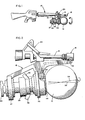
- a spherical spin-stabilized jet-propelled missile 10 is shown mounted to the front of a barrel 12 of an assault weapon such as a rifle, generally designated 14.
- the rifle shown is a standard M-16A1 military rifle.
- a missile support means generally designated 16, includes a front upper bracket portion, generally designated 18, and a rear upper latch portion, generally designated 20.
- Bracket portion 18 is positioned on the barrel 12 whereby part of the gas emanating from the barrel is channeled through a passageway 22 ( Figure 2) to a pneumatically actuated pin assembly 24 which is effective to strike a primer on missile 10 to ignite the rocket propellant therein as is known in the art.
- Latch 20 simply is provided to lock support means 16 onto the rifle barrel.
- Support means 16 also includes turbine support portions 26 and 27, and rotary means, generally designated 28.
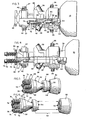
- Rotary means 28 is disposed on an axis 34 upwardly inclined relative to an extended straight line path of flight 36 generally parallel to the axis of rifle barrel 12.
- axis 34 is the spin axis of missile 10: i.e., the motor thrust of the missile rocket motor.
- Axis 36 defines the line of flight of the missile and is the forward velocity component thereof.
- rotary means 28 includes a plurality of turbine nozzles 38.
- the rotary means is rotatable within turbine support portions 26 and 27 by bearing means 40 and 42, respectively.
- the rotary means forms an open-ended receptacle having a forward open end 44 and a rear open end 46.
- the receptacle is generally coaxial with spin axis 34 ( Figure 2).
- a nozzle assembly generally designated 48, includes a fore section 50 and an aft section 52 ( Figures 4-6) joined by an integral fusible joint means, generally designated 54.
- the fusible joint means is similar to that shown in the aforementioned application and is disposed for heating by high-temperature exhaust gases expelled by missile 10 to release the missile from support means 16 and particularly rotary means 28. More particularly, a plurality of passages 56 extend through the nozzle for conducting the exhaust gas through fusible joint means 54, through internal passages 58, and out through turbine nozzles 38. The remainder of the gases from the rocket motor within missile 10 pass axially through the fore section of the nozzle, through an internal passage 60 and out through turbine nozzles 38.
- Means is provided for retaining the nozzle in the receptacle defined by the rotary means and for permitting the fore and aft sections of the nozzle to separate and move out of the front and rear ends of the receptacle on separation at the fusible joint means. More particularly, a forwardly facing shoulder portion 60 and a rearwardly facing shoulder portion 62 are provided on the rotary support means 28.
- the forwardly facing shoulder portion comprises a forwardly opening conical section generally concentric with the axis of the nozzle assembly and terminating forwardly at the open end 44 of the receptacle.
- the nozzle assembly is provided with a complementary rearwardly facing shoulder portion 64 and a forwardly facing shoulder portion 66 for engaging the forwardly and rearwardly facing shoulder portions 60 and 62, respectively.
- the rearwardly facing shoulder portion 64 of the nozzle assembly has a conical conformation complementary to the conical section 60 on the interior of the rotary support means.
- Biasing means is provided operatively associated with the nozzle assembly and effective to maintain the conical shoulder portions 60, 64 in engagement until complete separation of the fusible joint means, thereby accommodating any thermal expansion of the nozzle, particularly in the area of the fusible joint means.
- a ring-like flange 68 is slidably mounted on a flat, circular land portion 70 of the aft section 52 of the nozzle assembly. This ring defines the forwardly facing shoulder portion 66 which engages the rearwardly facing shoulder portion 62 to retain the nozzle assembly in the receptacle defined by rotary support means 28.
- a plurality of coil springs 72 are equally spaced about and concentric with the axis of the nozzle assembly.
- each spring is sandwiched between the ring flange and a washer 74 seated forwardly of a head portion 76 of a bolt or shaft 78.
- Shafts 78 protrude through the ring flange and are secured to the rear side of the aft section 52 of the nozzle assembly.
- the ring flange is biased by the springs against the rearwardly facing shoulder portion 62 of the rotary support means. With the ring flange so seated, the springs are effective to bias the entire nozzle assembly rearwardly of the open-ended receptacle defined by the rotary support means.
- the nozzle assembly is preloaded by springs 72 and the springs are effective to accommodate any thermal expansion by biasing the aft section of the nozzle assembly rearwardly and constantly maintaining the conical section of the nozzle assembly in proper aligned engagement until complete separation of the fusible joint means. It should be understood that the invention contemplates the use of a single spring or other equivalent biasing means for preloading the nozzle assembly.
Landscapes
- Engineering & Computer Science (AREA)
- General Engineering & Computer Science (AREA)
- Aiming, Guidance, Guns With A Light Source, Armor, Camouflage, And Targets (AREA)
- Physical Or Chemical Processes And Apparatus (AREA)
Priority Applications (2)
| Application Number | Priority Date | Filing Date | Title |
|---|---|---|---|
| DE8686115007T DE3378928D1 (en) | 1983-07-06 | 1983-07-06 | Release and alignment mechanism for jet-propelled projectiles |
| DE8383303942T DE3374810D1 (en) | 1983-07-06 | 1983-07-06 | Release and alignment mechanism for jet-propelled projectiles |
Applications Claiming Priority (1)
| Application Number | Priority Date | Filing Date | Title |
|---|---|---|---|
| US06/250,427 US4403435A (en) | 1981-04-02 | 1981-04-02 | Release and alignment mechanism for jet-propelled projectiles |
Related Child Applications (3)
| Application Number | Title | Priority Date | Filing Date |
|---|---|---|---|
| EP86114479A Division EP0223082A3 (de) | 1981-04-02 | 1983-07-06 | Vorrichtung zum Freigeben und Ausrichten rückstossgetriebener Geschosse |
| EP86114479.8 Division-Into | 1986-10-18 | ||
| EP86115007.6 Division-Into | 1986-10-29 |
Publications (2)
| Publication Number | Publication Date |
|---|---|
| EP0131074A1 true EP0131074A1 (de) | 1985-01-16 |
| EP0131074B1 EP0131074B1 (de) | 1987-12-02 |
Family
ID=22947703
Family Applications (4)
| Application Number | Title | Priority Date | Filing Date |
|---|---|---|---|
| EP86115007A Expired EP0226761B1 (de) | 1981-04-02 | 1983-07-06 | Vorrichtung zum Freigeben und Ausrichten rückstossgetriebener Geschosse |
| EP83303941A Expired EP0131073B1 (de) | 1981-04-02 | 1983-07-06 | Vorrichtung zum Freigeben rückstossgetriebener Geschosse |
| EP83303942A Expired EP0131074B1 (de) | 1981-04-02 | 1983-07-06 | Vorrichtung zum Freigeben und Ausrichten rückstossgetriebener Geschosse |
| EP86114479A Withdrawn EP0223082A3 (de) | 1981-04-02 | 1983-07-06 | Vorrichtung zum Freigeben und Ausrichten rückstossgetriebener Geschosse |
Family Applications Before (2)
| Application Number | Title | Priority Date | Filing Date |
|---|---|---|---|
| EP86115007A Expired EP0226761B1 (de) | 1981-04-02 | 1983-07-06 | Vorrichtung zum Freigeben und Ausrichten rückstossgetriebener Geschosse |
| EP83303941A Expired EP0131073B1 (de) | 1981-04-02 | 1983-07-06 | Vorrichtung zum Freigeben rückstossgetriebener Geschosse |
Family Applications After (1)
| Application Number | Title | Priority Date | Filing Date |
|---|---|---|---|
| EP86114479A Withdrawn EP0223082A3 (de) | 1981-04-02 | 1983-07-06 | Vorrichtung zum Freigeben und Ausrichten rückstossgetriebener Geschosse |
Country Status (2)
| Country | Link |
|---|---|
| US (1) | US4403435A (de) |
| EP (4) | EP0226761B1 (de) |
Families Citing this family (7)
| Publication number | Priority date | Publication date | Assignee | Title |
|---|---|---|---|---|
| NO163425C (no) * | 1987-04-30 | 1990-05-23 | Oerlikon Buehrle Ag | Utformning av et oenskebruddsted ved hekkdelen av et drivspeil for et drivspeilprosjektil. |
| US5067386A (en) * | 1988-05-18 | 1991-11-26 | Brunswick Corporation | Release apparatus for spin stabilized self-propelled projectiles |
| FR2661464B1 (fr) * | 1990-04-27 | 1992-08-14 | Aerospatiale Ste Nat Indle | Dispositif d'assujettissement temporaire d'un objet a un support, a zone de rupture calibree en traction. |
| FR2661465B1 (fr) * | 1990-04-27 | 1992-08-14 | Aerospatiale | Dispositif d'assemblage mecanique temporaire et de separation rapide d'un objet a ejecter lie a un support. |
| US5067385A (en) * | 1990-07-19 | 1991-11-26 | Brunswick Corporation | Method and apparatus for aligning spin-stabilized self-propelled missiles |
| US5115709A (en) * | 1990-08-06 | 1992-05-26 | Brunswick Corporation | Release mechanism for spin-stabilized self-propelled missiles |
| US5171931A (en) * | 1992-01-21 | 1992-12-15 | Brunswick Corporation | Pressure relief means for jet-propelled missiles |
Citations (2)
| Publication number | Priority date | Publication date | Assignee | Title |
|---|---|---|---|---|
| US3245350A (en) * | 1963-04-29 | 1966-04-12 | Joseph A Kelly | Rocket propelled device for straightline payload transport |
| US3554078A (en) * | 1969-02-10 | 1971-01-12 | Joseph S Horvath | Spherical missile and launching means therefor |
Family Cites Families (8)
| Publication number | Priority date | Publication date | Assignee | Title |
|---|---|---|---|---|
| US932214A (en) * | 1908-10-29 | 1909-08-24 | Krupp Ag | Projectile. |
| US1003079A (en) * | 1910-10-10 | 1911-09-12 | Krupp Ag | Projectile. |
| FR495754A (fr) * | 1917-06-23 | 1919-10-17 | Emilio Piersantelli | Lance-bombes et bombe destinée à etre lancée par ce dispositif |
| US2939449A (en) * | 1955-06-16 | 1960-06-07 | Leonard R Kortick | Launching device and rocket propelled missile therefor |
| US3165836A (en) * | 1962-10-12 | 1965-01-19 | Robert F Magardo | Auxiliary sighting device for grenade launching firearms |
| US3332162A (en) * | 1965-12-22 | 1967-07-25 | Honeywell Inc | Combined rifle and grenade launcher |
| US3442173A (en) * | 1968-05-28 | 1969-05-06 | Us Army | Combined rifle and grenade launcher weapon selectively fired by a single trigger |
| CH520316A (de) * | 1970-02-27 | 1972-03-15 | Oerlikon Buehrle Ag | Drallstabilisiertes Raketengeschoss |
-
1981
- 1981-04-02 US US06/250,427 patent/US4403435A/en not_active Expired - Lifetime
-
1983
- 1983-07-06 EP EP86115007A patent/EP0226761B1/de not_active Expired
- 1983-07-06 EP EP83303941A patent/EP0131073B1/de not_active Expired
- 1983-07-06 EP EP83303942A patent/EP0131074B1/de not_active Expired
- 1983-07-06 EP EP86114479A patent/EP0223082A3/de not_active Withdrawn
Patent Citations (2)
| Publication number | Priority date | Publication date | Assignee | Title |
|---|---|---|---|---|
| US3245350A (en) * | 1963-04-29 | 1966-04-12 | Joseph A Kelly | Rocket propelled device for straightline payload transport |
| US3554078A (en) * | 1969-02-10 | 1971-01-12 | Joseph S Horvath | Spherical missile and launching means therefor |
Also Published As
| Publication number | Publication date |
|---|---|
| EP0226761A3 (en) | 1987-09-30 |
| EP0223082A2 (de) | 1987-05-27 |
| EP0131073A1 (de) | 1985-01-16 |
| EP0226761A2 (de) | 1987-07-01 |
| EP0131074B1 (de) | 1987-12-02 |
| EP0131073B1 (de) | 1987-11-04 |
| EP0226761B1 (de) | 1989-01-11 |
| US4403435A (en) | 1983-09-13 |
| EP0223082A3 (de) | 1987-09-16 |
Similar Documents
| Publication | Publication Date | Title |
|---|---|---|
| US7947938B2 (en) | Methods and apparatus for projectile guidance | |
| US4488489A (en) | Ordnance system having a warhead with secondary elements as a payload | |
| US4574702A (en) | Armour-piercing high-explosive projectile with cartridge | |
| US3388666A (en) | Rifle grenade | |
| US20120181375A1 (en) | Modular Guided Projectile | |
| US3167016A (en) | Rocket propelled missile | |
| US5078336A (en) | Spin-stabilized missile with plug nozzle | |
| US4403435A (en) | Release and alignment mechanism for jet-propelled projectiles | |
| EP0171534B1 (de) | Kugelfang und Kugelabweiser für Gewehrgranate | |
| US5067386A (en) | Release apparatus for spin stabilized self-propelled projectiles | |
| US6035631A (en) | Safety in solid fuel rocket motors | |
| US4395836A (en) | Release apparatus for jet-propelled projectiles | |
| US3554078A (en) | Spherical missile and launching means therefor | |
| US4406210A (en) | Jet-propelled missile with single propellant-explosive | |
| KR850001281B1 (ko) | 제트추진식 발사체 발사 및 조정장치 | |
| US4258625A (en) | Ball-actuated tubular projectile | |
| US4693434A (en) | Self-deploying stabilizing-vane assembly for projectile | |
| US5402720A (en) | Booster-missile self-aligning adapter | |
| US5115709A (en) | Release mechanism for spin-stabilized self-propelled missiles | |
| KR850001280B1 (ko) | 제트추진식 발사체 발사장치 | |
| CA2225964C (en) | Improved safety in solid fuel rocket motors | |
| EP0467515B1 (de) | Verfahren und Vorrichtung zum Ausrichten von drallstabilisierten Selbstantriebsgeschossen | |
| US4757765A (en) | Rotational projectile | |
| RU2125229C1 (ru) | Реактивный артиллерийский снаряд | |
| EP0131665A1 (de) | Rückstossgetriebenes Geschoss mit kombinierter Treib- und Explosivladung |
Legal Events
| Date | Code | Title | Description |
|---|---|---|---|
| PUAI | Public reference made under article 153(3) epc to a published international application that has entered the european phase |
Free format text: ORIGINAL CODE: 0009012 |
|
| 17P | Request for examination filed |
Effective date: 19840601 |
|
| AK | Designated contracting states |
Designated state(s): DE FR GB SE |
|
| 17Q | First examination report despatched |
Effective date: 19860417 |
|
| GRAA | (expected) grant |
Free format text: ORIGINAL CODE: 0009210 |
|
| AK | Designated contracting states |
Kind code of ref document: B1 Designated state(s): DE FR GB SE |
|
| REF | Corresponds to: |
Ref document number: 3374810 Country of ref document: DE Date of ref document: 19880114 |
|
| ET | Fr: translation filed | ||
| PLBE | No opposition filed within time limit |
Free format text: ORIGINAL CODE: 0009261 |
|
| STAA | Information on the status of an ep patent application or granted ep patent |
Free format text: STATUS: NO OPPOSITION FILED WITHIN TIME LIMIT |
|
| 26N | No opposition filed | ||
| PGFP | Annual fee paid to national office [announced via postgrant information from national office to epo] |
Ref country code: FR Payment date: 19930610 Year of fee payment: 11 |
|
| PGFP | Annual fee paid to national office [announced via postgrant information from national office to epo] |
Ref country code: DE Payment date: 19930618 Year of fee payment: 11 |
|
| PGFP | Annual fee paid to national office [announced via postgrant information from national office to epo] |
Ref country code: GB Payment date: 19930624 Year of fee payment: 11 |
|
| PG25 | Lapsed in a contracting state [announced via postgrant information from national office to epo] |
Ref country code: GB Effective date: 19940706 |
|
| EAL | Se: european patent in force in sweden |
Ref document number: 83303942.3 |
|
| GBPC | Gb: european patent ceased through non-payment of renewal fee |
Effective date: 19940706 |
|
| PG25 | Lapsed in a contracting state [announced via postgrant information from national office to epo] |
Ref country code: FR Effective date: 19950331 |
|
| PG25 | Lapsed in a contracting state [announced via postgrant information from national office to epo] |
Ref country code: DE Effective date: 19950401 |
|
| REG | Reference to a national code |
Ref country code: FR Ref legal event code: ST |
|
| PGFP | Annual fee paid to national office [announced via postgrant information from national office to epo] |
Ref country code: SE Payment date: 19960618 Year of fee payment: 14 |
|
| PG25 | Lapsed in a contracting state [announced via postgrant information from national office to epo] |
Ref country code: SE Effective date: 19970707 |
|
| EUG | Se: european patent has lapsed |
Ref document number: 83303942.3 |