EP0131077B1 - Zusätzliche Vorrichtung für Streckzwirnmaschinen zum Herstellen von Multifilamentgarnen mit S- oder Z-Dralleffekt - Google Patents
Zusätzliche Vorrichtung für Streckzwirnmaschinen zum Herstellen von Multifilamentgarnen mit S- oder Z-Dralleffekt Download PDFInfo
- Publication number
- EP0131077B1 EP0131077B1 EP83308027A EP83308027A EP0131077B1 EP 0131077 B1 EP0131077 B1 EP 0131077B1 EP 83308027 A EP83308027 A EP 83308027A EP 83308027 A EP83308027 A EP 83308027A EP 0131077 B1 EP0131077 B1 EP 0131077B1
- Authority
- EP
- European Patent Office
- Prior art keywords
- roll
- yarn
- cylindrical
- truncated
- drawtwister
- Prior art date
- Legal status (The legal status is an assumption and is not a legal conclusion. Google has not performed a legal analysis and makes no representation as to the accuracy of the status listed.)
- Expired
Links
- 230000000694 effects Effects 0.000 title claims description 5
- 229920002994 synthetic fiber Polymers 0.000 claims description 3
- 239000004758 synthetic textile Substances 0.000 claims description 2
- 238000004519 manufacturing process Methods 0.000 description 13
- 238000010438 heat treatment Methods 0.000 description 5
- 238000000034 method Methods 0.000 description 4
- 239000004753 textile Substances 0.000 description 3
- 238000005265 energy consumption Methods 0.000 description 2
- 239000004744 fabric Substances 0.000 description 2
- 229910000792 Monel Inorganic materials 0.000 description 1
- 230000005611 electricity Effects 0.000 description 1
- 238000005516 engineering process Methods 0.000 description 1
- 230000001747 exhibiting effect Effects 0.000 description 1
- 239000012467 final product Substances 0.000 description 1
- 238000011065 in-situ storage Methods 0.000 description 1
- 238000009434 installation Methods 0.000 description 1
- 238000012423 maintenance Methods 0.000 description 1
- 239000007769 metal material Substances 0.000 description 1
- 230000004048 modification Effects 0.000 description 1
- 238000012986 modification Methods 0.000 description 1
- 239000000047 product Substances 0.000 description 1
- 229910001220 stainless steel Inorganic materials 0.000 description 1
- 239000010935 stainless steel Substances 0.000 description 1
- 239000012209 synthetic fiber Substances 0.000 description 1
- 230000001131 transforming effect Effects 0.000 description 1
Images


Classifications
-
- D—TEXTILES; PAPER
- D02—YARNS; MECHANICAL FINISHING OF YARNS OR ROPES; WARPING OR BEAMING
- D02G—CRIMPING OR CURLING FIBRES, FILAMENTS, THREADS, OR YARNS; YARNS OR THREADS
- D02G1/00—Producing crimped or curled fibres, filaments, yarns, or threads, giving them latent characteristics
- D02G1/02—Producing crimped or curled fibres, filaments, yarns, or threads, giving them latent characteristics by twisting, fixing the twist and backtwisting, i.e. by imparting false twist
- D02G1/04—Devices for imparting false twist
- D02G1/08—Rollers or other friction causing elements
Definitions
- the present invention relates to the manufacture of textile multifilament yarns and, in particular, to a device for twisting multifilament yarns in drawtwister machines.
- the machines equipped with magnetic spindles work at speeds ranging from 800,000 to 1,000,000 rpm. in order to produce multifilament yarns of approximately 1,000-5,000 twists per meter.
- U.S. Patent 3 559 391 discloses a device for the production of torque yarn, comprising a freely rotatable yarn driven roller having a cylindrical yarn driven end and a tapered yarn twist end for imparting twist to the yarn.
- German Patent DE. 2 460 031 discloses a device for producing a false-twist yarn, comprising a freely rotatable cylindrical roll and a yarn driven roll in the form substantially of a truncated cone whose lateral walls are of a conical-concave shape, said truncated roll rotating freely around an axis extending substantially at a right angle relative to the axis of said cylindrical roll.
- a device to be attached to drawtwister machines for drawtwisting synthetic textile multifilament yarns to produce yarns with S or Z twist comprising a freely rotatable cylindrical roll and a roll substantially in the form of a truncated cone whose lateral walls comprise a conical-concave zone, said truncated roll being freely rotatable around an axis extending substantially at right angles to the axis of said cylindrical roll, and said truncated roll being spaced a predetermined distance from said cylindrical roll, characterised in that said device further comprises a mounting plate, in that said cylindrical roll is rotatable around a shaft secured to said plate, in that the lateral walls of said truncated cone further comprise a cylindrical zone, and in that said truncated roll can rotate freely around a shaft secured to said plate, wherein, in use, the non-texturized yarn will be caused to pass first around the conical-concave zone of said roll, then around the cylindrical
- An embodiment of the present invention may provide a simple and low cost device, which may be attached to drawtwister machines to manufacture twisted multifilament yarns with either S or Z twist.
- An embodiment of the present invention may permit a high productivity to be achieved in machines equipped with the twisting device in comparison with the productivity obtained with conventional machines.
- the productivity obtained may reach approximately 600-900 meters of yarn/minute in each device, in comparison with the 300/500 m/minute obtained in the conventional machines equipped with magnetic spindles.
- An embodiment of the present invention may enable one to obtain a low unit cost of production in comparison with those obtained with conventional machines.
- Multifilament yarn twisted with a device of the present invention may be of high quality, with a great number of twists per meter, and of good elasticity (in the range of 5-25%), making it possible to obtain fabrics for panty-hoses, stockings and the like of great transparency and smoothness.
- Conventional.drawtwister machines equipped with a twisting device of the present invention may operate with a low energy consumption in comparison with the high energy consumption of the conventional texturizing machines.
- An embodiment of the present invention may be designed to be very simple, small and of low cost.
- An embodiment of the invention may enable, in situ, a modification of existing drawtwister machines, transforming them into machines that at a very low cost and without delay of time caused by stopping the manufacturing procedure, provide a special type of yarn highly suitable for manufacturing panty-hose or stockings and the like.
- An operating process in a drawtwister machine modified according to the present invention may be very simple in comparison with the process employed for instance, in magnetic spindles machines ("texturizers").
- a device may include a pair of twisting rollers mounted to rotate freely in shafts, the axes of which are arranged at a substantial angle between them, the shafts being in spaced apart and parallel planes, one of the twisting rolls is a straight cylinder mounted on a fixed shaft whose axis is perpendicular to a supporting plate and the other is frustrum with concave walls and with a determined radius of curvature mounted on a shaft whose axis is parallel to the surface of the supporting plate.
- the supporting plate of the twisting device may be installed on a surface of the drawtwister machine so that the shaft of the concave roll forms an angle of about 40°-50° relative to an imaginary line connecting the yarn fastening roller and the surface of the godet.
- the twist of the yarn is set by heating the filament by a suitable heating element which heats the yarn before it passes around the twisting rollers.
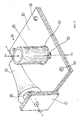
- a twisting device 1 embodying the invention comprises a base plate 11 having a substantially square shape where a cylindrical roll 12 is mounted to rotate freely around a shaft 13 which extends along the Y-Y axis of the cylindrical roll 12.
- cylindrical roll 12 can be hollow and furnished with a flange 14 on the end adjacent plate 11 which projects radially outwardly from the surface of the lateral walls of the cylindrical roller.
- a twisting roll 15 is located laterally spaced from the cylindrical roll 12 and has substantially the shape of a frustrum having slightly concave lateral walls. Twisting roll 15 is shown in Figure 3 in greater detail.
- the shaft 16 of twisting roll 15 which extends along -the X-X axis forms a substantially right angle relative to shaft 13 (axis Y-Y of cylindrical roll 12) and consequently lies substantially parallel to the upper face of base plate 11.
- the conical-concave roll 15 is mounted to rotate freelyaround shaft 16 which is fixed to a console 17 located at a substantially right angle relative to the upper face of base plate 11.
- the base plate 11 can be furnished with holes 18, through which bolts (not shown) can be screwed into the drawtwister machine.
- FIG. 1 The position of the rolls 12 and 15 which are shown in Figure 1, comprise a twisting device for producing yarns with "S" twist.
- Figures 2 shows a device 1a in which can be observed that the conical-concave roll 15 is installed with its axial shaft X-X located in a totally opposed position with respect to the position shown in Figure 1.
- This Figure 2 location for rolls 12 and 15 comprise a twisting device for producing yarn with z twist.
- the twisting roll 15 is shown schematically and partially, in a section view.
- the body of the roll has a substantially truncated shape, being preferentially hollow and with lateral walls defined by a concave zone 20, with a radius of curvature R and a cylindrical zone 21 of length A and diameter d; the base 22 of the twisting roll 15, of diameter D, is provided with a bearing 23, for instance, of the needle type or similar, which enables the twisting roll 15 to rotate freely around shaft 16.
- the length L of the conical-concave twisting roll 15 is between 20 and 90 mm.
- Twisting rolls 12 and 15 are preferably made of metallic material with a suitable surface hardness such as, for instance, stainless steel, monel metal or similar.
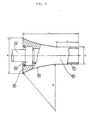
- a continuous textile yarn of synthetic fiber 31, fed from a creel (not shown) is wound around a fastening roll 32, which is frictionally driven by the impeller shaft 33 which rotates at a predetermined angular speed.
- the yarn 31, after making contact with one yarn guide 34, is wound (one or more time) around a heating element 35.
- the heating element 35 operated by electricity or by other suitable means, can rotate, if desired, freely around its axle due to the frictional drive of yarn 31, as will be later explained.
- the friction resulting from the drive of yarn 31 around the heater 35 causes the heating reel to rotate freely.
- the yarn 31 is heated up to the proper temperature to set up the twist on the yarn 31 which will be produced by means of the conical-concave twisting roll 15 and the cylindrical roll 12; the rollers rotating freely under the action of the frictional drive produced by the yarn 31.
- the drive of the yarn at high linear speed on the conical-concave twisting roll 15 causes the yarn to slide up and down on the concave surface 20 of the roll 15, thus producing an S twist effect on the yarn 31 which twist is due to the temperature provided by heater 35.
- the yarn 31, already twisted, is transferred from the godet 36 to a cops or winder cylinder (not shown) and later is knit by circular machines to manufacture panty-hose stockings and other products.
- Figure 5 illustrates the position of the device 1a a of Figure 2, in which Z twist is obtained on the yarn 31 in the same way that device 1 (shown in Figure 4), produces S twist.
- the device 1 is located to one side or to the other side of the yarn path from the fastening roller 32 to the godet 36, depending upon whether S of Z twisting is required.
- the device is mounted via its supporting plate 11 on the support surface V of the drawtwister machine in such a way that the shaft 16 of the concave roll 15 forms an angle of about 40 0- 60 0 relative to an imaginary line connecting the fastening roller 32 and the surface of the godet 36 i.e. relative to the yarn as it is driven from the fastening coller 32 by the godet 36. Also, the shaft 13 of the roll 12 extends transversely of the yarn.
Landscapes
- Engineering & Computer Science (AREA)
- Mechanical Engineering (AREA)
- Textile Engineering (AREA)
- Yarns And Mechanical Finishing Of Yarns Or Ropes (AREA)
Claims (6)


Priority Applications (1)
| Application Number | Priority Date | Filing Date | Title |
|---|---|---|---|
| AT83308027T ATE31089T1 (de) | 1983-07-07 | 1983-12-29 | Zusaetzliche vorrichtung fuer streckzwirnmaschinen zum herstellen von multifilamentgarnen mit s- oder z-dralleffekt. |
Applications Claiming Priority (2)
| Application Number | Priority Date | Filing Date | Title |
|---|---|---|---|
| US511703 | 1983-07-07 | ||
| US06/511,703 US4562694A (en) | 1983-07-07 | 1983-07-07 | Device for attachment to drawtwister machines to produce multifilament yarns with S or Z twist effect |
Publications (2)
| Publication Number | Publication Date |
|---|---|
| EP0131077A1 EP0131077A1 (de) | 1985-01-16 |
| EP0131077B1 true EP0131077B1 (de) | 1987-11-25 |
Family
ID=24036076
Family Applications (1)
| Application Number | Title | Priority Date | Filing Date |
|---|---|---|---|
| EP83308027A Expired EP0131077B1 (de) | 1983-07-07 | 1983-12-29 | Zusätzliche Vorrichtung für Streckzwirnmaschinen zum Herstellen von Multifilamentgarnen mit S- oder Z-Dralleffekt |
Country Status (6)
| Country | Link |
|---|---|
| US (1) | US4562694A (de) |
| EP (1) | EP0131077B1 (de) |
| AR (1) | AR231313A1 (de) |
| AT (1) | ATE31089T1 (de) |
| DE (1) | DE3374699D1 (de) |
| MX (1) | MX158044A (de) |
Families Citing this family (3)
| Publication number | Priority date | Publication date | Assignee | Title |
|---|---|---|---|---|
| DE3519102A1 (de) * | 1985-05-28 | 1986-12-04 | Fritz 7347 Bad Überkingen Stahlecker | Friktionswalze fuer eine vorrichtung zum oe-friktionsspinnen |
| DE3735942A1 (de) * | 1987-10-23 | 1989-05-03 | Barmag Barmer Maschf | Falschdrallrolle |
| CN115627568A (zh) * | 2022-11-29 | 2023-01-20 | 绍兴华裕纺机有限公司 | 一种加弹机的导纱机构 |
Family Cites Families (13)
| Publication number | Priority date | Publication date | Assignee | Title |
|---|---|---|---|---|
| US28117A (en) * | 1860-05-01 | Smut-machine | ||
| BE565672A (de) * | 1957-05-08 | |||
| NL253655A (de) * | 1959-07-15 | |||
| CH397493A (de) * | 1963-01-05 | 1965-08-15 | Rieter Ag Maschf | Vorrichtung zum Überwachen des Fadenlaufes an Streckzwirnmaschinen und dergleichen |
| US3327461A (en) * | 1965-06-17 | 1967-06-27 | Turbo Machine Co | Apparatus and method for producing false twist in yarn |
| US3559391A (en) * | 1968-06-28 | 1971-02-02 | American Enka Corp | Production of torque yarn |
| GB1280470A (en) * | 1968-10-31 | 1972-07-05 | Scragg & Sons | False twisting apparatus |
| BE754695A (fr) * | 1969-10-27 | 1971-01-18 | Glanzstoff Ag | Dispositif servant a donner une fausse torsion aux monofilaments ou auxfiles sans fin |
| US3735575A (en) * | 1970-12-23 | 1973-05-29 | S Hattori | Spinning apparatus for continuous operation |
| USRE28117E (en) | 1971-10-14 | 1974-08-13 | Production op torque yarn | |
| US3782090A (en) * | 1971-12-08 | 1974-01-01 | Chadbourn Inc | Method and apparatus for producing textured yarn |
| US3816989A (en) * | 1973-08-08 | 1974-06-18 | Akzona Inc | Yarn driven friction falsetwister |
| CH567114A5 (de) * | 1973-12-31 | 1975-09-30 | Gehring Rudolf |
-
1983
- 1983-07-07 US US06/511,703 patent/US4562694A/en not_active Expired - Fee Related
- 1983-10-06 AR AR294466A patent/AR231313A1/es active
- 1983-10-13 MX MX199103A patent/MX158044A/es unknown
- 1983-12-29 DE DE8383308027T patent/DE3374699D1/de not_active Expired
- 1983-12-29 EP EP83308027A patent/EP0131077B1/de not_active Expired
- 1983-12-29 AT AT83308027T patent/ATE31089T1/de active
Also Published As
| Publication number | Publication date |
|---|---|
| AR231313A1 (es) | 1984-10-31 |
| ATE31089T1 (de) | 1987-12-15 |
| EP0131077A1 (de) | 1985-01-16 |
| US4562694A (en) | 1986-01-07 |
| MX158044A (es) | 1988-12-29 |
| DE3374699D1 (en) | 1988-01-07 |
Similar Documents
| Publication | Publication Date | Title |
|---|---|---|
| US4351146A (en) | Process and device for producing a yarn having alternate twists of opposite directions | |
| US2914810A (en) | Crimping of textile fibres | |
| US4033103A (en) | Process and apparatus for producing a variable diameter alternate twist yarn | |
| US4736578A (en) | Method for forming a slub yarn | |
| US4027467A (en) | Uniroll false twist device and method | |
| US2999351A (en) | Bulky yarn | |
| US3680302A (en) | False twisting apparatus | |
| US4103481A (en) | Variable diameter yarn | |
| US2983026A (en) | Method for producing crimped fiber | |
| US3527043A (en) | Means and process for producing a false twist by friction | |
| US2979882A (en) | Method and apparatus for stretching and twisting continuous filament yarn | |
| GB2041997A (en) | Method and apparatus for producing spun yarn characteristics in synthetic multi-filament yarns | |
| EP0131077B1 (de) | Zusätzliche Vorrichtung für Streckzwirnmaschinen zum Herstellen von Multifilamentgarnen mit S- oder Z-Dralleffekt | |
| US3805344A (en) | Variable feed means for jet texturing apparatus | |
| GB2045288A (en) | Process for producing a combination yarn | |
| US6854167B2 (en) | Treatment of filament yarns to provide spun-like characteristics and yarns and fabrics produced thereby | |
| US7127784B2 (en) | Treatment of filament yarns to provide spun-like characteristics and yarns and fabrics produced thereby | |
| US3330104A (en) | False twist spindle with auxiliary reverse-twist element | |
| JPH07103499B2 (ja) | 仮撚装置 | |
| US4335572A (en) | Process for production of textured yarn useful in the formation of a crepe fabric | |
| CN219430211U (zh) | 用于生产纱线的系统 | |
| US4112667A (en) | Apparatus and process suitable for twist-drawing a yarn | |
| CA2051856A1 (en) | Short and long fiber composite yarn and process and apparatus for producing same | |
| US3835632A (en) | Draw-texturing apparatus | |
| US3153272A (en) | Apparatus for the production of crimped or bulk yarn |
Legal Events
| Date | Code | Title | Description |
|---|---|---|---|
| PUAI | Public reference made under article 153(3) epc to a published international application that has entered the european phase |
Free format text: ORIGINAL CODE: 0009012 |
|
| AK | Designated contracting states |
Designated state(s): AT BE CH DE FR GB IT LI LU NL SE |
|
| 17P | Request for examination filed |
Effective date: 19850703 |
|
| 17Q | First examination report despatched |
Effective date: 19860606 |
|
| GRAA | (expected) grant |
Free format text: ORIGINAL CODE: 0009210 |
|
| ITF | It: translation for a ep patent filed | ||
| AK | Designated contracting states |
Kind code of ref document: B1 Designated state(s): AT BE CH DE FR GB IT LI LU NL SE |
|
| REF | Corresponds to: |
Ref document number: 31089 Country of ref document: AT Date of ref document: 19871215 Kind code of ref document: T |
|
| PG25 | Lapsed in a contracting state [announced via postgrant information from national office to epo] |
Ref country code: LU Free format text: LAPSE BECAUSE OF NON-PAYMENT OF DUE FEES Effective date: 19871231 |
|
| REF | Corresponds to: |
Ref document number: 3374699 Country of ref document: DE Date of ref document: 19880107 |
|
| ET | Fr: translation filed | ||
| PLBE | No opposition filed within time limit |
Free format text: ORIGINAL CODE: 0009261 |
|
| STAA | Information on the status of an ep patent application or granted ep patent |
Free format text: STATUS: NO OPPOSITION FILED WITHIN TIME LIMIT |
|
| 26N | No opposition filed | ||
| PGFP | Annual fee paid to national office [announced via postgrant information from national office to epo] |
Ref country code: GB Payment date: 19901207 Year of fee payment: 8 |
|
| PGFP | Annual fee paid to national office [announced via postgrant information from national office to epo] |
Ref country code: SE Payment date: 19901219 Year of fee payment: 8 Ref country code: LU Payment date: 19901219 Year of fee payment: 8 |
|
| PGFP | Annual fee paid to national office [announced via postgrant information from national office to epo] |
Ref country code: CH Payment date: 19901224 Year of fee payment: 8 |
|
| PGFP | Annual fee paid to national office [announced via postgrant information from national office to epo] |
Ref country code: AT Payment date: 19901227 Year of fee payment: 8 |
|
| PGFP | Annual fee paid to national office [announced via postgrant information from national office to epo] |
Ref country code: NL Payment date: 19901231 Year of fee payment: 8 |
|
| PGFP | Annual fee paid to national office [announced via postgrant information from national office to epo] |
Ref country code: BE Payment date: 19910114 Year of fee payment: 8 |
|
| PGFP | Annual fee paid to national office [announced via postgrant information from national office to epo] |
Ref country code: DE Payment date: 19910115 Year of fee payment: 8 |
|
| PGFP | Annual fee paid to national office [announced via postgrant information from national office to epo] |
Ref country code: FR Payment date: 19910124 Year of fee payment: 8 |
|
| EPTA | Lu: last paid annual fee | ||
| PG25 | Lapsed in a contracting state [announced via postgrant information from national office to epo] |
Ref country code: GB Effective date: 19911229 Ref country code: AT Effective date: 19911229 |
|
| PG25 | Lapsed in a contracting state [announced via postgrant information from national office to epo] |
Ref country code: SE Effective date: 19911230 |
|
| ITTA | It: last paid annual fee | ||
| PG25 | Lapsed in a contracting state [announced via postgrant information from national office to epo] |
Ref country code: LI Effective date: 19911231 Ref country code: CH Effective date: 19911231 Ref country code: BE Effective date: 19911231 |
|
| BERE | Be: lapsed |
Owner name: SUMAR CESAR Effective date: 19911231 |
|
| PG25 | Lapsed in a contracting state [announced via postgrant information from national office to epo] |
Ref country code: NL Effective date: 19920701 |
|
| NLV4 | Nl: lapsed or anulled due to non-payment of the annual fee | ||
| GBPC | Gb: european patent ceased through non-payment of renewal fee | ||
| PG25 | Lapsed in a contracting state [announced via postgrant information from national office to epo] |
Ref country code: FR Effective date: 19920831 |
|
| REG | Reference to a national code |
Ref country code: CH Ref legal event code: PL |
|
| PG25 | Lapsed in a contracting state [announced via postgrant information from national office to epo] |
Ref country code: DE Effective date: 19920901 |
|
| REG | Reference to a national code |
Ref country code: FR Ref legal event code: ST |
|
| EUG | Se: european patent has lapsed |
Ref document number: 83308027.8 Effective date: 19920704 |