EP0131213A2 - Echangeur de chaleur - Google Patents
Echangeur de chaleur Download PDFInfo
- Publication number
- EP0131213A2 EP0131213A2 EP84107485A EP84107485A EP0131213A2 EP 0131213 A2 EP0131213 A2 EP 0131213A2 EP 84107485 A EP84107485 A EP 84107485A EP 84107485 A EP84107485 A EP 84107485A EP 0131213 A2 EP0131213 A2 EP 0131213A2
- Authority
- EP
- European Patent Office
- Prior art keywords
- liquid
- tube
- heat
- heat exchanger
- level
- Prior art date
- Legal status (The legal status is an assumption and is not a legal conclusion. Google has not performed a legal analysis and makes no representation as to the accuracy of the status listed.)
- Granted
Links
- 239000007788 liquid Substances 0.000 claims abstract description 52
- 239000003507 refrigerant Substances 0.000 claims abstract description 24
- 238000002347 injection Methods 0.000 claims abstract description 3
- 239000007924 injection Substances 0.000 claims abstract description 3
- 238000012856 packing Methods 0.000 claims description 2
- 230000000630 rising effect Effects 0.000 claims 1
- 239000010409 thin film Substances 0.000 abstract description 8
- 238000009835 boiling Methods 0.000 abstract description 4
- 239000012535 impurity Substances 0.000 abstract description 3
- 238000012546 transfer Methods 0.000 description 11
- 239000007787 solid Substances 0.000 description 6
- 230000015572 biosynthetic process Effects 0.000 description 5
- 238000001816 cooling Methods 0.000 description 5
- 239000010408 film Substances 0.000 description 5
- XLYOFNOQVPJJNP-UHFFFAOYSA-N water Substances O XLYOFNOQVPJJNP-UHFFFAOYSA-N 0.000 description 5
- 238000004140 cleaning Methods 0.000 description 4
- 239000003673 groundwater Substances 0.000 description 3
- 239000002245 particle Substances 0.000 description 3
- 238000009826 distribution Methods 0.000 description 2
- 239000002184 metal Substances 0.000 description 2
- 230000009467 reduction Effects 0.000 description 2
- 206010010774 Constipation Diseases 0.000 description 1
- 238000010521 absorption reaction Methods 0.000 description 1
- 244000052616 bacterial pathogen Species 0.000 description 1
- 230000009172 bursting Effects 0.000 description 1
- 230000001427 coherent effect Effects 0.000 description 1
- 239000000356 contaminant Substances 0.000 description 1
- 238000011109 contamination Methods 0.000 description 1
- 239000000498 cooling water Substances 0.000 description 1
- 238000013461 design Methods 0.000 description 1
- 230000000694 effects Effects 0.000 description 1
- 238000000605 extraction Methods 0.000 description 1
- 239000000945 filler Substances 0.000 description 1
- 239000012530 fluid Substances 0.000 description 1
- 239000011521 glass Substances 0.000 description 1
- 230000002706 hydrostatic effect Effects 0.000 description 1
- 230000003993 interaction Effects 0.000 description 1
- 238000012423 maintenance Methods 0.000 description 1
- 230000007257 malfunction Effects 0.000 description 1
- 238000004519 manufacturing process Methods 0.000 description 1
- 230000007246 mechanism Effects 0.000 description 1
- 238000000034 method Methods 0.000 description 1
- 239000008267 milk Substances 0.000 description 1
- 210000004080 milk Anatomy 0.000 description 1
- 235000013336 milk Nutrition 0.000 description 1
- 239000000203 mixture Substances 0.000 description 1
- 238000005191 phase separation Methods 0.000 description 1
- 230000008569 process Effects 0.000 description 1
- 230000008439 repair process Effects 0.000 description 1
- 239000004576 sand Substances 0.000 description 1
- 238000000926 separation method Methods 0.000 description 1
- 239000000126 substance Substances 0.000 description 1
- 238000009423 ventilation Methods 0.000 description 1
- 230000000007 visual effect Effects 0.000 description 1
Images



Classifications
-
- F—MECHANICAL ENGINEERING; LIGHTING; HEATING; WEAPONS; BLASTING
- F28—HEAT EXCHANGE IN GENERAL
- F28D—HEAT-EXCHANGE APPARATUS, NOT PROVIDED FOR IN ANOTHER SUBCLASS, IN WHICH THE HEAT-EXCHANGE MEDIA DO NOT COME INTO DIRECT CONTACT
- F28D3/00—Heat-exchange apparatus having stationary conduit assemblies for one heat-exchange medium only, the media being in contact with different sides of the conduit wall, in which the other heat-exchange medium flows in a continuous film, or trickles freely, over the conduits
- F28D3/04—Distributing arrangements
-
- Y—GENERAL TAGGING OF NEW TECHNOLOGICAL DEVELOPMENTS; GENERAL TAGGING OF CROSS-SECTIONAL TECHNOLOGIES SPANNING OVER SEVERAL SECTIONS OF THE IPC; TECHNICAL SUBJECTS COVERED BY FORMER USPC CROSS-REFERENCE ART COLLECTIONS [XRACs] AND DIGESTS
- Y10—TECHNICAL SUBJECTS COVERED BY FORMER USPC
- Y10S—TECHNICAL SUBJECTS COVERED BY FORMER USPC CROSS-REFERENCE ART COLLECTIONS [XRACs] AND DIGESTS
- Y10S165/00—Heat exchange
- Y10S165/163—Heat exchange including a means to form fluid film on heat transfer surface, e.g. trickle
- Y10S165/168—Film formed on interior surface of container or pipe
- Y10S165/169—Film formed on interior surface of container or pipe inside of vertical pipe
- Y10S165/17—Distributor "cap" mounted in top end of pipe
Definitions
- the invention relates to a thin-film heat exchanger which is suitable for the use of liquids contaminated by solids as a heat-emitting medium, such as e.g. for the use of river, groundwater or the like.
- a heat source for heat pumps which is clearly superior to the heat exchangers previously used for such purposes in terms of heat transfer coefficient and space requirements.
- Preferred embodiments of the heat exchanger according to the invention also permit continuous operation which is not interrupted by cleaning work, even with heat-emitting liquids heavily contaminated by solids.
- Evaporator tubes or plate evaporators placed in the heat-emitting medium (e.g. water) and flowed through by the refrigerant allow a lower cooling limit of approx. + 1 ° C to be maintained, but have a much larger space requirement than tubular boiler evaporators and a somewhat poorer heat transfer coefficient of approx. 300 W / m 2 K. Cleaning the outside of the pipes or plates is cumbersome because they are up to 1.5 m deep in the water-carrying channel and their maximum distance is 100 mm.
- the heat-emitting medium e.g. water
- the best heat transfer coefficient of approx. 800 W / m 2 K and the lowest cooling limit of + 0.2 ° C have plate and pipe trickle coolers, ie horizontal pipes or plates through which refrigerant flows, on the outer surfaces of which the heat-emitting liquid flows down as a thin film. This must therefore be arranged above the pipes or plates ten rows of holes in the bottom of a distribution trough with narrow bores, which naturally tend to clog when solid contaminants are present. The cleaning of the surfaces of the pipes or plates also requires labor and business interruption, since the side covers have to be removed for this.
- the introduction of the liquid into the exchange tube which is flared downwards to a cone, via a weir, such as according to DAS 1 164 990, or through several tangentially arranged feeders, such as according to CH-PS 600 279, does not guarantee that the liquid flow neither at the point of introduction nor at tears off the wall of the conical extension, but forms the desired coherent thin film over the entire length of the inner tube wall.
- the measure proposed in DD-PS 46 722 is to fasten on the upper part of the heat exchange tube a hollow, rotationally symmetrical body which projects into it and which is expanded towards the bottom and is open at the top and bottom by at least three mounting ribs, the outwardly curved surface of which guides the liquid onto the inner wall of the tube shouldn’t guarantee film formation on the inside wall of the pipe in the intended form, because the width of the opening shown between the rotating body and the inside wall of the pipe would be much too large, quite apart from the fact that the shape of the rotating body also does not allow the liquid flow to be torn off smoothly allows its lower edge so that at least a significant part of the liquid supplied does not even reach the inner tube wall, but falls freely downwards. Even a considerable narrowing of the annular gap would not result in a reliable and uniform film formation due to the unfavorable shape of the rotary body, but would bring with it the same risk of clogging as in known tube and plate trickle coolers.
- the object of the present invention is therefore to provide a thin-film heat exchanger with upright pipes, which is free from the disadvantages of the known coolers, in particular re results in extraordinarily high heat transfer coefficients and also allowable cooling limits, which are still superior to the lowest known to date, and also allow for special embodiments which, even when using heavily with solids such as sand, mud and the like.
- Contaminated liquids as heat-emitting medium enables continuous operation not interrupted by cleaning and / or repair work.
- One of the advantages of the cooler according to the invention is, inter alia, the possibility of allowing water to run down to temperatures below 0 ° C, for example to -1 / 2 ° C, in the supercooled state and thus to better utilize its heat content than is possible with known heat exchangers.
- the distributor head is preferably axially displaceable in the heat exchange tube and is provided with a bolt projecting from the tube, by means of which it can be set in up and down movement.
- Preferred embodiments of the invention relate to advantageous embodiments of the distributor head and devices which automatically start the movement of the distributor head when the annular gap becomes blocked and, if this measure does not remove the blockage in the case of particularly heavy soiling, temporarily remove the distributor head completely from the pipe. Further embodiments relate to a special management of the refrigerant circuit, which improves the heat transfer on the refrigerant side and the efficiency of the phase separation of the refrigerant, and measures to further improve the heat transfer on the refrigerant side by reducing the space available to the refrigerant in the evaporator.
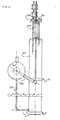
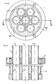
- FIGS. 1 and 2 the application of the invention for operating a heat pump is described below, for example.
- the heat-emitting medium such as river ground or cooling water 15 reaches a - not shown - supply line in a flow vessel 37, which sits tightly on the upper tube plate 6, in which the heat exchange tubes 1 of the tube bundle are tightly fitted, for example, rolled, u .zw. so that their appropriately somewhat extended upper ends 4 protrude beyond the tube plate 6.
- the lower tube ends 5 are rolled into the lower tube plate 7 so that they protrude somewhat downwards.
- the two tube plates 6 and 7 close the boiler 2, in which the heat-absorbing medium 35 surrounding the tubes 1 is located, at the top and bottom.
- the heat-emitting liquid reaches the heat exchange tubes 1 and is passed through the distributor heads 3 (cf. FIGS. 4, 5 and 6, 7) attached in the upper region thereof, for example conically expanded in its lower region narrow annular gap 14 led to the inner wall 13 of the tubes 1.
- the lowermost circumference 12 of each distributor head is designed such that the liquid flowing down at this point is torn off smoothly, flows out through the annular gap 14, is applied as a thin film to the inner tube wall 13 and as such flows down the inner tube wall. In order to ensure a smooth tearing off of the liquid at the lowest circumference 12, this is of sharp-edged design, as shown in the figures.
- the underside of the distributor head 3 is preferably hollowed out, for example conically, in such a way that there is a recess 124 which rises sharply from the lowest circumference 12.
- the radius of the lowest circumference 12 is preferably matched to the inner radius of the tube 1 so that the width of the annular gap 14 is approximately in the range of 0.1 to 1 mm, preferably 0.3 to 0.7 mm.
- FIGS. 6 and 7 Precise compliance with these dimensional tolerances can be made easier in terms of production technology in accordance with a particular embodiment shown in FIGS. 6 and 7 in that the distributor head 3 is fitted in an extension tube 8 placed on the upper part of the heat exchange tube 1, the inside diameter 10 of which is the same at the location of the distributor head 3 that of the heat exchange tube 1.
- the inside of the extension tube 10 slightly conical, so that by changing the height at which the Ver dividing head 3 is located, the width of the annular gap 14 can be set within the limits under consideration.
- An attachment possibility of the top tube 8 on the heat exchange tube 1 is shown in FIG. 6, for example.
- the heat-emitting liquid flowing down the inside 13 of the tubes 1 as a film transfers its heat to the tube 1 and, via this, to the heat-absorbing medium 35, in the example shown a boiling refrigerant such as NH3 or freone, and emerges at the lower end 5 of the tube cooled down, e.g. with a temperature of -1 / 2 ° C.
- a boiling refrigerant such as NH3 or freone
- the tube bundle which in the limit case can also consist of a single tube, is located in the outer boiler 2, which contains the boiling refrigerant 35. This is kept at the boil by the heat absorption from the tubes 1 and by the suction effect of the compressor (not shown) connected to the boiler 2 via the suction line 169 and the separator 160.
- the density of the refrigerant in the boiler 2 increases its level above that of the vapor-free refrigerant in the sump 36 of the separator 160 and passes through the overflows 161, 162 into the separator 160, from which the vaporous refrigerant is drawn in via the connection 169 by the compressor.
- the condenser After the refrigerant has been compressed and in the - not shown - the condenser has given off the heat absorbed in the boiler 2 at a higher temperature level and, if appropriate, has been partially relaxed, it is injected through the pipe 109 into the center pipe 159 of the separator 160 via a nozzle 184.
- the increase in speed caused by the nozzle 184 causes the refrigerant to be sucked out of the overflows 161, 162, which increases the circulation in the boiler 2 and thus improves the heat transfer and allows the liquid / vapor mixture to be applied to the wall opposite the inlet side of the tube 109 with considerable energy 168 of the separator 160 impact, whereby a substantial separation of liquid and steam is already effected.
- the majority of the separated liquid flows into the sump 36 of the separator 160, from which it returns via line 171 to the lower part of the boiler 2.
- the vapor which still contains residual liquid droplets, must travel the entire length of the separator 160 until it emerges from it through the suction connection 169 of the suction line of the compressor.
- the entrained liquid droplets have enough time to settle so that the suction connection 169 is practical liquid-free steam is sucked into the table.
- part of the interior of the boiler 2 located between the heat exchange tubes 1 is filled by inert fillers 180 such as glass or metal balls or preferably upright rods or tubes closed at the top and bottom.
- inert fillers 180 such as glass or metal balls or preferably upright rods or tubes closed at the top and bottom.
- the heat-emitting liquid is contaminated by solid particles, e.g. can easily occur when using groundwater or river water, there is a risk that dirt particles settling in the annular gap 14 lead to malfunctions due to constipation.
- the distributor head 3 is designed to be axially displaceable in the tube 1 and is preferably provided with guide devices 20, 21, 22. These can consist, for example (see FIGS. 4, 5 and 6, 7) of a cylindrical part 18 which has the inside diameter water of the tube 1 is adapted freely and from which some, appropriately evenly distributed over the circumference, for example in a uniform triangular arrangement passages 23, 24, 25 are removed for the passage of the heat-emitting liquid.
- the distributor head 3 is connected to the bolt 9, which can move it up and down in the tube 1, as soon as the rise in the liquid level 45 in the supply vessel 37 caused by the blockage exceeds a certain height.
- this can be brought about by visual observation of the supply vessel 37 and movement of the bolt 9 connected to the distributor head 3 by hand.
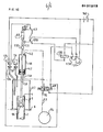
- the distributor head 3 is connected to a device, for example explained in more detail in FIG. 10, which automatically sets it in an upward and downward movement when a predetermined level 45 in the supply vessel 37 is exceeded, as determined by at least one level controller 126.
- the movement of the distributor head 3 is changed in accordance with a further embodiment of the invention in such a way that it is completely lifted out of the pipe 1, so that even the coarsest mechanical impurities can drain through the pipe, which eliminates the blockage.
- FIG. 10 A preferred embodiment of this embodiment of the invention is shown in FIG. 10.
- the two level controllers 126 and 76 are arranged in such a way that they do not respond as long as the liquid level 45 does not rise above the level which arises during operation without clogging. Then all electrical lines of the control system are de-energized and all contacts are in idle status. The contacts of the two microswitches 63 and 128 are closed, the two contacts 136 and 137 of the relay 135 are open and the four-way solenoid valve 70 is in the "OFF" position. In this position, the upper part of the pneumatic cylinder 46 is connected to the compressed air source 74 via line 142, solenoid valve 70 and line 53 and the part below the piston 47 via line 141 to the free atmosphere.
- the circuit: current source 140 ⁇ contact 125 ⁇ microswitch 63 ⁇ 12 ⁇ relay 135 is closed, the latter closing the two contacts 136 and 137.
- the closing of the contact 137 does nothing more than ensure that nothing further happens later. This ensures that the circuit remains closed even when the microswitch 63 is opened.
- the coil 69 of the four-way solenoid valve 70 is excited and this is brought into the "ON" position. In this position, the part of the cylinder 46 located above the piston 47 is connected to the compressed air source 74 via line 141, solenoid valve 70 and line 53.
Landscapes
- Engineering & Computer Science (AREA)
- Physics & Mathematics (AREA)
- Thermal Sciences (AREA)
- Mechanical Engineering (AREA)
- General Engineering & Computer Science (AREA)
- Heat-Exchange Devices With Radiators And Conduit Assemblies (AREA)
- Compression-Type Refrigeration Machines With Reversible Cycles (AREA)
- Separation By Low-Temperature Treatments (AREA)
- Power Steering Mechanism (AREA)
- Physical Or Chemical Processes And Apparatus (AREA)
Priority Applications (1)
| Application Number | Priority Date | Filing Date | Title |
|---|---|---|---|
| AT84107485T ATE29169T1 (de) | 1983-07-06 | 1984-06-28 | Waermeaustauscher. |
Applications Claiming Priority (2)
| Application Number | Priority Date | Filing Date | Title |
|---|---|---|---|
| DE3324330A DE3324330A1 (de) | 1983-07-06 | 1983-07-06 | Waermeuebertrager |
| DE3324330 | 1983-07-06 |
Publications (3)
| Publication Number | Publication Date |
|---|---|
| EP0131213A2 true EP0131213A2 (fr) | 1985-01-16 |
| EP0131213A3 EP0131213A3 (en) | 1985-05-15 |
| EP0131213B1 EP0131213B1 (fr) | 1987-08-26 |
Family
ID=6203286
Family Applications (1)
| Application Number | Title | Priority Date | Filing Date |
|---|---|---|---|
| EP84107485A Expired EP0131213B1 (fr) | 1983-07-06 | 1984-06-28 | Echangeur de chaleur |
Country Status (5)
| Country | Link |
|---|---|
| US (2) | US4799542A (fr) |
| EP (1) | EP0131213B1 (fr) |
| AT (1) | ATE29169T1 (fr) |
| DE (2) | DE3324330A1 (fr) |
| IL (1) | IL72371A (fr) |
Cited By (3)
| Publication number | Priority date | Publication date | Assignee | Title |
|---|---|---|---|---|
| US4799542A (en) * | 1983-07-06 | 1989-01-24 | Hans Sladky | Heat exchanger with thin-film evaporator |
| FR2626191A1 (fr) * | 1988-01-21 | 1989-07-28 | Cezus Co Europ Zirconium | Procede et dispositif d'exploitation d'un appareil fonctionnant par ruissellement d'un film liquide, et application a la separation des tetrachlorures de zr et hf |
| DE4228923A1 (de) * | 1992-08-30 | 1994-03-03 | Sladky Hans | Vorrichtung zur Kühlung von Flüssigkeiten |
Families Citing this family (21)
| Publication number | Priority date | Publication date | Assignee | Title |
|---|---|---|---|---|
| US5291943A (en) * | 1992-12-29 | 1994-03-08 | The Regents Of The University Of California | Heat transfer enhancement using tangential injection |
| WO1998041798A1 (fr) * | 1997-03-17 | 1998-09-24 | Hitachi, Ltd. | Distributeur de liquide, echangeur thermique a couches minces et refrigerateur a absorption |
| US5979440A (en) * | 1997-06-16 | 1999-11-09 | Sequal Technologies, Inc. | Methods and apparatus to generate liquid ambulatory oxygen from an oxygen concentrator |
| US6856778B2 (en) * | 2002-08-15 | 2005-02-15 | Hewlett-Packard Development Company, L.P. | System and method for recycling hydrocarbon-based carrier liquid |
| MY147654A (en) * | 2002-11-13 | 2012-12-31 | Deka Products Lp | Pressurized vapor cycle liquid distillation |
| US7488158B2 (en) * | 2002-11-13 | 2009-02-10 | Deka Products Limited Partnership | Fluid transfer using devices with rotatable housings |
| US8366883B2 (en) * | 2002-11-13 | 2013-02-05 | Deka Products Limited Partnership | Pressurized vapor cycle liquid distillation |
| US8069676B2 (en) | 2002-11-13 | 2011-12-06 | Deka Products Limited Partnership | Water vapor distillation apparatus, method and system |
| MXPA05005245A (es) * | 2002-11-13 | 2005-09-08 | Deka Products Lp | Destilacion con presurizacion de vapor. |
| US8511105B2 (en) | 2002-11-13 | 2013-08-20 | Deka Products Limited Partnership | Water vending apparatus |
| US7597784B2 (en) * | 2002-11-13 | 2009-10-06 | Deka Products Limited Partnership | Pressurized vapor cycle liquid distillation |
| WO2006029457A1 (fr) * | 2004-09-16 | 2006-03-23 | Rheem Australia Pty Limited | Chauffe-eau a recyclage |
| US8291968B2 (en) * | 2005-08-09 | 2012-10-23 | Eestech, Inc. | Distributor for a flowable medium |
| US11826681B2 (en) | 2006-06-30 | 2023-11-28 | Deka Products Limited Partneship | Water vapor distillation apparatus, method and system |
| KR101826492B1 (ko) | 2007-06-07 | 2018-03-22 | 데카 프로덕츠 리미티드 파트너쉽 | 수증기 증류 장치, 방법 및 시스템 |
| US11884555B2 (en) | 2007-06-07 | 2024-01-30 | Deka Products Limited Partnership | Water vapor distillation apparatus, method and system |
| US8359877B2 (en) * | 2008-08-15 | 2013-01-29 | Deka Products Limited Partnership | Water vending apparatus |
| EP2641036A4 (fr) * | 2010-11-16 | 2016-08-17 | Zahid Hussain Ayub | Évaporateur à couche mince |
| US9211482B2 (en) * | 2011-08-19 | 2015-12-15 | Waterpointe—Global, LLC | Methods and apparatus for purifying liquid using regenerating heat exchange |
| WO2014018896A1 (fr) | 2012-07-27 | 2014-01-30 | Deka Products Limited Partnership | Commande de la conductivité dans une sortie d'eau de production destinée à un évaporateur |
| EP3786561B1 (fr) * | 2019-09-02 | 2022-12-14 | Orion Engineered Carbons IP GmbH & Co. KG | Dispositif antisalissure pour échangeurs thermiques et son utilisation |
Family Cites Families (26)
| Publication number | Priority date | Publication date | Assignee | Title |
|---|---|---|---|---|
| DD46722A (fr) * | ||||
| DE46722C (de) * | F. GÄGGEL in Gammertingen | Hemmung, als Sprungwerk dienend | ||
| DE53043C (de) * | 1889-08-23 | 1890-08-09 | J. SCHWAGER in Berlin S.W., Luckenwalderstr. 7 | Oberflächenverdampfer |
| DE65062C (de) * | 1891-12-01 | 1892-10-20 | H. JACOB in Cönnern a. S | Verdampfer |
| GB261731A (en) * | 1925-11-21 | 1927-03-10 | Daniel Guggenheim | Improvements in refrigerating and heat interchanging apparatus |
| DE543710C (de) * | 1927-04-24 | 1932-02-09 | Angel Francisco Ortiz | Regelvorrichtung fuer den Durchlauf von Milch durch Kuehl- und Filtriereinrichtungen |
| DE501093C (de) * | 1929-05-23 | 1930-06-27 | Iwan Kuprianoff | Verfahren zur Erhoehung des Fluessigkeitsumlaufs in Verdampfern von Kaeltemaschinen |
| US1798824A (en) * | 1929-06-12 | 1931-03-31 | White George Hall | Condenser |
| CH166576A (fr) * | 1932-05-23 | 1934-01-15 | Linde Eismasch Ag | Procédé de fabrication d'un mélange gazeux enrichi en oxygène à partir d'air. |
| DE896655C (de) * | 1942-06-14 | 1953-11-12 | Borsig Ag | Turmabsorber, insbesondere fuer Absorptionskaeltemaschinen |
| US2424441A (en) * | 1944-09-06 | 1947-07-22 | Henry Vogt Machine Co | Water distributing ferrule for vertical tube heat exchangers |
| US2462329A (en) * | 1945-01-12 | 1949-02-22 | Harry G Mojonnier | Evaporator having refrigerant recirculation means |
| US2753932A (en) * | 1951-07-30 | 1956-07-10 | Blaw Knox Co | Liquid distributing bell for vertical tubes |
| US2949935A (en) * | 1956-10-29 | 1960-08-23 | Henry Vogt Machine Company | Liquid distributing device |
| AT206864B (de) * | 1958-03-27 | 1959-12-28 | Vogelbusch Gmbh | Gleichstromverdampfer für empfindliche Lösungen |
| AT217990B (de) * | 1958-06-26 | 1961-11-10 | Vogelbusch Gmbh | Vorrichtung zur Regelung der Zufuhr der einzudampfenden Lösung in die Siederohre von Dünnschicht- bzw. Gleichstromverdampfern |
| DE1164990B (de) * | 1960-10-27 | 1964-03-12 | Lorraine Carbone | Kontaktvorrichtung fuer Gase und Fluessigkeiten |
| US3371709A (en) * | 1965-06-15 | 1968-03-05 | Rosenblad Corp | Falling film plate heat exchanger |
| US3524729A (en) * | 1966-11-03 | 1970-08-18 | Schwarza Chemiefaser | Apparatus for continuously polymerizing lactams |
| NL6804152A (fr) * | 1968-03-22 | 1969-09-24 | ||
| FR2096853A1 (en) * | 1970-07-07 | 1972-03-03 | Terrier Andre | Vertical shell and tube evaporator - with improved evaporation and heat transfer |
| US3895674A (en) * | 1972-02-24 | 1975-07-22 | Us Energy | Inlet flow distributor for a heat exchanger |
| IT1009381B (it) * | 1974-03-25 | 1976-12-10 | Sir Soc Italiana Resine Spa | Procedimento per la dissalazione dell acqua di mare e delle acque salmastre |
| CH600279A5 (en) * | 1976-03-12 | 1978-06-15 | Emile Rappaz | Thin falling liquid film heat exchanger |
| US4572287A (en) * | 1983-04-04 | 1986-02-25 | Chicago Bridge & Iron Company | Falling film heat exchanger with film forming members |
| DE3324330A1 (de) * | 1983-07-06 | 1985-01-24 | Hans 2000 Hamburg Sladky | Waermeuebertrager |
-
1983
- 1983-07-06 DE DE3324330A patent/DE3324330A1/de not_active Withdrawn
-
1984
- 1984-06-28 DE DE8484107485T patent/DE3465623D1/de not_active Expired
- 1984-06-28 EP EP84107485A patent/EP0131213B1/fr not_active Expired
- 1984-06-28 AT AT84107485T patent/ATE29169T1/de not_active IP Right Cessation
- 1984-07-11 IL IL72371A patent/IL72371A/xx unknown
-
1986
- 1986-08-04 US US06/892,947 patent/US4799542A/en not_active Expired - Fee Related
-
1989
- 1989-04-10 US US07/249,422 patent/US4848447A/en not_active Expired - Fee Related
Cited By (4)
| Publication number | Priority date | Publication date | Assignee | Title |
|---|---|---|---|---|
| US4799542A (en) * | 1983-07-06 | 1989-01-24 | Hans Sladky | Heat exchanger with thin-film evaporator |
| US4848447A (en) * | 1983-07-06 | 1989-07-18 | Sladky Hans | Tube-type heat exchanger and liquid distributor head therefor |
| FR2626191A1 (fr) * | 1988-01-21 | 1989-07-28 | Cezus Co Europ Zirconium | Procede et dispositif d'exploitation d'un appareil fonctionnant par ruissellement d'un film liquide, et application a la separation des tetrachlorures de zr et hf |
| DE4228923A1 (de) * | 1992-08-30 | 1994-03-03 | Sladky Hans | Vorrichtung zur Kühlung von Flüssigkeiten |
Also Published As
| Publication number | Publication date |
|---|---|
| IL72371A (en) | 1988-09-30 |
| EP0131213A3 (en) | 1985-05-15 |
| DE3465623D1 (en) | 1987-10-01 |
| US4848447A (en) | 1989-07-18 |
| US4799542A (en) | 1989-01-24 |
| EP0131213B1 (fr) | 1987-08-26 |
| ATE29169T1 (de) | 1987-09-15 |
| DE3324330A1 (de) | 1985-01-24 |
Similar Documents
| Publication | Publication Date | Title |
|---|---|---|
| EP0131213A2 (fr) | Echangeur de chaleur | |
| DE1642432B2 (de) | Klaer- und filteranlage | |
| DE69701289T2 (de) | Schleuse für kugeln zur reinigung von kühlsystemen | |
| DE3240186C2 (de) | Vorrichtung zum Reinigen von Tanks | |
| DE3412275C2 (de) | Pulverbeschichtungskabine | |
| DE202008017288U1 (de) | Reinigungsvorrichtung mit Düsenstock für Kühlrohre | |
| DE69106565T2 (de) | Verfahren und Mittel zum Reinigen der Wände von einem Wärmetauscher. | |
| DE202008017291U1 (de) | Reinigungsvorrichtung für Lukos o.dgl. Wärmetauscher | |
| EP0117554B1 (fr) | Pompe à chaleur pour l'extraction de chaleur de l'eau de surface | |
| CH694082A5 (de) | Drahtelektroentladungsbearbeitungsapparat. | |
| DE60217830T2 (de) | Vorrichtung für Wiedergewinnung und Reinigung von Kältemittel einer Klimaanlage | |
| DE1476992A1 (de) | Kuehlsystem | |
| DE3611424C2 (de) | Vorrichtung zur selektierten Zuführung von Reinigungskörpern in Kühlwasser führende Rohre von Wärmetauschern | |
| EP0512288A1 (fr) | Filtre à bande pour séparer des impuretés des bains liquides | |
| DE4021174C2 (de) | Anlage zum Durchlauf-Vakuum-Flüssigbeschichten | |
| DE2919357A1 (de) | Vorrichtung zum herstellen von eiswuerfeln | |
| DE8418505U1 (de) | Waermeaustauscher | |
| DE3028153A1 (de) | Latentwaermespeicher | |
| DE1427912C3 (de) | Einrichtung zum Aufbringen von Kühlflüssigkeit auf ein erhitztes Metallband in einer Walzanlage | |
| DE69501799T2 (de) | Vorrichtung zur Reinigung von Rohren mittels elastischer Kugeln | |
| EP2753186A1 (fr) | Rouleau | |
| DE2729094B2 (de) | Einrichtung zur Gewinnung von kunstlichem Fischrogen aus Lösungen oder Suspensionen von Eiweißstoffen | |
| DE3347815C2 (de) | Reinigungseinrichtung für die Verdampfereinrichtung einer Wärmepumpe zur Entnahme von Wärme aus Wasser | |
| EP1160518A1 (fr) | Humidificateur à évaporation sur une surface | |
| DE1419190A1 (de) | Verfahren und Vorrichtung zur Kondensation von insbesondere chemischen Dampfgemischen |
Legal Events
| Date | Code | Title | Description |
|---|---|---|---|
| PUAI | Public reference made under article 153(3) epc to a published international application that has entered the european phase |
Free format text: ORIGINAL CODE: 0009012 |
|
| AK | Designated contracting states |
Designated state(s): AT BE CH DE FR GB IT LI LU NL SE |
|
| PUAL | Search report despatched |
Free format text: ORIGINAL CODE: 0009013 |
|
| AK | Designated contracting states |
Designated state(s): AT BE CH DE FR GB IT LI LU NL SE |
|
| RAP1 | Party data changed (applicant data changed or rights of an application transferred) |
Owner name: SLADKY, HANS H. |
|
| 17P | Request for examination filed |
Effective date: 19850520 |
|
| GRAA | (expected) grant |
Free format text: ORIGINAL CODE: 0009210 |
|
| AK | Designated contracting states |
Kind code of ref document: B1 Designated state(s): AT BE CH DE FR GB IT LI LU NL SE |
|
| PG25 | Lapsed in a contracting state [announced via postgrant information from national office to epo] |
Ref country code: NL Effective date: 19870826 Ref country code: IT Free format text: LAPSE BECAUSE OF FAILURE TO SUBMIT A TRANSLATION OF THE DESCRIPTION OR TO PAY THE FEE WITHIN THE PRESCRIBED TIME-LIMIT;WARNING: LAPSES OF ITALIAN PATENTS WITH EFFECTIVE DATE BEFORE 2007 MAY HAVE OCCURRED AT ANY TIME BEFORE 2007. THE CORRECT EFFECTIVE DATE MAY BE DIFFERENT FROM THE ONE RECORDED. Effective date: 19870826 Ref country code: FR Free format text: THE PATENT HAS BEEN ANNULLED BY A DECISION OF A NATIONAL AUTHORITY Effective date: 19870826 Ref country code: BE Effective date: 19870826 |
|
| REF | Corresponds to: |
Ref document number: 29169 Country of ref document: AT Date of ref document: 19870915 Kind code of ref document: T |
|
| PG25 | Lapsed in a contracting state [announced via postgrant information from national office to epo] |
Ref country code: SE Effective date: 19870831 |
|
| REF | Corresponds to: |
Ref document number: 3465623 Country of ref document: DE Date of ref document: 19871001 |
|
| EN | Fr: translation not filed | ||
| NLV1 | Nl: lapsed or annulled due to failure to fulfill the requirements of art. 29p and 29m of the patents act | ||
| PLBE | No opposition filed within time limit |
Free format text: ORIGINAL CODE: 0009261 |
|
| STAA | Information on the status of an ep patent application or granted ep patent |
Free format text: STATUS: NO OPPOSITION FILED WITHIN TIME LIMIT |
|
| PG25 | Lapsed in a contracting state [announced via postgrant information from national office to epo] |
Ref country code: LU Free format text: LAPSE BECAUSE OF NON-PAYMENT OF DUE FEES Effective date: 19880630 |
|
| 26N | No opposition filed | ||
| PGFP | Annual fee paid to national office [announced via postgrant information from national office to epo] |
Ref country code: GB Payment date: 19920619 Year of fee payment: 9 |
|
| PGFP | Annual fee paid to national office [announced via postgrant information from national office to epo] |
Ref country code: AT Payment date: 19920630 Year of fee payment: 9 |
|
| PGFP | Annual fee paid to national office [announced via postgrant information from national office to epo] |
Ref country code: DE Payment date: 19921020 Year of fee payment: 9 |
|
| PG25 | Lapsed in a contracting state [announced via postgrant information from national office to epo] |
Ref country code: GB Effective date: 19930628 Ref country code: AT Effective date: 19930628 |
|
| PGFP | Annual fee paid to national office [announced via postgrant information from national office to epo] |
Ref country code: CH Payment date: 19930629 Year of fee payment: 10 |
|
| GBPC | Gb: european patent ceased through non-payment of renewal fee |
Effective date: 19930628 |
|
| PG25 | Lapsed in a contracting state [announced via postgrant information from national office to epo] |
Ref country code: DE Effective date: 19940301 |
|
| PG25 | Lapsed in a contracting state [announced via postgrant information from national office to epo] |
Ref country code: LI Effective date: 19940630 Ref country code: CH Effective date: 19940630 |
|
| REG | Reference to a national code |
Ref country code: CH Ref legal event code: PL |