EP0131218A2 - Relais polarisé électromagnétique avec une disposition de la culasse en forme d'angle - Google Patents
Relais polarisé électromagnétique avec une disposition de la culasse en forme d'angle Download PDFInfo
- Publication number
- EP0131218A2 EP0131218A2 EP84107529A EP84107529A EP0131218A2 EP 0131218 A2 EP0131218 A2 EP 0131218A2 EP 84107529 A EP84107529 A EP 84107529A EP 84107529 A EP84107529 A EP 84107529A EP 0131218 A2 EP0131218 A2 EP 0131218A2
- Authority
- EP
- European Patent Office
- Prior art keywords
- yokes
- spring bracket
- yoke
- relay according
- excitation coil
- Prior art date
- Legal status (The legal status is an assumption and is not a legal conclusion. Google has not performed a legal analysis and makes no representation as to the accuracy of the status listed.)
- Granted
Links
- 230000005284 excitation Effects 0.000 claims description 16
- 230000008901 benefit Effects 0.000 description 4
- 238000004519 manufacturing process Methods 0.000 description 3
- 230000004907 flux Effects 0.000 description 2
- 238000005452 bending Methods 0.000 description 1
- 238000010276 construction Methods 0.000 description 1
- 230000000694 effects Effects 0.000 description 1
- 238000002347 injection Methods 0.000 description 1
- 239000007924 injection Substances 0.000 description 1
- 238000001746 injection moulding Methods 0.000 description 1
- 238000009434 installation Methods 0.000 description 1
- 239000000463 material Substances 0.000 description 1
- 238000000034 method Methods 0.000 description 1
- 230000008569 process Effects 0.000 description 1
- 230000009467 reduction Effects 0.000 description 1
- 238000004904 shortening Methods 0.000 description 1
- 230000007704 transition Effects 0.000 description 1
- 238000004804 winding Methods 0.000 description 1
Images

Classifications
-
- H—ELECTRICITY
- H01—ELECTRIC ELEMENTS
- H01H—ELECTRIC SWITCHES; RELAYS; SELECTORS; EMERGENCY PROTECTIVE DEVICES
- H01H50/00—Details of electromagnetic relays
- H01H50/02—Bases; Casings; Covers
- H01H50/04—Mounting complete relay or separate parts of relay on a base or inside a case
- H01H50/041—Details concerning assembly of relays
- H01H50/042—Different parts are assembled by insertion without extra mounting facilities like screws, in an isolated mounting part, e.g. stack mounting on a coil-support
-
- H—ELECTRICITY
- H01—ELECTRIC ELEMENTS
- H01H—ELECTRIC SWITCHES; RELAYS; SELECTORS; EMERGENCY PROTECTIVE DEVICES
- H01H51/00—Electromagnetic relays
- H01H51/22—Polarised relays
- H01H51/2236—Polarised relays comprising pivotable armature, pivoting at extremity or bending point of armature
- H01H51/2245—Armature inside coil
Definitions
- the invention relates to a polarized, electromagnetic relay with an angled yoke arrangement, consisting of two yokes arranged in parallel at a distance from one another with a permanent magnet arranged between them and lying between armature plates, the legs of this yoke arrangement carrying an excitation coil and the permanent magnet arranged in a pivotable armature rocker with its Anchor plates can be brought into contact with the pole faces of the yokes.
- a relay mentioned at the outset has become known, for example, from DE-C 966 845 or EP-A 1-oo74577. Both embodiments, however, have the disadvantage that the magnetic circuit is unsymmetrical due to the different shape of the L-shaped yokes and therefore relatively large electrical losses occur.
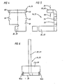
- the invention has set itself the task of developing a polarized, electromagnetic relay of the type mentioned in such a way that the spring bracket serves as a central mounting element for the excitation coil, the yokes and the rocker, thereby eliminating the disadvantages of an asymmetrical magnetic frame caused by other known constructions be that on the one hand all mechanical tolerances and on the other hand all electrical tolerances refer to the central unit of two yoke core parts that are each homogeneous.
- the yokes of the zero point or the K oordinatenursprungJ are the fact that the yokes are in turn each performed in two in itself homogeneous guide grooves, the mechanical tolerances over rocker spring bracket, Steg add, to the contact springs and the electrical tolerances over these two identical parts, air gap, coil former towards the winding).
- the invention is characterized in that all parts are structurally and mechanically related to the spring bracket and locked there, which leads to easy manufacture.
- the spring bracket itself is designed as an inexpensive plastic injection molded part and has the corresponding guide grooves, guide ribs and locking recesses.
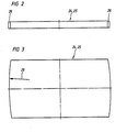
- the symmetry of the magnetic frame is achieved in that the two yokes are L-shaped and exactly symmetrical to one another, that their core legs extend over the entire length of the excitation coil and abut each other in the area of the excitation coil.
- the yokes are designed as cost-effective stamped parts, the manufacture of which does not even have to be carried out with the greatest possible precision, because minor non-parallelities are eliminated by the fact that the yokes are precisely guided in homogeneous, corresponding grooves in the side walls of the spring bracket and this enables precise installation is.
- the parallelism of the pole faces of the yokes is thus achieved solely by the guidance in the area of the grooves in the side walls of the spring bracket, with corresponding guide surfaces being arranged on the yokes. Error radii or errors in the bending surfaces of the entire yoke are always compensated for, even if there should be an air gap within the excitation coil between the core legs of the yokes.
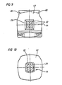
- the armature rocker 11 contains two armature plates 24, 25, which receive the permanent magnets 12 between them. It is important that the end faces of the anchor plate 24, 25 have a radius 26. The radius has the advantage that, despite the exact guidance of the pole faces 27, 28 of the yokes 14, 15, slight anti-parallelism of these faces can still exist due to existing inaccuracies.
- the armature plates 24, 25 close the magnetic circuit from one pole face to the other.
- the anchor plates 24, 25 should lie linearly on the pole faces. However, due to the manufacturing tolerances, this can only be achieved theoretically, and therefore a deliberate transition to a short-line or even punctiform support of the anchor plates 24, 25 on the pole faces 27, 28 is made.
- the contact surfaces 29, 30 of the anchor plates 24, 25 on the pole surfaces 27, 28 are identified in the area of the arrows. The same contact surfaces also apply to the opposite yoke 15.
- the pole faces 27, 28 of the yokes 14, 15 engage in the receiving openings 31, 32 of the rocker 11 formed between the two anchor plates 24, 25.
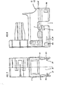
- the latching of the bolt 13 of the rocker 11 in the latching recess 7 on the spring bracket 1 is achieved in that the latching recess 7 is slightly undercut and thereby receives a certain elasticity. Furthermore, the wall of the spring bracket 1 in the area of the guide 6 is weakened with a slot 8.
- each yoke 14, 15 each has a pole face 27, 28 with lower and upper contact surfaces 29, 30, and the yoke also has a yoke plate 33 with lateral latching lugs 16a, 16b.
- the locking lugs 16a, 16b engage in the locking openings 10a, 10b ( Figure 1, Figure 7) of the spring bracket 1.
- the coil body of the excitation coil 17 is inserted into the receiving opening 36 of the spring bracket and locked there in the axial direction by short guide ribs 37, 38.
- the guide ribs 37, 38 engage in corresponding latching openings 39, 40 in accordance with FIG. 9 on the coil flange 42.
- These locking recesses 39, 40 are only on the connection-side coil flange 42, while no locking openings are provided on the opposite coil flange 43. However, they can also be formed on both coil flanges.
- the core legs 22, 23 of the yokes 14, 15 described above then engage in the core opening 44 of the excitation coil 17.
- P for guiding the yoke 14,15 in the region of the yoke bar 33 are each disposed laterally on the yoke plate guide projections 45,46, which engage in associated grooves 47,48 in the spring bracket. This ensures that the yoke plates 33 on the spring bracket 1 are secured in the area of the receiving opening 36.
- grooves 47, 48 extend over the width of the spring bracket. This groove 47, 48 is produced in the plastic injection molding of the spring bracket 1 with a single tool, so that the grooves are exactly parallel due to this tool.
- the spring bracket is universally interchangeable, so that the contacts can be freely selected in the spring bracket.
Landscapes
- Physics & Mathematics (AREA)
- Electromagnetism (AREA)
- Electromagnets (AREA)
- Magnetic Treatment Devices (AREA)
Priority Applications (1)
| Application Number | Priority Date | Filing Date | Title |
|---|---|---|---|
| AT84107529T ATE39305T1 (de) | 1983-07-06 | 1984-06-29 | Polarisiertes, elektromagnetisches relais mit abgewinkelter jochanordnung. |
Applications Claiming Priority (2)
| Application Number | Priority Date | Filing Date | Title |
|---|---|---|---|
| DE3324246 | 1983-07-06 | ||
| DE3324246A DE3324246C2 (de) | 1983-07-06 | 1983-07-06 | Polarisiertes, elektromagnetisches Relais |
Publications (3)
| Publication Number | Publication Date |
|---|---|
| EP0131218A2 true EP0131218A2 (fr) | 1985-01-16 |
| EP0131218A3 EP0131218A3 (en) | 1985-08-21 |
| EP0131218B1 EP0131218B1 (fr) | 1988-12-14 |
Family
ID=6203222
Family Applications (1)
| Application Number | Title | Priority Date | Filing Date |
|---|---|---|---|
| EP84107529A Expired EP0131218B1 (fr) | 1983-07-06 | 1984-06-29 | Relais polarisé électromagnétique avec une disposition de la culasse en forme d'angle |
Country Status (4)
| Country | Link |
|---|---|
| US (1) | US4623863A (fr) |
| EP (1) | EP0131218B1 (fr) |
| AT (1) | ATE39305T1 (fr) |
| DE (2) | DE3324246C2 (fr) |
Cited By (3)
| Publication number | Priority date | Publication date | Assignee | Title |
|---|---|---|---|---|
| DE3837666A1 (de) * | 1988-11-05 | 1990-05-10 | Gruner Kg Relais Fabrik | Relais |
| EP0365518A3 (fr) * | 1988-10-19 | 1991-03-20 | Schrack Elektronik-Aktiengesellschaft | Circuit magnétique constitué essentiellement d'un rectangle plat, présentant un entrefer |
| WO2000024018A1 (fr) * | 1998-10-20 | 2000-04-27 | Releco, S.A. | Relais electromagnetique |
Families Citing this family (3)
| Publication number | Priority date | Publication date | Assignee | Title |
|---|---|---|---|---|
| DE3624783C3 (de) * | 1986-07-22 | 2001-07-05 | Hengstler Gmbh | Relais |
| DE4300594A1 (de) * | 1993-01-13 | 1994-07-14 | Hengstler Bauelemente | Sicherheitsrelais mit zwangsgeführtem Kontaktsatz und monostabilem Antrieb |
| DE202016102110U1 (de) | 2016-04-21 | 2016-07-22 | Johnson Electric Germany GmbH & Co. KG | Aktuator für ein polarisiertes elektromagnetisches Kleinrelais hoher Stromtragefähigkeit |
Family Cites Families (17)
| Publication number | Priority date | Publication date | Assignee | Title |
|---|---|---|---|---|
| BE514133A (fr) * | 1951-09-24 | |||
| NL181144B (nl) | 1953-01-19 | Singer Co | Roterende fluidummeter. | |
| BE541185A (fr) * | 1954-09-09 | |||
| US2825783A (en) * | 1955-07-18 | 1958-03-04 | Raymond T Moloney | Polarized relay |
| US3005071A (en) | 1958-04-30 | 1961-10-17 | Comar Electric Company | Relay structure |
| FR1225043A (fr) * | 1959-02-12 | 1960-06-28 | Perfectionnements aux relais électromagnétiques de petites dimensions pour faiblespuissances | |
| US3167693A (en) | 1961-09-13 | 1965-01-26 | Phillips Eckardt Electronic Co | Electromagnetic relay |
| US3198995A (en) | 1961-10-09 | 1965-08-03 | Allied Control Co | Polarized electromagnetic relay |
| DE1817557C3 (de) * | 1968-12-31 | 1978-10-05 | Gustav Bach Kupfer-Asbest-Co, 7100 Heilbronn | Relais, insbesondere zur Verwendung in gedruckten Schaltungen |
| DE2231525C2 (de) * | 1972-06-28 | 1978-11-30 | Swf-Spezialfabrik Fuer Autozubehoer Gustav Rau Gmbh, 7120 Bietigheim | Kleinrelais, insbesondere für Leiterplatten mit gedruckter Schaltung |
| AT333882B (de) * | 1974-01-25 | 1976-12-10 | Siemens Ag | Relais mit zwei wicklungstragern |
| DE2728509C2 (de) * | 1977-06-23 | 1984-10-31 | Fritz Kuke Kg, 1000 Berlin | Elektromagnetisches Leistungskleinrelais |
| DE2830390C2 (de) * | 1978-07-11 | 1985-01-03 | W. Gruner GmbH & Co Relaisfabrik, KG, 7209 Wehingen | Relais |
| DE7909135U1 (de) * | 1979-03-30 | 1979-07-05 | Siemens Ag, 1000 Berlin Und 8000 Muenchen | Elektromagnetisches Relais für hohe Schaltleistungen |
| JPS5814510A (ja) | 1981-07-20 | 1983-01-27 | Takamisawa Denki Seisakusho:Kk | 電磁石 |
| DE3149816C2 (de) * | 1981-12-16 | 1986-09-04 | Diehl GmbH & Co, 8500 Nürnberg | Polarisiertes Relais |
| DE8301524U1 (fr) * | 1983-01-21 | 1983-04-28 | Eichhoff-Werke Gmbh, 5880 Luedenscheid, De |
-
1983
- 1983-07-06 DE DE3324246A patent/DE3324246C2/de not_active Expired
-
1984
- 1984-06-29 AT AT84107529T patent/ATE39305T1/de not_active IP Right Cessation
- 1984-06-29 DE DE8484107529T patent/DE3475673D1/de not_active Expired
- 1984-06-29 EP EP84107529A patent/EP0131218B1/fr not_active Expired
- 1984-07-02 US US06/626,932 patent/US4623863A/en not_active Expired - Fee Related
Cited By (4)
| Publication number | Priority date | Publication date | Assignee | Title |
|---|---|---|---|---|
| EP0365518A3 (fr) * | 1988-10-19 | 1991-03-20 | Schrack Elektronik-Aktiengesellschaft | Circuit magnétique constitué essentiellement d'un rectangle plat, présentant un entrefer |
| DE3837666A1 (de) * | 1988-11-05 | 1990-05-10 | Gruner Kg Relais Fabrik | Relais |
| WO2000024018A1 (fr) * | 1998-10-20 | 2000-04-27 | Releco, S.A. | Relais electromagnetique |
| US6498552B1 (en) | 1998-10-20 | 2002-12-24 | Santiago Lozano Rico | Electromagnetic relay |
Also Published As
| Publication number | Publication date |
|---|---|
| ATE39305T1 (de) | 1988-12-15 |
| US4623863A (en) | 1986-11-18 |
| DE3324246C2 (de) | 1985-11-28 |
| DE3324246A1 (de) | 1985-01-17 |
| EP0131218A3 (en) | 1985-08-21 |
| DE3475673D1 (en) | 1989-01-19 |
| EP0131218B1 (fr) | 1988-12-14 |
Similar Documents
| Publication | Publication Date | Title |
|---|---|---|
| EP0594031B1 (fr) | Elément électrique d'inductance | |
| DE3526852A1 (de) | Magnetschaltkreisvorrichtung | |
| DE2816555A1 (de) | Magnetkreisanordnung fuer einen elektromagneten fuer einen mit einem permanentmagneten als anker | |
| DE3843359A1 (de) | Elektromagnetisches relais | |
| EP0147681B1 (fr) | Relais électromagnétique polarisé | |
| EP0131218A2 (fr) | Relais polarisé électromagnétique avec une disposition de la culasse en forme d'angle | |
| DE1909940B2 (de) | Elektromagnetisches umschaltrelais mit geschuetztem kontakt system | |
| DE3047608C2 (de) | Elektromagnetisches Relais | |
| DE3783834T2 (de) | Elektromagnetisches relais. | |
| EP0252344B1 (fr) | Relais électromagnétique | |
| EP0091687B1 (fr) | Relais électromagnétique | |
| DE3002899C2 (de) | Tonabnehmersystem mit beweglicher Spule | |
| EP0198492B1 (fr) | Relais électromagnétique polarisé | |
| DE1764921C3 (de) | Magnetsystem für einen Relaisschalter | |
| DE3340904A1 (de) | Magnetisch betaetigte schaltanordnung, insbesondere luftschuetz | |
| DE10261473B4 (de) | Elektromagnetisches Relais | |
| DE2420034A1 (de) | Elektromagnetisches schaltgeraet | |
| EP0226891A1 (fr) | Méthode de fabrication d'un relais électromagnétique sans réglage | |
| DE2647203A1 (de) | Elektromagnetisches miniaturrelais | |
| DE1934624B2 (de) | Elektromagnetisches Relais | |
| AT402581B (de) | Gepoltes elektromagnetisches relais | |
| DE2402236C3 (de) | Steckbares, mit einem quaderförmigen Gehäuse versehenes, elektromagnetisches Relais | |
| EP0172384B1 (fr) | Dispositif électromagnétique pour la commande d'un noyau plongeur | |
| DE2523254C3 (de) | Einrichtung zur Halterung eines Spulenkörpers auf einem Eisenkern | |
| AT217543B (de) | Elektromagnetisches Schaltschütz, insbesondere für Wechselstrom |
Legal Events
| Date | Code | Title | Description |
|---|---|---|---|
| PUAI | Public reference made under article 153(3) epc to a published international application that has entered the european phase |
Free format text: ORIGINAL CODE: 0009012 |
|
| AK | Designated contracting states |
Designated state(s): AT BE CH DE FR GB IT LI LU NL SE |
|
| PUAL | Search report despatched |
Free format text: ORIGINAL CODE: 0009013 |
|
| AK | Designated contracting states |
Designated state(s): AT BE CH DE FR GB IT LI LU NL SE |
|
| 17P | Request for examination filed |
Effective date: 19860125 |
|
| 17Q | First examination report despatched |
Effective date: 19861107 |
|
| GRAA | (expected) grant |
Free format text: ORIGINAL CODE: 0009210 |
|
| AK | Designated contracting states |
Kind code of ref document: B1 Designated state(s): AT BE CH DE FR GB IT LI LU NL SE |
|
| PG25 | Lapsed in a contracting state [announced via postgrant information from national office to epo] |
Ref country code: NL Effective date: 19881214 Ref country code: BE Effective date: 19881214 |
|
| REF | Corresponds to: |
Ref document number: 39305 Country of ref document: AT Date of ref document: 19881215 Kind code of ref document: T |
|
| ITF | It: translation for a ep patent filed | ||
| REF | Corresponds to: |
Ref document number: 3475673 Country of ref document: DE Date of ref document: 19890119 |
|
| ET | Fr: translation filed | ||
| GBT | Gb: translation of ep patent filed (gb section 77(6)(a)/1977) | ||
| NLV1 | Nl: lapsed or annulled due to failure to fulfill the requirements of art. 29p and 29m of the patents act | ||
| ITTA | It: last paid annual fee | ||
| PG25 | Lapsed in a contracting state [announced via postgrant information from national office to epo] |
Ref country code: LU Free format text: LAPSE BECAUSE OF NON-PAYMENT OF DUE FEES Effective date: 19890630 |
|
| PLBE | No opposition filed within time limit |
Free format text: ORIGINAL CODE: 0009261 |
|
| STAA | Information on the status of an ep patent application or granted ep patent |
Free format text: STATUS: NO OPPOSITION FILED WITHIN TIME LIMIT |
|
| 26N | No opposition filed | ||
| PGFP | Annual fee paid to national office [announced via postgrant information from national office to epo] |
Ref country code: AT Payment date: 19900615 Year of fee payment: 7 |
|
| PGFP | Annual fee paid to national office [announced via postgrant information from national office to epo] |
Ref country code: GB Payment date: 19900625 Year of fee payment: 7 |
|
| PGFP | Annual fee paid to national office [announced via postgrant information from national office to epo] |
Ref country code: FR Payment date: 19900626 Year of fee payment: 7 |
|
| PGFP | Annual fee paid to national office [announced via postgrant information from national office to epo] |
Ref country code: SE Payment date: 19900628 Year of fee payment: 7 |
|
| PGFP | Annual fee paid to national office [announced via postgrant information from national office to epo] |
Ref country code: DE Payment date: 19900630 Year of fee payment: 7 |
|
| PGFP | Annual fee paid to national office [announced via postgrant information from national office to epo] |
Ref country code: CH Payment date: 19900831 Year of fee payment: 7 |
|
| PG25 | Lapsed in a contracting state [announced via postgrant information from national office to epo] |
Ref country code: GB Effective date: 19910629 Ref country code: AT Effective date: 19910629 |
|
| PG25 | Lapsed in a contracting state [announced via postgrant information from national office to epo] |
Ref country code: SE Effective date: 19910630 Ref country code: LI Effective date: 19910630 Ref country code: CH Effective date: 19910630 |
|
| GBPC | Gb: european patent ceased through non-payment of renewal fee | ||
| PG25 | Lapsed in a contracting state [announced via postgrant information from national office to epo] |
Ref country code: FR Effective date: 19920228 |
|
| REG | Reference to a national code |
Ref country code: CH Ref legal event code: PL |
|
| PG25 | Lapsed in a contracting state [announced via postgrant information from national office to epo] |
Ref country code: DE Effective date: 19920401 |
|
| REG | Reference to a national code |
Ref country code: FR Ref legal event code: ST |
|
| EUG | Se: european patent has lapsed |
Ref document number: 84107529.4 Effective date: 19920109 |