EP0131236A1 - Installation mécanique et biologique et procédé pour l'épuration d'eaux usées - Google Patents
Installation mécanique et biologique et procédé pour l'épuration d'eaux usées Download PDFInfo
- Publication number
- EP0131236A1 EP0131236A1 EP19840107691 EP84107691A EP0131236A1 EP 0131236 A1 EP0131236 A1 EP 0131236A1 EP 19840107691 EP19840107691 EP 19840107691 EP 84107691 A EP84107691 A EP 84107691A EP 0131236 A1 EP0131236 A1 EP 0131236A1
- Authority
- EP
- European Patent Office
- Prior art keywords
- outer tube
- treatment plant
- plant according
- wastewater
- immersion body
- Prior art date
- Legal status (The legal status is an assumption and is not a legal conclusion. Google has not performed a legal analysis and makes no representation as to the accuracy of the status listed.)
- Granted
Links
- 239000002351 wastewater Substances 0.000 title claims description 53
- 238000000034 method Methods 0.000 title claims description 5
- 230000008569 process Effects 0.000 title claims description 3
- 238000000746 purification Methods 0.000 title description 3
- 238000009434 installation Methods 0.000 title 1
- 238000007654 immersion Methods 0.000 claims abstract description 70
- 239000010865 sewage Substances 0.000 claims abstract description 22
- 239000000203 mixture Substances 0.000 claims abstract description 16
- 239000002184 metal Substances 0.000 claims abstract description 14
- XLYOFNOQVPJJNP-UHFFFAOYSA-N water Substances O XLYOFNOQVPJJNP-UHFFFAOYSA-N 0.000 claims abstract description 9
- 238000012856 packing Methods 0.000 claims description 19
- 238000004065 wastewater treatment Methods 0.000 claims description 9
- 239000000945 filler Substances 0.000 claims description 8
- 238000005352 clarification Methods 0.000 claims description 5
- 239000013590 bulk material Substances 0.000 claims description 4
- 238000004140 cleaning Methods 0.000 claims description 3
- 239000000463 material Substances 0.000 abstract description 2
- 229910052760 oxygen Inorganic materials 0.000 description 11
- 239000001301 oxygen Substances 0.000 description 11
- QVGXLLKOCUKJST-UHFFFAOYSA-N atomic oxygen Chemical compound [O] QVGXLLKOCUKJST-UHFFFAOYSA-N 0.000 description 10
- 238000006065 biodegradation reaction Methods 0.000 description 9
- 238000010276 construction Methods 0.000 description 9
- 230000000694 effects Effects 0.000 description 7
- 230000002093 peripheral effect Effects 0.000 description 7
- 230000033001 locomotion Effects 0.000 description 6
- 210000002105 tongue Anatomy 0.000 description 6
- 230000008901 benefit Effects 0.000 description 5
- 230000015556 catabolic process Effects 0.000 description 4
- 238000006731 degradation reaction Methods 0.000 description 4
- 238000013461 design Methods 0.000 description 3
- 238000010586 diagram Methods 0.000 description 3
- 239000010801 sewage sludge Substances 0.000 description 3
- 239000010802 sludge Substances 0.000 description 3
- 230000009471 action Effects 0.000 description 2
- 238000005276 aerator Methods 0.000 description 2
- 238000011161 development Methods 0.000 description 2
- 238000004519 manufacturing process Methods 0.000 description 2
- 238000006213 oxygenation reaction Methods 0.000 description 2
- 238000009423 ventilation Methods 0.000 description 2
- 239000002028 Biomass Substances 0.000 description 1
- 238000001994 activation Methods 0.000 description 1
- 230000009286 beneficial effect Effects 0.000 description 1
- 230000031018 biological processes and functions Effects 0.000 description 1
- 230000015572 biosynthetic process Effects 0.000 description 1
- 230000003247 decreasing effect Effects 0.000 description 1
- 230000001419 dependent effect Effects 0.000 description 1
- 238000007598 dipping method Methods 0.000 description 1
- 238000005265 energy consumption Methods 0.000 description 1
- 230000006872 improvement Effects 0.000 description 1
- 238000005259 measurement Methods 0.000 description 1
- 239000007769 metal material Substances 0.000 description 1
- 238000012986 modification Methods 0.000 description 1
- 230000004048 modification Effects 0.000 description 1
- 235000015097 nutrients Nutrition 0.000 description 1
- 238000005192 partition Methods 0.000 description 1
- 238000005086 pumping Methods 0.000 description 1
- 238000004080 punching Methods 0.000 description 1
- 238000007493 shaping process Methods 0.000 description 1
- 238000012360 testing method Methods 0.000 description 1
Images



Classifications
-
- C—CHEMISTRY; METALLURGY
- C02—TREATMENT OF WATER, WASTE WATER, SEWAGE, OR SLUDGE
- C02F—TREATMENT OF WATER, WASTE WATER, SEWAGE, OR SLUDGE
- C02F3/00—Biological treatment of water, waste water, or sewage
- C02F3/02—Aerobic processes
- C02F3/08—Aerobic processes using moving contact bodies
- C02F3/082—Rotating biological contactors
-
- Y—GENERAL TAGGING OF NEW TECHNOLOGICAL DEVELOPMENTS; GENERAL TAGGING OF CROSS-SECTIONAL TECHNOLOGIES SPANNING OVER SEVERAL SECTIONS OF THE IPC; TECHNICAL SUBJECTS COVERED BY FORMER USPC CROSS-REFERENCE ART COLLECTIONS [XRACs] AND DIGESTS
- Y02—TECHNOLOGIES OR APPLICATIONS FOR MITIGATION OR ADAPTATION AGAINST CLIMATE CHANGE
- Y02W—CLIMATE CHANGE MITIGATION TECHNOLOGIES RELATED TO WASTEWATER TREATMENT OR WASTE MANAGEMENT
- Y02W10/00—Technologies for wastewater treatment
- Y02W10/10—Biological treatment of water, waste water, or sewage
Definitions
- the invention relates to a mechanical-biological sewage treatment plant for the purification of waste water, with a rotating immersion body immersed in the waste water, which has a perforated outer tube and is filled with bulk material as a fouling element for biological turf. It also relates to a method for treating waste water using this device.
- Sewage treatment plants with such immersion bodies are known. However, they have not been used for a long time since the bulk material silted up disproportionately quickly, whereupon the plant changed from aerobic to anaerobic sludge degradation. However, this must not happen in a good sewage treatment plant.
- the CH-PS 50 963 shows an immersion body, which coaxially has a drivable shaft and at a distance from it a perforated outer and a perforated inner tube. The space between the two pipes is filled with bulk material, which serves as a growth element for the organic lawn.
- This known immersion body rotates about a third immersed in the wastewater. In the submerged state, the biological lawn saturates with atmospheric oxygen and, when submerged, enters it into the wastewater. The assembly of such immersion bodies on site is difficult. They also silt up slightly and the wastewater begins to stink.
- a further immersion body which is formed from a plurality of ring, sector or cube-shaped partial bodies which are arranged in a ring in a row around the coaxial, driven shaft.
- each part of the body there is a stack of individual plastic plates, which are placed on one another in layers and have, for example, a wavy surface.
- the plates serve as vegetation bodies for the organic lawn.
- the plates are arranged perpendicular to the shaft, so that when they emerge from the waste water, the waste water residues can run off quickly from the plate surface. Only about a third of its diameter is submerged in the wastewater.
- a further device for mechanical-biological purification of waste water is known from DE-AS 11 84 286.
- This is about a horizontally rotatable loading drum ventilation t being filled with special filling bodies is.
- the -u cleaning wastewater is introduced at one end of the drum and with the help of a spiral pipe surfaces promoted to the other end of the drum.
- the fillers which completely fill the interior of the drum, for example, have the shape of scoops. They therefore take up a certain amount of waste water and transport it upwards, where it is poured out and slowly trickles down through the drum. It comes into intimate contact with the organic lawn that has formed on the packing. In this type of wastewater treatment plant, too, a large part of the biologically active surface is not involved in the wastewater treatment.
- drum-shaped immersion bodies is known from DE-OS 26 38 665 or 27 27 991.
- These published documents show, among other things, an immersion body with a central, driven axis, on which a sectioned tube is attached.
- the inside of the immersion body is divided into chambers with the help of curved, unperforated bulkheads.
- stacks of superimposed plastic plates with a suitably designed surface serve as vegetation bodies for the organic turf. Only about a third of this immersion body is immersed in the wastewater.
- the section-wise perforation of the outer pipe and the design and arrangement of the bulkhead walls are coordinated so that a certain amount of air is taken under water when the chambers are immersed in the waste water. This air begins to flow out through the perforations in the outer tube as soon as the chamber has passed its lowest position. This does indeed result in a certain oxygen enrichment of the wastewater in the clarifier itself; however, the part of the vegetation dipping into the air bubble takes part in the sewage drain Do not take part until the air has escaped from the chamber. For this reason, the biological degradation performance of a sewage treatment plant with such an immersion body is not higher than that of the plants described above.
- the immersion body consists of a central hollow shaft on which a polygonal drum made of sheet metal plates is fastened by means of bulkheads, so that a inside the drum Series of chambers are formed. These chambers are filled with plastic plates with a suitable surface that are stacked on top of one another. Slots in the outer drum are arranged so that when a chamber is immersed in the waste water, a larger amount of air is taken along. With the help of additional partition walls, it is ensured that this air is circulated within the chamber.
- the hollow shaft is equipped with individual openings, so that the air enclosed in the chambers can flow from the lower chambers into the hollow shaft and from the hollow shaft into the upper chambers.
- the part of the fouling element which currently projects into the air bubble does not take part in the wastewater treatment; however, since the air can also flow through the hollow shaft here, the degradation performance is slightly better than in the system described above.
- DE-OS 31 09 184 shows a modification of the system just described.
- additional chambers are arranged on the outside of the polygonal drum, in which additional air volumes below the waste water level can be taken.
- the air enclosed in these additional chambers can partially flow into the waste water after the bottom dead center has been exceeded.
- this air does not come into contact with the plate-shaped growth bodies, there is practically no measurable improvement in the biodegradation performance.
- the sub-bodies of these immersion bodies are either completely immersed in the wastewater or completely immersed in the wastewater, air being introduced into the wastewater again here by appropriate partial perforation of the outer skin.
- These mainly used embodiments of immersion bodies are also shown in DE-OS 26 38 665 and 27 27 991 in addition to the embodiments described above.
- the present invention has for its object to provide a mechanical-biological sewage treatment plant of the type described above, which can be used with the simplest mechanical design for small and large plants, which enables the entry of oxygen and kinetic energy into the wastewater with improved efficiency and thereby increased Clarification effect or greater resilience enables.
- an inner tube is arranged concentrically with the outer tube, that the inner tube and outer tube are connected to one another and with axle journals via end plates, that the outer tube is profiled on its outside in such a way that an intimately swirled wastewater / air mixture when the immersion body rotates arises in the clarifier, and that the immersion body is filled with packing elements which have a large inner surface and whose contours are designed in such a way that the wastewater-air mixture can flow between the packing elements.
- outer tube is intended to make it clear that this tube is the space in which the filling bodies carrying the organic turf are located, i.e. limited against the clarifier.
- the additional arrangement of an inner tube limits the space available to the packing, e.g. then, if a biodegradation due to lack of oxygen is not to be expected in the center of the rotor.
- a major advantage of the construction according to the invention is the high stability of the immersion body. If Probably both the tubes and the end plates consist only of relatively thin-walled plates, which may also be broken, the rotating immersion body can easily be up to 10 m long without any strength problems.
- a so-called blade tube can be provided concentrically with the outer tube.
- This blade tube supports the introduction of air and movement into the wastewater and has the advantage of simpler manufacture compared to the attachment of individual, turbine-like blades on the outside of the outer tube.
- the present invention largely avoids the work phases to be distinguished in the previous sewage treatment plants: ascent phase for oxygen enrichment and immersion phase for biodegradation. Rather, the rotating immersion body creates an intimately swirled wastewater-air mixture in the clarifier, so that the biological lawn growing on the packing elements is constantly in a medium that enables both oxygenation and biodegradation. This results in the possibility of keeping the fillers of the immersion body almost constantly below the water level in the clarifier. This means that the immersion body can remain completely submerged. In practice, part of the immersion body space remains above the water level, since it has been shown that the immersion bodies take considerable amounts of air with them.
- the immersion body In order to generate the swirled wastewater-air mixture, the immersion body must rotate at a considerably higher speed than the immersion bodies currently used. This At the same time, it gives the option of introducing increased kinetic energy into the wastewater, thereby preventing sewage sludge from settling even in large pools and increasing the dwell time of the wastewater, which in turn is beneficial for the increased clarification effect and the increased load capacity of the system.
- the fillers preferably have a spherical shape with a series of webs which are separated from one another by gaps, the shape and dimensions being selected such that adjacent fillers do not get caught in one another, but on the other hand the wastewater / air mixture has perfect access to the organic lawn.
- the outer tube can be equipped with blades similar to turbine blades.
- the perforations in the outer tube are designed as elongated holes and the sheet metal parts punched out of the elongated holes are bent out in an S shape over the contour of the outer tube in the direction of rotation of the immersion body.
- the inner tube is filled with air. In this way, it generates a buoyancy that not only compensates for the weight of the inner tube itself but also for part of the weight of the rest of the construction.
- the size of this buoyancy depends on the diameter of the inner tube, whereby a compromise must be found between the size of the buoyancy and the size of the space between the inner tube and the outer tube still available for the packing.
- the special thing about the treatment process using the sewage treatment plant according to the invention is the high production speed on the circumference of the outer tube or, if necessary, the shovel tube, which is so high that an intimately swirled and mixed wastewater-air mixture is created in the clarifier, in which the biological lawn-bearing vegetation bodies are constantly moved. Due to this special feature, the space of the immersion body filled with vegetation bodies can practically rotate completely below the water line. If the space filled with fouling bodies is at least partially exposed, the fouling bodies themselves serve as scoop elements which also carry a considerable amount of atmospheric oxygen into the waste water. Experience shows that long after turning off the shoot movement Air bubbles rise out of the vegetation. Even if this bubble formation has come to rest, the growth bodies still contain considerable amounts of air, which also bubbles out when the T is turned gently. However, as long as both wastewater and air are available to the organic lawn, the sewage sludge is broken down.
- Axle journals 4 run in the bearings 3, which establish the connection to the actual immersion body, which consists of a perforated inner tube 9 and a perforated outer tube 10, which are connected to one another and to the axle journals 4 via end plates 8 on the end faces.
- a drive pulley 5 is mounted on the left axle pin 4, on which a drive means 6, for example a chain, runs, which transmits the drive energy of a geared motor 7 to the axle pin 4 and thus to the immersion body 8, 9, 10.
- the inner tube 9 consists of sheet metal, which has been given a lattice shape by punching. This ensures an optimal passage of wastewater or wastewater / air mixture.
- the outer tube 10 is provided with a regular arrangement of elongated holes 11.
- the sheet metal material punched out of the elongated holes is bent out in an S-shape over the outer contour of the outer tube 10, as can be seen better in FIG. 2.
- These S-shaped metal tongues 12 form blades which set the waste water in motion, which prevents settling of sewage sludge at the bottom of the basin 2, and contribute to the discharge appropriate speed air-oxygen in the waste water.
- the immersion body dips into the wastewater to such an extent that the outer tube 10, which is filled with packing elements, rotates almost completely in the wastewater.
- the distinction between the immersion phase and the immersion phase, which was customary up to now, can be dispensed with.
- the tests carried out have shown that the water level where the immersion body emerges from the waste water rises higher than in the rest of the pool.
- the special shape of the immersion body and the centrifugal force create a flow that pumps air and wastewater axially out of the pool into the immersion body and thus to the packing elements or to the biological lawn.
- FIG. 2 shows a cross section through a further embodiment of an immersion body, different variants for the design of the individual parts of the immersion body being shown in the individual quadrants.
- An unperforated inner tube 9 can be seen first, concentrically with the perforated outer tube 10 and again concentrically with this also a perforated blade tube 22.
- the inner tube 9 is filled with air. Since the inner tube 9 is constantly immersed in the wastewater, it provides additional buoyancy, which not only compensates for the weight of the inner tube 9 itself, but also for part of the weight of the rest of the construction. This relieves the load on the bearings and saves drive energy.
- Outer tube 10 and possibly blade tube 22 can be profiled in a wide variety of ways. Shown are, for example, S-shaped sheet metal tongues 12 bent out of the elongated holes 11 or also S-shaped sheet metal tongues 12 ', which are partly outside, partly inside the outer contour of the tubes 10, 22.
- the perforations of the tubes 10, 22 can also be designed differently.
- the perforations 11 are somewhat larger than the standing metal webs, the perforations 11 'are considerably larger than the standing metal webs and the perforations 11 "are as large as the metal webs.
- a suction or nozzle effect on the elongated holes arises, the air sucks under the water surface and divides it into the finest bubbles, and that this effect is considerably enhanced by the tongues 12, 12 '.
- the combined action of the outer contour of the immersion body and the centrifugal force creates a flow in the clarifier which pumps the waste water axially into the immersion body and radially out of the immersion body.
- 8 openings for example radial slots 21, are provided in the end plates.
- the size of the slots 21 and also the size of the perforations 11 in the outer tube 10 is to be matched to the size of the immersion bodies so that they cannot leave the space 13 between the inner tube 9 and the outer tube 10.
- the centrifugal force can be changed considerably - increased or decreased - by installing radial bulkheads 16, 16 ', 16 ".
- These bulkheads 16, 16', 16" which simultaneously divide the interior 13 into chambers, act in conjunction with the relative high peripheral speed of the immersion body like the wings of a centrifugal pump. This effect can be strengthened or weakened by suitable shaping of the bulkheads 16.
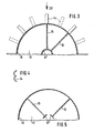
- FIG. 3 also shows in cross section a further embodiment for an immersion body with an inner tube 9 'and an outer tube 10.
- the space 13 between the two tubes is partitioned off with the aid of bulkheads 15, 16, the bulkheads 15 being perforated, the bulkheads 16 being unperforated .
- Blades 14 are attached to the outer tube, the cross section of which corresponds, for example, to the cross section of Pelton turbines, as shown in FIG. 4.
- These blades 14, either alone or in addition to the S-shaped tongues 12 featured air and kinetic energy can be seen in the wastewater. Instead of the blades 14, which must be attached individually, there is also the possibility of providing an additional tube as a blade tube for ventilation and movement.
- the bulkheads 15, 16 not only limit the movement space for the fillers, but at the same time stiffen the overall construction of the immersion body, which is particularly advantageous when the tubes 9 ', 10 are very long and have a small outside diameter.
- the inner tube 9 is designed as a polygonal sheet metal cylinder with continuous longitudinal slots. To form the longitudinal slots, the metal sheets of the inner tube 9" were not welded to one another or only at points. They are held by the bulkheads 15, 16 on the outer tube 10.
- the outer tube 10 can, as already described with reference to FIGS. 1 to 4, be equipped with blades 14 as well as with S-shaped tongues 12, 12 '. A blade tube 22 is also possible.
- Fig. 6 shows a graph in which in a rectangular coordinate system on the X axis, the speed V on the circumference of the outer tube 10 in m / s and on the Y axis, the specific biodegradation rate kg BOD 5 per kWh or the specific Oxygenation in kg 0 2 are also shown per kWh.
- the peripheral speed V increases, the specific oxygen input into the wastewater increases.
- the peripheral speed is currently on the market widespread immersion body specified, which corresponds approximately to the subject of DE-OS 27 27 991, while the surface aerators currently in use with a peripheral speed of 2.5 m / sec. work.
- the specific degradation capacity was entered in the diagram according to parameters, namely with 0.6 or 1.0 kg BOD 5 / kWh.
- the value of 1.0 kg BOD S / kWh corresponds to the system just mentioned according to DE-OS 27 27 991; the value 0.6 corresponds to the known activation processes with horizontal-axis surface aerators. These are mean values from various measurements. It is clear that the specific biodegradation power cannot be increased linearly with the drive power for the immersion body, since this is a biological process which is essentially dependent on the supply of oxygen on the one hand and nutrients, ie waste water on the other hand.
- the diagram shows that an optimal speed range V o p t is between 0.9 and 1.6 m / s.
- An optimal wastewater-air mixture can be used at peripheral speeds of up to 5 m / sec. to reach.
- the peripheral speed of the immersion body according to the invention is thus five to ten times higher than that of the currently customary immersion bodies.
- Fig. 7 shows a cross section through a filler 17, preferably made of plastic.
- a filler 17 preferably made of plastic.
- the diameter of such a packing 17 is approximately 5 cm.
- the width of the webs 18 must at least be greater than the width of the interstices 19 at least on the spherical surface and only partially there.
- a major advantage of the invention in addition to the already mentioned increased biodegradation capacity is that the immersion body drum can be built in practically any length. Spans between the bearings of five to ten meters are conceivable. This is possible by dispensing with a continuous central axis, on which the other construction is attached.
- the selected construction of tube and inner tube enables the deflection between the axle bearings to be limited to a reasonable value by appropriate choice of sheet thickness and tube diameter, whereby these values can be increased even further by using an air-filled inner tube.
Landscapes
- Life Sciences & Earth Sciences (AREA)
- Health & Medical Sciences (AREA)
- Molecular Biology (AREA)
- Biodiversity & Conservation Biology (AREA)
- Microbiology (AREA)
- Hydrology & Water Resources (AREA)
- Engineering & Computer Science (AREA)
- Environmental & Geological Engineering (AREA)
- Water Supply & Treatment (AREA)
- Chemical & Material Sciences (AREA)
- Organic Chemistry (AREA)
- Biological Treatment Of Waste Water (AREA)
Priority Applications (1)
| Application Number | Priority Date | Filing Date | Title |
|---|---|---|---|
| AT84107691T ATE25373T1 (de) | 1983-07-09 | 1984-07-03 | Mechanisch-biologische klaeranlage zum reinigen von abwaessern sowie verfahren zum klaeren von abwaessern. |
Applications Claiming Priority (2)
| Application Number | Priority Date | Filing Date | Title |
|---|---|---|---|
| DE3324853 | 1983-07-09 | ||
| DE19833324853 DE3324853A1 (de) | 1983-07-09 | 1983-07-09 | Mechanisch-biologische klaeranlage zum reinigen von abwaessern |
Publications (2)
| Publication Number | Publication Date |
|---|---|
| EP0131236A1 true EP0131236A1 (fr) | 1985-01-16 |
| EP0131236B1 EP0131236B1 (fr) | 1987-02-04 |
Family
ID=6203608
Family Applications (1)
| Application Number | Title | Priority Date | Filing Date |
|---|---|---|---|
| EP19840107691 Expired EP0131236B1 (fr) | 1983-07-09 | 1984-07-03 | Installation mécanique et biologique et procédé pour l'épuration d'eaux usées |
Country Status (5)
| Country | Link |
|---|---|
| US (1) | US4540491A (fr) |
| EP (1) | EP0131236B1 (fr) |
| JP (1) | JPS6038090A (fr) |
| AT (1) | ATE25373T1 (fr) |
| DE (1) | DE3324853A1 (fr) |
Cited By (3)
| Publication number | Priority date | Publication date | Assignee | Title |
|---|---|---|---|---|
| EP0196338A1 (fr) * | 1983-11-16 | 1986-10-08 | Walker Process Corporation | Appareil pour le traitement d'eau |
| EP0387241A3 (fr) * | 1989-03-08 | 1992-05-20 | Franz Dipl.-Ing.Dr.Techn. Kühtreiber | Procédé et dispositif pour l'introduction de gaz dans des liquides |
| DE102016109802A1 (de) | 2016-05-27 | 2017-11-30 | Gottfried Wilhelm Leibniz Universität Hannover | Anordnung zur Behandlung von Wässern mit mindestens zwei Tauchkörpern und Verfahren zur Behandlung von Wässern hiermit |
Families Citing this family (21)
| Publication number | Priority date | Publication date | Assignee | Title |
|---|---|---|---|---|
| DE3513602C2 (de) * | 1985-04-16 | 1987-04-30 | Grabowski Tropfkörper-Technik GmbH, 6352 Ober-Mörlen | Hohlkörper zur biologischen Abwasserreinigung |
| US4668387A (en) * | 1985-09-23 | 1987-05-26 | Envirex Inc. | Deep submergence rotating biological contactor apparatus |
| KR900002339B1 (ko) * | 1987-01-30 | 1990-04-12 | 최승휘 | 회전 경사 접촉판 폐수처리 장치 |
| DE8809767U1 (de) * | 1988-08-01 | 1988-11-10 | Kernforschungsanlage Jülich GmbH, 5170 Jülich | Allgemein horizontaler Drehrohrreaktor mit Schüttkörperbett für biotechnologische Prozesse |
| DE4203103A1 (de) * | 1992-02-04 | 1993-08-05 | Passavant Werke | Einrichtung fuer die biologische reinigung von abwasser |
| US5256570A (en) * | 1992-10-20 | 1993-10-26 | Clyde Robert A | Bioreactor configured for various permeable cell supports and culture media |
| US5326459A (en) * | 1992-11-12 | 1994-07-05 | Envirex Inc. | Wastewater treatment apparatus |
| US5401398A (en) * | 1993-06-01 | 1995-03-28 | Geo-Form, Inc. | Media for rotating biological contactor |
| US5350507A (en) * | 1993-06-01 | 1994-09-27 | Geo-Form, Inc. | Contact device and container for a rotating biological contactor |
| US5556765A (en) * | 1994-02-18 | 1996-09-17 | Dedolph; Richard R. | Reactor using tubular spiroids for gas/liquid propulsion |
| US7491324B2 (en) * | 2002-07-11 | 2009-02-17 | Ionic Water Technologies, Inc. | Rotating perforated cylinder treatment system |
| US7011745B1 (en) * | 2002-07-11 | 2006-03-14 | Moulton Patrick L | Rotating perforated cylinder treatment system |
| US6949191B1 (en) | 2004-04-29 | 2005-09-27 | Jrj Holdings, Llc | Packaged wastewater treatment unit |
| US20080261299A1 (en) * | 2007-04-23 | 2008-10-23 | Zeikus J Gregory | Pneumatic Bioreactor |
| US7628528B2 (en) * | 2005-10-26 | 2009-12-08 | PRS Biotech, Inc. | Pneumatic bioreactor |
| US8790913B2 (en) * | 2005-10-26 | 2014-07-29 | Pbs Biotech, Inc. | Methods of using pneumatic bioreactors |
| US7713730B2 (en) | 2007-04-24 | 2010-05-11 | Pbs Biotech, Inc. | Pneumatic bioreactor |
| EP2279240A2 (fr) * | 2008-04-25 | 2011-02-02 | PBS Biotech, Inc | Appareil de bioréacteur |
| ITMI20131257A1 (it) * | 2013-07-26 | 2015-01-27 | Eco Sistemi S R L | Apparato per la depurazione di acque impure, in particolare di acque reflue e/o inquinate |
| DE102020115342A1 (de) * | 2020-06-09 | 2021-12-09 | Jürgen Berthold | Walzenbaugruppe, insbesondere zur Wasseraufbearbeitung, und Aufbereitungsvorrichtung |
| US11702353B2 (en) * | 2021-01-19 | 2023-07-18 | Christopher A. Limcaco | Floating water treatment apparatus |
Citations (7)
| Publication number | Priority date | Publication date | Assignee | Title |
|---|---|---|---|---|
| CH50963A (fr) * | 1910-03-22 | 1911-07-17 | Georges Poujoulat | Installation pour l'épuration des eaux d'égoût |
| GB508881A (en) * | 1937-02-23 | 1939-07-07 | Kai Petersen | Method of and apparatus for treating waste water and the like liquids |
| GB550926A (en) * | 1941-07-26 | 1943-02-01 | James Alger Coombs | Improvements in or relating to means for the purification of impure liquid or semi-liquid matter |
| DE2303657A1 (de) * | 1972-01-26 | 1973-10-04 | Europ Plastic Machinery Mfg | Apparat zum zustandebringen einer beruehrung zwischen einer fluessigkeit und einem gas |
| CH561666A5 (en) * | 1974-01-28 | 1975-05-15 | Weber Hans | Biological effluent treatment plant - combining activated sludge and trickling filter processes |
| BE861615A (fr) * | 1977-12-08 | 1978-06-08 | Bayard Paul | Reacteur biologique rotatif pour le traitement biologique des eaux usees et installations appliquant ce reacteur |
| DE3143929A1 (de) * | 1981-11-05 | 1983-05-11 | Norddeutsche Seekabelwerke Ag, 2890 Nordenham | "verfahren und vorrichtung zur aufbereitung von fluessigkeiten" |
Family Cites Families (8)
| Publication number | Priority date | Publication date | Assignee | Title |
|---|---|---|---|---|
| US3956127A (en) * | 1972-01-26 | 1976-05-11 | European Plastic Machinery Mfg A/S | Apparatus for establishing contact between a liquid and a gas |
| US4160736A (en) * | 1977-10-11 | 1979-07-10 | Autotrol Corporation | Rotating trickling filter |
| JPS54120950A (en) * | 1978-03-14 | 1979-09-19 | Dengyosha Mach Works | Centrifugal rotating disc for biological oxidation treatment device |
| US4200532A (en) * | 1978-06-07 | 1980-04-29 | Ishigaki Kiko Co., Ltd. | Wastewater treatment apparatus |
| DE2911975C2 (de) * | 1979-03-27 | 1982-11-18 | Theo 6253 Hadamar Stähler | Vorrichtung zum Umsetzen von in Abwässern oder Abwässerschlämmen enthaltenen Fremdstoffen, insbesondere von Schadstoffen, in unschädliche Stoffe |
| US4330408A (en) * | 1979-04-09 | 1982-05-18 | Crane Co. | Aqueous waste treatment |
| AU8438482A (en) * | 1981-06-02 | 1982-12-09 | Wakelin, R.R.F. | Aerate sewage or fluids containing solids |
| US4444658A (en) * | 1981-08-10 | 1984-04-24 | Crane Co. | Rotating biological contactor apparatus |
-
1983
- 1983-07-09 DE DE19833324853 patent/DE3324853A1/de not_active Withdrawn
-
1984
- 1984-07-03 AT AT84107691T patent/ATE25373T1/de active
- 1984-07-03 EP EP19840107691 patent/EP0131236B1/fr not_active Expired
- 1984-07-09 JP JP59140755A patent/JPS6038090A/ja active Pending
- 1984-07-09 US US06/628,763 patent/US4540491A/en not_active Expired - Fee Related
Patent Citations (7)
| Publication number | Priority date | Publication date | Assignee | Title |
|---|---|---|---|---|
| CH50963A (fr) * | 1910-03-22 | 1911-07-17 | Georges Poujoulat | Installation pour l'épuration des eaux d'égoût |
| GB508881A (en) * | 1937-02-23 | 1939-07-07 | Kai Petersen | Method of and apparatus for treating waste water and the like liquids |
| GB550926A (en) * | 1941-07-26 | 1943-02-01 | James Alger Coombs | Improvements in or relating to means for the purification of impure liquid or semi-liquid matter |
| DE2303657A1 (de) * | 1972-01-26 | 1973-10-04 | Europ Plastic Machinery Mfg | Apparat zum zustandebringen einer beruehrung zwischen einer fluessigkeit und einem gas |
| CH561666A5 (en) * | 1974-01-28 | 1975-05-15 | Weber Hans | Biological effluent treatment plant - combining activated sludge and trickling filter processes |
| BE861615A (fr) * | 1977-12-08 | 1978-06-08 | Bayard Paul | Reacteur biologique rotatif pour le traitement biologique des eaux usees et installations appliquant ce reacteur |
| DE3143929A1 (de) * | 1981-11-05 | 1983-05-11 | Norddeutsche Seekabelwerke Ag, 2890 Nordenham | "verfahren und vorrichtung zur aufbereitung von fluessigkeiten" |
Cited By (3)
| Publication number | Priority date | Publication date | Assignee | Title |
|---|---|---|---|---|
| EP0196338A1 (fr) * | 1983-11-16 | 1986-10-08 | Walker Process Corporation | Appareil pour le traitement d'eau |
| EP0387241A3 (fr) * | 1989-03-08 | 1992-05-20 | Franz Dipl.-Ing.Dr.Techn. Kühtreiber | Procédé et dispositif pour l'introduction de gaz dans des liquides |
| DE102016109802A1 (de) | 2016-05-27 | 2017-11-30 | Gottfried Wilhelm Leibniz Universität Hannover | Anordnung zur Behandlung von Wässern mit mindestens zwei Tauchkörpern und Verfahren zur Behandlung von Wässern hiermit |
Also Published As
| Publication number | Publication date |
|---|---|
| US4540491A (en) | 1985-09-10 |
| JPS6038090A (ja) | 1985-02-27 |
| EP0131236B1 (fr) | 1987-02-04 |
| ATE25373T1 (de) | 1987-02-15 |
| DE3324853A1 (de) | 1985-01-17 |
Similar Documents
| Publication | Publication Date | Title |
|---|---|---|
| EP0131236B1 (fr) | Installation mécanique et biologique et procédé pour l'épuration d'eaux usées | |
| DD149658A5 (de) | Vorrichtung zur belueftung von abwaessern oder abwaesserschlaemmen | |
| DE2324000B2 (de) | Vorrichtung zur biologischen Reinigung von Abwasser | |
| DE2303657C3 (fr) | ||
| DE1759861A1 (de) | Abwasserreinigungsanlage | |
| EP0084650B1 (fr) | Lit immergé pour l'épuration des eaux d'égout | |
| EP0182380B1 (fr) | Procédé et dispositif pour le traitement biologique d'eau, particulièrement pour la dénitrification d'eau potable | |
| DE1484823A1 (de) | Biochemisches Verfahren und Anlage zur Abwasserreinigung | |
| EP0005553A1 (fr) | Dispositif pour la conversion de matières contenues dans les eaux usées et dans les boues d'eaux usées | |
| EP0198451B1 (fr) | Elément creux pour la purification biologique d'eau usée | |
| DE2017799A1 (de) | Reinigungsvorrichtung | |
| EP0564935A1 (fr) | Station d'épuration d'eaux usées | |
| EP0944554B1 (fr) | Procede et dispositif pour l'epuration biologique des eaux d'egouts | |
| DE2310978C3 (de) | Belüftungsbecken für eine biologische Kläranlage | |
| AT326057B (de) | Kläranlage | |
| EP0014453A1 (fr) | Dispositif pour l'épuration biologique de l'eau | |
| DE19951194A1 (de) | Mehrzweckschacht, Kleinkläranlage und Abwasserbehandlungsverfahren | |
| CH441140A (de) | Anlage zur mechanisch-biologischen Reinigung von Abwasser | |
| DE19601790C2 (de) | Belüftungseinrichtung für Abwasser | |
| DE3502762C2 (de) | Tauchtropfkörper | |
| DE3143929A1 (de) | "verfahren und vorrichtung zur aufbereitung von fluessigkeiten" | |
| DE7930353U1 (de) | Vorrichtung zum belueften einer fluessigkeit | |
| DE7523481U (de) | Vorrichtung zur oxidation von belebtschlamm | |
| EP0162121A1 (fr) | Clarificateur pour la purification biologique d'eaux usées | |
| WO2006072396A2 (fr) | Dispositif de purification biologique aerobique d'eaux usees |
Legal Events
| Date | Code | Title | Description |
|---|---|---|---|
| PUAI | Public reference made under article 153(3) epc to a published international application that has entered the european phase |
Free format text: ORIGINAL CODE: 0009012 |
|
| AK | Designated contracting states |
Designated state(s): AT BE CH FR GB IT LI LU NL SE |
|
| 17P | Request for examination filed |
Effective date: 19850208 |
|
| GRAA | (expected) grant |
Free format text: ORIGINAL CODE: 0009210 |
|
| AK | Designated contracting states |
Kind code of ref document: B1 Designated state(s): AT BE CH FR GB IT LI LU NL SE |
|
| PG25 | Lapsed in a contracting state [announced via postgrant information from national office to epo] |
Ref country code: NL Effective date: 19870204 Ref country code: IT Free format text: LAPSE BECAUSE OF FAILURE TO SUBMIT A TRANSLATION OF THE DESCRIPTION OR TO PAY THE FEE WITHIN THE PRESCRIBED TIME-LIMIT;WARNING: LAPSES OF ITALIAN PATENTS WITH EFFECTIVE DATE BEFORE 2007 MAY HAVE OCCURRED AT ANY TIME BEFORE 2007. THE CORRECT EFFECTIVE DATE MAY BE DIFFERENT FROM THE ONE RECORDED. Effective date: 19870204 Ref country code: FR Free format text: THE PATENT HAS BEEN ANNULLED BY A DECISION OF A NATIONAL AUTHORITY Effective date: 19870204 Ref country code: BE Effective date: 19870204 |
|
| REF | Corresponds to: |
Ref document number: 25373 Country of ref document: AT Date of ref document: 19870215 Kind code of ref document: T |
|
| PG25 | Lapsed in a contracting state [announced via postgrant information from national office to epo] |
Ref country code: SE Effective date: 19870228 |
|
| EN | Fr: translation not filed | ||
| PG25 | Lapsed in a contracting state [announced via postgrant information from national office to epo] |
Ref country code: AT Effective date: 19870703 |
|
| NLV1 | Nl: lapsed or annulled due to failure to fulfill the requirements of art. 29p and 29m of the patents act | ||
| PG25 | Lapsed in a contracting state [announced via postgrant information from national office to epo] |
Ref country code: LU Free format text: LAPSE BECAUSE OF NON-PAYMENT OF DUE FEES Effective date: 19870731 Ref country code: LI Effective date: 19870731 Ref country code: CH Effective date: 19870731 |
|
| PLBE | No opposition filed within time limit |
Free format text: ORIGINAL CODE: 0009261 |
|
| STAA | Information on the status of an ep patent application or granted ep patent |
Free format text: STATUS: NO OPPOSITION FILED WITHIN TIME LIMIT |
|
| 26N | No opposition filed | ||
| REG | Reference to a national code |
Ref country code: CH Ref legal event code: PL |
|
| PG25 | Lapsed in a contracting state [announced via postgrant information from national office to epo] |
Ref country code: GB Effective date: 19880703 |
|
| GBPC | Gb: european patent ceased through non-payment of renewal fee |