EP0131249B1 - Liaison à charnière étanche pour profilés creux - Google Patents
Liaison à charnière étanche pour profilés creux Download PDFInfo
- Publication number
- EP0131249B1 EP0131249B1 EP84107757A EP84107757A EP0131249B1 EP 0131249 B1 EP0131249 B1 EP 0131249B1 EP 84107757 A EP84107757 A EP 84107757A EP 84107757 A EP84107757 A EP 84107757A EP 0131249 B1 EP0131249 B1 EP 0131249B1
- Authority
- EP
- European Patent Office
- Prior art keywords
- connection according
- anyone
- cavities
- flexible part
- section
- Prior art date
- Legal status (The legal status is an assumption and is not a legal conclusion. Google has not performed a legal analysis and makes no representation as to the accuracy of the status listed.)
- Expired
Links
Images


Classifications
-
- E—FIXED CONSTRUCTIONS
- E04—BUILDING
- E04H—BUILDINGS OR LIKE STRUCTURES FOR PARTICULAR PURPOSES; SWIMMING OR SPLASH BATHS OR POOLS; MASTS; FENCING; TENTS OR CANOPIES, IN GENERAL
- E04H4/00—Swimming or splash baths or pools
- E04H4/06—Safety devices; Coverings for baths
- E04H4/065—Floors adjustable in height
-
- E—FIXED CONSTRUCTIONS
- E04—BUILDING
- E04H—BUILDINGS OR LIKE STRUCTURES FOR PARTICULAR PURPOSES; SWIMMING OR SPLASH BATHS OR POOLS; MASTS; FENCING; TENTS OR CANOPIES, IN GENERAL
- E04H4/00—Swimming or splash baths or pools
- E04H4/06—Safety devices; Coverings for baths
- E04H4/08—Coverings consisting of rigid elements, e.g. coverings composed of separate or connected elements
-
- Y—GENERAL TAGGING OF NEW TECHNOLOGICAL DEVELOPMENTS; GENERAL TAGGING OF CROSS-SECTIONAL TECHNOLOGIES SPANNING OVER SEVERAL SECTIONS OF THE IPC; TECHNICAL SUBJECTS COVERED BY FORMER USPC CROSS-REFERENCE ART COLLECTIONS [XRACs] AND DIGESTS
- Y10—TECHNICAL SUBJECTS COVERED BY FORMER USPC
- Y10S—TECHNICAL SUBJECTS COVERED BY FORMER USPC CROSS-REFERENCE ART COLLECTIONS [XRACs] AND DIGESTS
- Y10S285/00—Pipe joints or couplings
- Y10S285/925—Swells when wet
Definitions
- the invention relates to a fluid-tight, articulated connection between opposing cavities of adjacent hollow profiles with connecting parts that can be inserted tightly per hollow profile in a cavity or a group of cavities with at least one opening in the direction of the cavities and with a pivoting movement that enables insertion between the connecting parts transversely to the direction of expansion of the cavities
- Articulated part also with at least one transverse opening, which is aligned with the respective openings of the connecting parts in the inserted state.
- a lowerable and walkable cover for liquid containers in particular for swimming pools, made of rigid plastic hollow profiles which are rigidly connected to one another and which extend in an expansion direction of the container and in which air is supplied in this expansion direction at one end of the hollow profiles been (DE-A-2 943 366), the cover filled with air floating on the surface of the liquid and sinking to the bottom of the container after deflating the air and dividing the hollow profiles several times in the direction of expansion of the container and articulated at the joints are interconnected.
- the articulated connections must on the one hand connect opposing cavities and enable the flow of water and air, on the other hand be tight to the outside, on the third be insensitive to manufacturing tolerances, on the fourth take into account different material movements caused by temperatures or the like, finally certain tensile loads, that occur in practice, withstand and also be quick and inexpensive, also on construction sites, mountable, if necessary, also removable.
- the solution according to the invention namely a multi-part design, two connecting parts, a joint part and the individual grommets connecting them, appears to contradict the requirement of simple and inexpensive assembly, since about 50 grommets must be inserted per connecting part, for example per running meter.
- the connecting parts and joint parts and on the other hand also the grommets can be produced in a simple manner.
- a pre-assembly, the insertion of the connecting parts into the cavities and the insertion of the grommets into the openings of the connecting parts can already be carried out at the factory. Assembly at the construction site is therefore essentially limited to pushing the joint parts onto the grommets.
- the entire cover can be easily installed in any weather. If it is assumed that about 1000 hollow profile parts must be used in a swimming pool with 50 x 20 m, and a preparation time of 2 minutes per hollow profile part. Assuming an assembly time of only 2 working days results, which cannot be achieved for conventional covers for swimming pools of comparable size. Although the articulated connection is only achieved by inserting components into one another, the connection achieved is sufficiently resilient so that it can be walked on without the connected parts separating. For repair purposes or for one Large cleaning, the cover can be pulled open very easily in the manner of a zipper, which is also a considerable advantage.
- Fig. 1 shows in perspective a cover 1, which floats on the water 2 in a swimming pool 3.
- the cover 1 can be supplied with compressed air from a pump 5, which can be a compressor, via a connection 4.
- the pump 5 can also be operated manually or by foot.
- the type of pump 5 used essentially depends on the size of the cover 1, i.e. also the size of the swimming pool 3.
- the air can be removed from the cover 1 via the same connection 4 and the same pump 5 in that the pump 5 can be switched to suction operation. This can be done for example by means of the schematically shown reversing device, which is formed by solenoid valves 6 and 7. However, another form of a pump device which can be switched over in the conveying direction can also be provided.
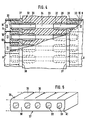
- the cover 1 consists of hollow profiles as shown in section in FIGS. 2 and 10.
- FIG. 2 consists of a cover plate 8, a base plate 9 and webs 10 connecting these, whereby cavities 11 are formed which (FIG. 2) have a rectangular cross section.
- the webs 10 and thus the cavities 11 extend in an expansion direction, preferably the longitudinal direction, of the swimming pool 3 such that the connection 4 is assigned to the cavities 11 at one end.
- the cover 1 is composed of a plurality of hollow profiles 12, 13, 14, 15 of different lengths arranged one behind the other, the length of the hollow profiles adjacent to the connection 4 being shorter than that of the others.
- length is to be understood as the dimension which extends in the direction of expansion mentioned.
- the hollow profile 12 has an air distribution profile 16, while at the other end of the cover 1, i.e. that the connection 4 opposite end of the hollow profile 15, a water distribution profile 17 is provided.
- the individual hollow profiles 12 to 15 are connected by means of articulated connections 18, 19 and 20 on the one hand articulated on the other hand to the outside in a water and airtight manner.
- the articulated connection 18, 19, 20 is such that a connection between the opposing cavities 11 of adjacent hollow profiles 12, 13, 14, 15 is always maintained.
- the lowering and the raising of the cover 1 in the swimming pool 3 is first explained in more detail.
- the air is supplied and removed to the connection 4 inside the swimming pool 3 via a spiral hose 21, a recess 23 being provided in the bottom 22 of the swimming pool 3 in the extension of the spiral hose 21.
- 3a shows the cover 1 in the floating state on the water 2.
- some air can be regularly supplied to the cover 1 by means of the pump 5 during this state, in order to maintain a certain overpressure of 1 to 2 mbar in the cavities 11 on the one hand and to prevent the penetration by a flooding, on the other hand and safely remove any remaining water.
- the latter is particularly advantageous if the cover 1 is to remain in the floating state for longer periods, for example in winter.
- the supply of small amounts of air is also particularly useful if - as shown - in the water distribution profile 17 on the bottom, i.e. Opposite the water surface, openings 24 are provided.
- the pump 5 is first switched to suction operation, so that water 24 into the one closest to it via the opening 24
- Hollow profile 15 is sucked in continuously. As a result, as shown in FIG. 3b, this hollow profile 15 slopes downwards.
- the articulated connection 20 is designed so that a maximum pivot angle a of about 30 ° can be achieved.
- the water drawn in through the opening 24 is also sucked into the next hollow profile 14 via the articulated connection 20, which can reach the same maximum swivel angle a to the next hollow profile 13.
- the pump 5 can now be put out of operation.
- the pump 5 can also be put out of operation automatically when water enters a corresponding monitoring device (not shown) between the opening 4 and the pump 5.
- the procedure for lifting the cover 1 is the reverse, i.e. air is supplied to the cover 1 by means of the pump 5 via the connection opening 4, the cavities 11 of the individual hollow profiles 12, 13, 14, 15 filling one after the other with air and beginning to float until the water is completely removed from the cover 1 via the opening 24 has been reached, in which case the state shown in FIG. 3a is reached.
- an inclination is once reached during lifting, in which the water can be drained more favorably by the pressure of the supplied air.
- a self-flooding cover 1 can also be achieved in that the pump 5 is completely separated for lowering and air can pass freely from the connection opening 4 into the open. To initiate the sinking process, however, ballast must then be provided at the end of the cover corresponding to the water distribution profile 17.
- the openings 24 can also be formed by valves which can be closed completely or partially, in such a way that the pump 5 pumps only slightly further after reaching the floating state shown in FIG. 3a, until an overpressure is reached and then stopped.
- the valves must be opened to flood.
- an opening 26 is created in the cover at the height thereof, the side walls of which are sealed against the interior of the cavities. In the floating state, this opening 26 can be closed by a closure (not shown).
- a material for the cover 1 are hygienically perfect and against chemicals contained in the bath water, for. B. chlorine or fluorine, resistant plastics such as rigid PVC and acrylic glass.
- the cover 1 can thereby also be made transparent. Color effects can also be achieved. If the cover is coated on the underside with an absorber film, such as the absorber film 25 in FIG. 2, the absorption of solar heat can be improved, particularly in the floating state.
- the risk of slipping when walking on the cover 1 can even be improved compared to walking on a conventional floor, apart from the fact that a more comfortable walking and standing feeling can be achieved.
- articulated connections 18, 19, 20 between the opposing cavities 11 of adjacent hollow profiles 12, 13 or 13, 14 or 14, 15 represent a particular problem, since on the one hand an articulated connection that is fluid-tight to the outside is to be achieved, and a simple one Manufacture and finally easy assembly should be possible.
- first connecting part 27 which can be inserted into the cavities 11 of the hollow profile 12
- second connecting part 28 which can be inserted into the cavities 11 of the adjacent hollow profile 13 and which has essentially the same configuration as the connecting part 27, a hinge part 29 between them opposite sides 30 and 31 of the two connecting parts 27 and 28 and grommets 32, which are inserted in the pairwise continuing openings 33 in the respective connecting part and the continuous transverse openings 34 of the hinge part 29.
- connecting part 27 or 28 does not necessarily have to extend over all cavities 11 of a hollow profile 12 or 13.
- such a connecting part 27 has a common section 35 starting from the side 30 as well as separate attachments 36 attached to it, which correspond to the grid of the cavities 11 of the hollow profile 12, each opening 33 including the common section 35 and one of the attachments 36, this approximately in the middle.
- the outer dimensions in the cross-sectional direction of the lugs 36 essentially correspond to the inner dimensions in the cross-sectional directions of the associated cavity 11 and are slightly larger. It is only necessary that the lugs 36 of the connecting part 27 can be inserted into the cavities 11 in a simple manner.
- the connecting part 27 consists of a soft-elastic, in particular rubber-elastic material such as a plastic, preferably with a Shore hardness of approximately 70 to 75.
- the material is impermeable to the fluids used in the application, here water and air, and is also resistant to the fluids resistant, ie is not attacked in particular by substances dissolved in the bath water, such as chlorine or fluorine. It is also preferably resistant to aging, particularly with regard to solar radiation and environmental influences.
- the material used for the connecting part 27 swells somewhat when exposed to the bath water, which enables the lugs 36 of the connecting part 27 to better fit and thus adhere to the walls of the respective cavities 11.
- the articulated part 29 can extend over several adjacent cavities 11 of the associated hollow profiles 12, 13 and therefore have a corresponding number of transverse openings 34, which of course in the same Grid dimensions are formed like that of the cavities 11 of the hollow profiles 12 and 13.
- the joint part 29 can also extend over only part of the cavities 11 of the cover 1.
- FIG. 7 shows a spout 32 which is suitable for connecting the connecting part 27, 28 to the joint part 29.
- Fig. 7b which shows the spout 32 in side view, also shows that it consists essentially of two sections 37 and 38.
- the section 37 can be inserted into the openings 33 of the connecting part 27 or 28, and the section 38 can be inserted into the transverse openings 34 of the joint part 29.
- the grommet 32 has an inner bore 39, which enables a fluid connection between the cavity 11 and the transverse opening 34 via the opening 33, and thus via the next grommet 32 with the cavity 11 of the adjacent hollow profile, as is readily apparent from FIG. 4 .
- each of the sections 37, 38 has a spreading device which, in the exemplary embodiment shown, is formed by barbs 40 and 41, which are formed in a sawtooth-like manner and surround the respective section 37, 38, the steep flanks 42 and 43 of the barbs 40 and 41, respectively 41 of sections 37 and 38 face each other. It is thereby achieved that the spout 32 can be inserted very easily into the opening 33 or the transverse opening 34, but can only be pulled out with extreme difficulty, also because the outer cross section (without barbs) of the sections 37 and 38 is somewhat larger than that Inner cross section of the associated opening 33 of the connecting part 27 or the transverse opening 34 of the joint part 29. Characterized ( y gl. Fig.
- the outer diameter of at least the barbs 41 of the corresponding section 38 is preferably significantly larger compared to the transverse bore 34 than the outer diameter of the barbs 40 of the other section 37 compared to the opening 33 of the connecting part 27, 28
- the invention is explained in more detail using an example in which the cavities 11 have a right cross section (cf. FIG. 2). If the opening 33 in the extension 36 and the cross-section of the section 37 of the spout 32 have an essentially circular cross-section, the spreading pressure exerted by the spout 32 or its section 37 may not be sufficient under certain circumstances (see FIG. 8a) Extend spreading effect into the corners 44 of the hollow profile 11, it may even happen that the extension 36 is pulled out of the corners 44. The tightness can therefore not always be guaranteed.
- the two hollow profiles 12 and 13 can now be pivoted relative to one another with the aid of the articulated connection 18. While the grommets 32 are hardly tilted in their position in alignment with the cavity 11, the joint part can be bent due to the inherent elasticity, specifically about an axis running parallel to the juxtaposition of the cavities 11. Due to the inherent elasticity of the connecting parts 27, 28 and the joint part 29, the tight seal to the outside is also ensured and the fluid connection via the openings 33, 39 and 34 remains guaranteed.
- the inherent elasticity is particularly supported by the integral design of the connecting part 27, 28 and the joint part 29 for a plurality of cavities 11 arranged next to one another in such a way that the flow connection between the adjacent cavities 11, in particular via the transverse opening 34, is not impaired, although a soft-elastic material is used.
- the swivel angle between adjacent hollow profiles 12, 13 or other adjacent hollow profiles 13, 14 or 14, 15 can also be determined by the length 1 taking into account the elasticity of the joint part 29. With the same material, the pivoting angle between adjacent hollow profiles 12, 13 or 13, 14 or 14.15 becomes smaller with a shorter length.
- a major advantage of the fluid-tight, articulated connection according to the invention is that assembly is extremely simple and can take place at the construction site, which is particularly advantageous in the case of large-area hollow profiles.
- the lugs 36 of the connecting part 27 (or the connecting part 28) are first inserted into the cavities 11.
- the spouts 32 are then inserted over their section 37 into the associated opening 33 of the connecting parts 27, which is simple since the flat flanks of the barbs are effective here.
- the same procedure is followed for the cavities 11 of the other hollow profile.
- the connecting part 29 is pushed over its transverse openings 34 over the sections 38 of the respective grommets 32, specifically for both hollow profiles 12, 13, which is also easily possible since the flat flanks of the barbs 41 are also effective here.
- the spreading effect is achieved by the barbs, so that a firm connection between the connecting parts 27, 28 and the hollow profiles 12, 13 on the one hand, the spouts 32 and the connecting parts 27, 28 on the other hand, and also between the spouts 32 and the joint part 29 is reached safely.
- This connection is also fluid-tight.
- the connecting parts 27, 28 and the joint part 29 are made of a material that swells somewhat when they come into contact with one of the fluids, here bathing water, the spreading effect is increased even further when in use.
- the parts of the articulated connection could be separated from one another by tensile forces acting in the direction of the openings and thus the hollow profiles could also be separated from one another.
- the loads can occur on the one hand only when walking over it, and on the other hand only occur when the cover is raised or lowered. There are no other tractive forces.
- an articulated connection designed according to the invention is not only able to achieve a secure fluid-tight articulated connection which can be achieved in a simple manner, it also shows that the. articulated connection on site, i.e. can be produced at the construction site, can be separated again in a simple manner and, moreover, is also inexpensive, especially since commercially available spouts can be used for the spouts under certain circumstances.
- the grommets consist of a commercially available, comparatively hard material, in particular also a plastic.
- the articulated connection is not only applicable to hollow profiles according to FIG. 2.
- the articulated connection can also be used for hollow profiles of other cross-sectional shapes.
- a hollow profile 51 as it is is shown in Fig. 10, which is formed by juxtaposed and firmly connected pipes, such that the cavities 52 have a circular cross-section.
- the cross-sectional shape of section 37 of spout 32 will then have a corresponding circular cross-section.
- other cross-sectional shapes are also possible, with the respective application playing an important role in the selection, for example whether or not the hollow profiles should be accessible when the swimming pool cover is in contact with the floor.
- the articulated connection according to the invention can also be used for a hollow profile arrangement, as is shown by way of example in FIG. 11.
- a cover should namely be applicable for every pool size, but this is opposed by manufacturing limits in the case of particularly wide swimming pools, since hollow profiles cannot generally be produced in any width. Therefore, according to a particular embodiment, the hollow profiles 12 to 15 can be formed by juxtaposing prefabricated hollow profile parts 53, 54.
- the hollow profile parts 53, 54 arranged next to one another can be connected to one another in a substantially rigid manner, but releasably, by means of angled projections 55, 56 provided on the respective edge.
- locking projections 57 and 58 which engage in one another elastically, on the angle projections 55 and 56.
- These angle projections 55, 56 can also be hollow (not shown).
- hollow profiles 12 to 15 of any width can be produced very quickly, and repair measures can also be carried out extremely quickly.
- all parts can be delivered prefabricated to the construction site and assembled there in a simple manner.
- the connecting parts 27, 28 and the joint parts 29 are each assigned to one of the hollow profile parts 53 and 54 in their width extent, i.e. have a corresponding number of openings 33 or transverse openings 34.
- an overlapping connection is also possible, in which case the distance between the adjacent cavities 11 of adjacent hollow profile parts, i.e. the dimensions of the connection 55 to 58 of the hollow profile parts must be taken into account.
- the lowering speed and the re-emerging speed of the cover 1 are determined not only by the performance of the pump 5 but also by the extent to which the water between the side edge 45 of the cover 1 and the side edge 46 of the pool 3 can flow down or up. Furthermore, depending on the size of the cover 1, more or less strong shrinking and stretching movements of the material of the cover 1 (both the hollow profiles 12, 13, 14, 15 and the articulated connections 18, 19, 20) must also be taken into account. Thus, a distance 47 must be provided on both sides of the cover 1 between the side edge 45 of the cover 1 and the side edge 46 of the swimming pool 3.
- a similar distance 48 which is caused solely by the shrinking and stretching movements of the material, must be provided between the end faces 49 of the cover 1 and 50 of the swimming pool 3. While the size differences caused by the spacings 47 and 48 are comparatively uncritical when the cover 1 rests on the floor 22, they can impair the covering effect when the cover 1 floats. Experiments have shown that with a pool width of approximately 4 m, the distance 47 must be approximately 8 to 10 cm. On the other hand, the distance 47 is advantageous, since cleaning devices such as floor vacuums are used even when the cover is floating and can be conveniently guided along the edge of the pool and, moreover, fixed installations can also be taken into account.
- connection parts 27, 28 are pulled apart at the edge to such an extent that, in the manner of a zipper, even with relatively little effort a slow separation of the entire connection from the edge is possible. For example, this can occur when walking on a very wide, lowered swimming pool cover lying on the floor.
- edge-side grommets 32 into the associated parts are glued in, which can take place at the construction site, and / or if in such a case the connecting parts 27, 28 and the hinge part 29 are glued to one another at their (outer) edges, which can also take place at the construction site.
- These edges 61 and 62 are indicated in FIGS. 5 and 6, respectively. If the grommets 32 are to be glued in, they must be glued into the openings 33 and 34 adjacent to these edges 61 and 62, respectively.
Landscapes
- Engineering & Computer Science (AREA)
- Architecture (AREA)
- Civil Engineering (AREA)
- Structural Engineering (AREA)
- Toys (AREA)
- Professional, Industrial, Or Sporting Protective Garments (AREA)
- Joints Allowing Movement (AREA)
- Body Structure For Vehicles (AREA)
- Blow-Moulding Or Thermoforming Of Plastics Or The Like (AREA)
- Bridges Or Land Bridges (AREA)
Claims (14)
Priority Applications (1)
| Application Number | Priority Date | Filing Date | Title |
|---|---|---|---|
| AT84107757T ATE37924T1 (de) | 1983-07-06 | 1984-07-04 | Fluiddichte gelenkige verbindung zwischen hohlprofilen. |
Applications Claiming Priority (2)
| Application Number | Priority Date | Filing Date | Title |
|---|---|---|---|
| DE3324406A DE3324406C1 (de) | 1983-07-06 | 1983-07-06 | Fluiddichte gelenkige Verbindung zwischen Hohlprofilen |
| DE3324406 | 1983-07-06 |
Publications (3)
| Publication Number | Publication Date |
|---|---|
| EP0131249A2 EP0131249A2 (fr) | 1985-01-16 |
| EP0131249A3 EP0131249A3 (en) | 1985-05-15 |
| EP0131249B1 true EP0131249B1 (fr) | 1988-10-12 |
Family
ID=6203321
Family Applications (1)
| Application Number | Title | Priority Date | Filing Date |
|---|---|---|---|
| EP84107757A Expired EP0131249B1 (fr) | 1983-07-06 | 1984-07-04 | Liaison à charnière étanche pour profilés creux |
Country Status (5)
| Country | Link |
|---|---|
| US (1) | US4626005A (fr) |
| EP (1) | EP0131249B1 (fr) |
| AT (1) | ATE37924T1 (fr) |
| CA (1) | CA1241249A (fr) |
| DE (1) | DE3324406C1 (fr) |
Families Citing this family (32)
| Publication number | Priority date | Publication date | Assignee | Title |
|---|---|---|---|---|
| US5853203A (en) * | 1996-03-13 | 1998-12-29 | Epic Technical Group, Inc. | Barbed tubular connectors |
| DE19641751B4 (de) * | 1996-10-10 | 2009-07-09 | Evonik Degussa Gmbh | Zweikomponenten-Anbindungselement |
| US5954372A (en) * | 1997-05-13 | 1999-09-21 | Agricultural Products, Inc. | Apparatus for splicing drip tape |
| US6024086A (en) * | 1998-07-22 | 2000-02-15 | Rich; Albert Clark | Solar energy collector having oval absorption tubes |
| FR2785930B1 (fr) * | 1998-11-13 | 2001-03-23 | Beatrice Houlle | Panneau souple submersible pour bassin constitue d'elements modulaires creux allonges et ulilisation correspondante |
| FR2802183B1 (fr) * | 1999-12-10 | 2002-02-22 | Biodome | Procede de fabrication d'un dispositif de connexion entre un recipient et un contenant, dispositif de connexion correspondant et ensemble pret a l'emploi comprenant un tel dispositif |
| US7311882B1 (en) * | 2003-01-24 | 2007-12-25 | Sandia National Laboratories | Capillary interconnect device |
| FR2866381B1 (fr) * | 2004-02-18 | 2006-05-19 | Raymond Nexon | Profile destine a la construction d'un plancher pour bassin et susceptible de flotter ou d'etre immerge |
| DE202004018927U1 (de) * | 2004-12-07 | 2005-02-24 | Ifco Systems Gmbh | Transportkasten mit klappbaren Seitenteilen aus Kunststoff |
| US7406980B2 (en) | 2005-08-29 | 2008-08-05 | Masco Corporation Of Indiana | Waterway connection |
| US20090025921A1 (en) * | 2005-09-27 | 2009-01-29 | Uponor Innovation Ab | Capillary Tube System |
| US7845029B2 (en) * | 2005-12-08 | 2010-12-07 | Ami Kolechstein | Floatable swimming pool cover |
| US7415991B2 (en) | 2005-12-20 | 2008-08-26 | Masco Corporation Of Indiana | Faucet spout with water isolating couplings |
| US7766043B2 (en) | 2006-05-26 | 2010-08-03 | Masco Corporation Of Indiana | Faucet including a molded waterway assembly |
| US8991425B2 (en) | 2006-05-26 | 2015-03-31 | Delta Faucet Company | Waterway assembly including an overmolded support plate |
| US7717133B2 (en) | 2007-01-31 | 2010-05-18 | Masco Corporation Of Indiana | Spout tip attachment |
| US7748409B2 (en) | 2007-01-31 | 2010-07-06 | Masco Corporation Of Indiana | Overmold interface for fluid carrying system |
| US7806141B2 (en) | 2007-01-31 | 2010-10-05 | Masco Corporation Of Indiana | Mixing valve including a molded waterway assembly |
| US7721761B2 (en) * | 2007-01-31 | 2010-05-25 | Masco Corporation Of Indiana | Diverter integrated into a side sprayer |
| EP2155988B1 (fr) | 2007-05-09 | 2013-10-30 | Ami Kolechstein | Couverture de piscine flottante |
| WO2009126887A1 (fr) | 2008-04-10 | 2009-10-15 | Masco Corporation Of Indiana | Gouttière moulée pour un robinet à double poignée |
| CA2859105C (fr) * | 2008-05-21 | 2018-11-27 | Masco Corporation Of Indiana | Asperseur et inverseur integres a cote d'un robinet de cuisine |
| CA2727077C (fr) | 2008-06-25 | 2013-10-01 | Masco Corporation Of Indiana | Robinet central a bec montable |
| US8104512B2 (en) | 2008-09-25 | 2012-01-31 | Masco Corporation Of Indiana | Spout tip retention method |
| US8739826B2 (en) | 2011-03-11 | 2014-06-03 | Masco Corporation Of Indiana | Centerset faucet body and method of making same |
| BE1020373A3 (nl) * | 2012-01-16 | 2013-08-06 | Moortgat Bv Met Beperkte Aansprakelijkheid | Zwembadvloerinrichting, zwembad, en werkwijzen om een beweegbare zwembadvloer in hoogte te verstellen en een zwembad te reinigen. |
| US8931500B2 (en) | 2012-02-17 | 2015-01-13 | Masco Corporation Of Indiana | Two handle centerset faucet |
| FR2988415B1 (fr) * | 2012-03-21 | 2014-10-31 | Bluewood | Fond mobile pour piscine |
| NL2010725C2 (en) * | 2013-04-26 | 2014-10-29 | Dejatech Ges B V | Modular heat exchanger with sections interconnected by connectors. |
| FR3016384B1 (fr) * | 2014-01-16 | 2016-11-25 | Aqua Invest | Panneau souple submersible pour bassin et procede de fabrication |
| US10792639B2 (en) * | 2017-04-26 | 2020-10-06 | Massachusetts Institute Of Technology | Reconfigurable chemical synthesis systems and methods |
| DE102020201428A1 (de) * | 2020-02-06 | 2021-08-12 | Alfmeier Präzision SE | Verbindungselement und Versorgungsleiste für eine Ventilanordnung |
Family Cites Families (17)
| Publication number | Priority date | Publication date | Assignee | Title |
|---|---|---|---|---|
| GB117891A (en) * | 1918-02-25 | 1918-08-08 | Thomas John Carr | Improvements relating to Hose Couplings. |
| US2798745A (en) * | 1954-02-23 | 1957-07-09 | Lewen R Nelson | Multiple-tube hose coupling |
| GB1156031A (en) * | 1965-12-23 | 1969-06-25 | Reginald George Bowler | Improvements in or relating to Fluid Flow Connectors. |
| US3469863A (en) * | 1967-04-05 | 1969-09-30 | Trico Products Corp | Fluid coupling assembly |
| US3590855A (en) * | 1969-04-01 | 1971-07-06 | Multiplex Co | Remote-supply liquid dispensing system |
| US3767233A (en) * | 1971-08-10 | 1973-10-23 | None Such Enterprises Inc | Coupling device for flexible tubing and the like |
| US3873134A (en) * | 1973-01-04 | 1975-03-25 | Michael Sammaritano | Apparatus for joining preformed conduits |
| DE2361725A1 (de) * | 1973-12-12 | 1975-06-19 | Fritz Bruecher | Schutzabdeckung, insbesondere fuer schwimmbecken |
| DE2713793A1 (de) * | 1977-03-29 | 1978-10-05 | Manfred Janouch | Absenkbare abdeckung fuer fluessigkeitsbehaelter, insbesondere fuer schwimmbecken |
| US4160465A (en) * | 1977-04-19 | 1979-07-10 | Hsu Charles J | Emergency water leak plug |
| DE2724287A1 (de) * | 1977-05-28 | 1978-12-07 | Wolfgang Ing Grad Schroetter | Schwimmbadabdeckung |
| US4156540A (en) * | 1977-08-30 | 1979-05-29 | Parker-Hannifin Corporation | Sealant for hose fittings |
| US4229843A (en) * | 1978-07-18 | 1980-10-28 | Bombardier Limited | Pool floor |
| FR2452653A1 (fr) * | 1979-03-26 | 1980-10-24 | Carrion Gerard | Raccord souple et extensible pour tubes d'alimentation de fluide |
| US4236258A (en) * | 1979-04-17 | 1980-12-02 | French Masterpieces, Incorporated | Automatic swimming pool cover |
| DE2943366C2 (de) * | 1979-10-26 | 1983-10-06 | Gustav 8922 Peiting Stifter | Absenkbare und begehbare Abdeckung für Flüssigkeitsbehälter, insbesondere für Schwimmbecken |
| DE3215883C2 (de) * | 1982-04-29 | 1984-04-26 | Festo-Maschinenfabrik Gottlieb Stoll, 7300 Esslingen | Adapterblock zur Anwendung in der Fluid-Technik |
-
1983
- 1983-07-06 DE DE3324406A patent/DE3324406C1/de not_active Expired
-
1984
- 1984-07-03 US US06/627,421 patent/US4626005A/en not_active Expired - Fee Related
- 1984-07-04 EP EP84107757A patent/EP0131249B1/fr not_active Expired
- 1984-07-04 AT AT84107757T patent/ATE37924T1/de not_active IP Right Cessation
- 1984-07-06 CA CA000458359A patent/CA1241249A/fr not_active Expired
Also Published As
| Publication number | Publication date |
|---|---|
| EP0131249A3 (en) | 1985-05-15 |
| DE3324406C1 (de) | 1984-11-22 |
| CA1241249A (fr) | 1988-08-30 |
| EP0131249A2 (fr) | 1985-01-16 |
| ATE37924T1 (de) | 1988-10-15 |
| US4626005A (en) | 1986-12-02 |
Similar Documents
| Publication | Publication Date | Title |
|---|---|---|
| EP0131249B1 (fr) | Liaison à charnière étanche pour profilés creux | |
| EP0220389B1 (fr) | Panneau pour couvrir les murs ou les plafonds | |
| DE3050690C2 (de) | Wärmetauscher mit einer Wärmetauschermatte aus elastomerem Material | |
| DE69208824T2 (de) | Modulares Kanalelement für Entwässerungsrinnen | |
| EP0125382B1 (fr) | Tuyaux de drainage comprenant un manchon | |
| DE2358325A1 (de) | Vorrichtung fuer rohrverbindungen | |
| DE2246379A1 (de) | Schutzrohrabschnitt fuer erdkabel o.dgl | |
| EP1038485A2 (fr) | Agencement de joint de la périphérie d'une cuve sanitaire avec un mur ou le sol d'une pièce | |
| EP0532459B1 (fr) | Manchon de jonction pour deux tuyaux en matière plastique. | |
| EP0933488A2 (fr) | Grille de plafond pour salles blanches | |
| DE2362445C3 (de) | Dichtungsanordnung an gegeneinander abzudichtenden hohlprofilteilen | |
| DE2446475A1 (de) | Spielzeug-steckbaustein | |
| DE2700414A1 (de) | Dichtungsprofil fuer spundwandschloesser | |
| DE2943366C2 (de) | Absenkbare und begehbare Abdeckung für Flüssigkeitsbehälter, insbesondere für Schwimmbecken | |
| EP0096413B1 (fr) | Elément de couverture de toit notamment pour capter de l'énergie solaire | |
| DE3310692C2 (de) | Einsatz für ein Kabelkanalrohr | |
| DE2213183C2 (de) | Abdeckung für Mauern od.dgl | |
| DE2819359A1 (de) | Rohrverbindungsteil | |
| DE19857881B4 (de) | Schutzvorrichtung gegen Hochwasser und/oder Rückhaltesicherung für umweltschädigende flüssige Medien | |
| DE3146275C2 (de) | Bodenablauf | |
| DE69326827T2 (de) | Fugenvorrichtung | |
| DE2903573C2 (de) | Bauelement, insbesondere Baustein | |
| DE3526535A1 (de) | Profil zum abdichten von nasszellen o. dgl. | |
| DE3926867C2 (fr) | ||
| AT399549B (de) | Biegsames rohr mit einer rohrwand aus einem gewindeartigen gewickelten bandstreifen |
Legal Events
| Date | Code | Title | Description |
|---|---|---|---|
| PUAI | Public reference made under article 153(3) epc to a published international application that has entered the european phase |
Free format text: ORIGINAL CODE: 0009012 |
|
| AK | Designated contracting states |
Designated state(s): AT BE CH FR GB IT LI LU NL SE |
|
| PUAL | Search report despatched |
Free format text: ORIGINAL CODE: 0009013 |
|
| AK | Designated contracting states |
Designated state(s): AT BE CH FR GB IT LI LU NL SE |
|
| 17P | Request for examination filed |
Effective date: 19851115 |
|
| 17Q | First examination report despatched |
Effective date: 19860819 |
|
| D17Q | First examination report despatched (deleted) | ||
| GRAA | (expected) grant |
Free format text: ORIGINAL CODE: 0009210 |
|
| AK | Designated contracting states |
Kind code of ref document: B1 Designated state(s): AT BE CH FR GB IT LI LU NL SE |
|
| PG25 | Lapsed in a contracting state [announced via postgrant information from national office to epo] |
Ref country code: SE Effective date: 19881012 Ref country code: NL Effective date: 19881012 Ref country code: IT Free format text: LAPSE BECAUSE OF FAILURE TO SUBMIT A TRANSLATION OF THE DESCRIPTION OR TO PAY THE FEE WITHIN THE PRESCRIBED TIME-LIMIT;WARNING: LAPSES OF ITALIAN PATENTS WITH EFFECTIVE DATE BEFORE 2007 MAY HAVE OCCURRED AT ANY TIME BEFORE 2007. THE CORRECT EFFECTIVE DATE MAY BE DIFFERENT FROM THE ONE RECORDED. Effective date: 19881012 |
|
| REF | Corresponds to: |
Ref document number: 37924 Country of ref document: AT Date of ref document: 19881015 Kind code of ref document: T |
|
| GBT | Gb: translation of ep patent filed (gb section 77(6)(a)/1977) | ||
| ET | Fr: translation filed | ||
| NLV1 | Nl: lapsed or annulled due to failure to fulfill the requirements of art. 29p and 29m of the patents act | ||
| PG25 | Lapsed in a contracting state [announced via postgrant information from national office to epo] |
Ref country code: GB Effective date: 19890704 Ref country code: AT Effective date: 19890704 |
|
| PG25 | Lapsed in a contracting state [announced via postgrant information from national office to epo] |
Ref country code: LU Free format text: LAPSE BECAUSE OF NON-PAYMENT OF DUE FEES Effective date: 19890731 Ref country code: LI Effective date: 19890731 Ref country code: CH Effective date: 19890731 Ref country code: BE Effective date: 19890731 |
|
| PLBE | No opposition filed within time limit |
Free format text: ORIGINAL CODE: 0009261 |
|
| STAA | Information on the status of an ep patent application or granted ep patent |
Free format text: STATUS: NO OPPOSITION FILED WITHIN TIME LIMIT |
|
| 26N | No opposition filed | ||
| BERE | Be: lapsed |
Owner name: STIFTER GUSTAV Effective date: 19890731 |
|
| GBPC | Gb: european patent ceased through non-payment of renewal fee | ||
| REG | Reference to a national code |
Ref country code: CH Ref legal event code: PL |
|
| PGFP | Annual fee paid to national office [announced via postgrant information from national office to epo] |
Ref country code: FR Payment date: 19930625 Year of fee payment: 10 |
|
| PG25 | Lapsed in a contracting state [announced via postgrant information from national office to epo] |
Ref country code: FR Effective date: 19950331 |
|
| REG | Reference to a national code |
Ref country code: FR Ref legal event code: ST |