EP0131289A1 - Ringartiges Daten-Sende- und Empfangnetzwerk - Google Patents
Ringartiges Daten-Sende- und Empfangnetzwerk Download PDFInfo
- Publication number
- EP0131289A1 EP0131289A1 EP84107946A EP84107946A EP0131289A1 EP 0131289 A1 EP0131289 A1 EP 0131289A1 EP 84107946 A EP84107946 A EP 84107946A EP 84107946 A EP84107946 A EP 84107946A EP 0131289 A1 EP0131289 A1 EP 0131289A1
- Authority
- EP
- European Patent Office
- Prior art keywords
- station
- data
- break
- stations
- transmission
- Prior art date
- Legal status (The legal status is an assumption and is not a legal conclusion. Google has not performed a legal analysis and makes no representation as to the accuracy of the status listed.)
- Withdrawn
Links
- 230000005540 biological transmission Effects 0.000 title claims abstract description 155
- 230000015556 catabolic process Effects 0.000 claims abstract description 151
- 238000012545 processing Methods 0.000 claims abstract description 27
- 238000001514 detection method Methods 0.000 claims abstract description 9
- 238000000034 method Methods 0.000 claims description 15
- 241000711981 Sais Species 0.000 claims 1
- 230000003213 activating effect Effects 0.000 claims 1
- 230000006854 communication Effects 0.000 description 56
- 238000004891 communication Methods 0.000 description 56
- 230000007175 bidirectional communication Effects 0.000 description 7
- 101000835996 Caenorhabditis elegans Slit homolog 1 protein Proteins 0.000 description 5
- 238000012546 transfer Methods 0.000 description 5
- 238000010586 diagram Methods 0.000 description 4
- 230000002457 bidirectional effect Effects 0.000 description 3
- 239000003550 marker Substances 0.000 description 3
- 230000015654 memory Effects 0.000 description 3
- 230000008569 process Effects 0.000 description 3
- 230000004048 modification Effects 0.000 description 2
- 238000012986 modification Methods 0.000 description 2
- 230000004044 response Effects 0.000 description 2
- 101000985261 Homo sapiens Hornerin Proteins 0.000 description 1
- 102100028627 Hornerin Human genes 0.000 description 1
- 230000002159 abnormal effect Effects 0.000 description 1
- 230000008859 change Effects 0.000 description 1
- 238000010276 construction Methods 0.000 description 1
- 230000000694 effects Effects 0.000 description 1
- 230000006870 function Effects 0.000 description 1
- 230000003252 repetitive effect Effects 0.000 description 1
- 238000000926 separation method Methods 0.000 description 1
- 238000011144 upstream manufacturing Methods 0.000 description 1
Images





Classifications
-
- H—ELECTRICITY
- H04—ELECTRIC COMMUNICATION TECHNIQUE
- H04L—TRANSMISSION OF DIGITAL INFORMATION, e.g. TELEGRAPHIC COMMUNICATION
- H04L12/00—Data switching networks
- H04L12/28—Data switching networks characterised by path configuration, e.g. LAN [Local Area Networks] or WAN [Wide Area Networks]
- H04L12/42—Loop networks
- H04L12/437—Ring fault isolation or reconfiguration
Definitions
- the present invention relates to a loop-type. data transmission/reception network which can assure trouble-free transmission and reception of information from and to each data communication station if any part of the data transmission/reception route (i.e., common data bus) is disconnected.
- a conventional loop-type network of data transmission/reception is exemplified by Japanese Patent Application Publication No. 57-129048, the disclosure of which is hereby incorporated by reference.
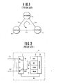
- the disclosed system comprises, e.g., as shown in Fig. 1, three stations A, B, and C interconnected via a'single data transmission/reception route (common data bus) to form a loop, the processed data in each station being transferred to the adjacent station only in one direction as shown by the arrow in Fig. 1, i.e., the counterclockwise direction as viewed in Fig. 1.
- a'single data transmission/reception route common data bus
- the station A detects the break-down of the data transmission/reception route L 3 due to the absence of received data from the station C for a predetermined period of time and informs the remaining stations B and C that leg L 3 of data transmission/reception route has broken down. Thereafter information can still be sent to each station by performing bidirectional transmission between each station via the remaining legs of the data transmission/reception route at a predetermined timing in a sequence which can be illustrated as A ⁇ B ⁇ C ⁇ B ⁇ A Q B ....
- the loop-back processing is carried out if one leg of the data transmission/reception route breaks down.
- each station (station B is shown as an example in Fig. 2) is provided with a switch circuit 1 which controls the direction of transmission/reception of data.
- a switch circuit 1 which controls the direction of transmission/reception of data.
- an input bus In is connected to a leg of the data transmission/reception route L 1 leading from the station A at the previous stage of the network and an output bus OUT is connected to another leg of the transmission/reception route L 2 leading to the station C at the next stage.
- the switch positions of the switch circuit 1 are changed at predetermined intervals to reverse the directions of data transmission and reception.
- numeral 2 denotes a Central Processing Unit for controlling the overall data processing performed at each station
- numeral 3 denotes an interface called SCI (Serial Communication Interface) for inputting and outputting the transmission/reception signals serving to convert the bits of information from parallel (byte-wide) form to serial (bit-wide) form and from serial to parallel form
- SCI Serial Communication Interface
- ROM Read-Only Memory
- RAM Random-Access Memory
- interface 6 denotes an input/output port used by the microcomputer.
- One example of a microcomputer of such configuration is HD-6801 manufactured by Hitachi Co., Ltd.
- the configuration of information packets to be transmitted in the above-described network system i.e., the data of a single frame comprises, as shown in Fig. 3, a marker slot SYN for identifying the frame, two channel slots SLT 1 and SLT 2 and subsequent break-down information slot SLT 3 for reporting the break-down state of the data transmission/reception network.
- the slot SLT 3 comprises an eight-bit code conveying the above-described break-down information.
- the station A detects the break- down in the data transmission/reception leg L3 after it fails to receive any data for a period exceeding a predetermined time. Thereafter, the station A transmits a byte to the station B in the next stage in which a most significant bit (MSB) D 7 is set to a "1" and the remaining bits are set to "0" as represented by (10000000) in binary form and by "80 H " in hexadecimal-coded decimal form (H denotes a hexadecimal-coded decimal notation).
- MSB most significant bit
- the station B determines from the above-described byte received from the station A in which the most significant bit is "1" that there is a break-down in the data transmission/reception route and furthermore sends the same information on the break-down to the station C. Together with the transmission of the break- down information to the station C, the direction of the transmission/reception direction is switched at predetermined intervals after the passage of a predetermined time T B .
- the station C also recognizes that a break-down has occurred from the break-down-representative data received from the station B and thereafter switches its direction of communication repeatedly at predetermined intervals after the passage of a predetermined time T C .
- a loop-type data transmission/reception network system having a plurality of stations and a data transmission/reception route, each station including (a) means for detecting breakdowns in the data transmission/reception route between the station itself and adjoining station in a second direction opposite to a first direction in which the data is normally transmitted; (b) means responsive to the detection of a break-down in the data transmission/ reception route between the station itself and adjoining station by the detecting means for transmitting the break-down information to either one of the adjoining stations according to the transmission direction; and (c) means for transmitting the information on a reversal of the transmission direction of data in the station itself via the data transmission/reception route to the adjoining station together with the break-down information transmitted by the break-down information transmitting means.
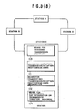
- Fig. 5 (A) shows a general construction of a first preferred embodiment according to the present invention.
- the loop-type network system according to the present invention comprises a plurality of stations (A, B, C, and D) and a single common bus (data transmission/ reception route) for interconnecting the stations in a loop so that information can be transmitted in a single direction around the loop when the common bus normally interconnects the stations.
- Each station comprises: (a) a line-break-down detection means 101 for detecting the break-down in the leg of the data transmission/reception route between the station itself and station at the previous stage from which the data is to be received; (b) a break-down information transmission means 102 for transmitting break-down information to the next station in the direction of transmission so as to report the occurrence of the break-down of the data transmission/reception route; and (c) a transmission-direction reversing means 103 for reversing the data transmission/reception direction at the station itself when a predetermined condition is satisfied.
- each station is provided with a timing information transmission means 104 for transmitting timing information representing the number of stations from the break-down location to the current station.
- a loop-type network system of a first preferred embodiment comprises a plurality of stations A, B, and C and a single data transmission/reception bus (a common bus) interconnecting these stations in a loop in the same way as shown in Fig. 1.
- each station is constructed as shown in Fig. 2 in terms of hardware.
- Figs. 6(A) and 6(B) are operational flowcharts of a single normal- and back-up-operation program to be executed by the CPU (Central Processing Unit) 2 in each station shown in Fig. 2.
- CPU Central Processing Unit
- one frame of data comprises a marker slot SYN identifying the frame and three data slots SLT 1 through 3.
- SLT 1 and SLT 2 are channel slots which contain data about control signals for terminal equipment to be connected to each station (for example, head lamp, mirror, and turn signal lamp, etc.)
- the SLT 3 contains eight bits of break-down information.
- the information representing the absence of break-down in the bus is represented as [00] H in binary-coded hexadecimal (also represented as [0000 0000] in binary notation).
- Each station in the data transmission/ reception route carries out the sequence of steps SP(I) ⁇ SP(2) ⁇ SP(3) ⁇ SP(4) ⁇ SP(5) ⁇ SP(15) ⁇ SP(16) ⁇ SP(17) or steps SP(1) ⁇ SP(10) ⁇ SP(11) ⁇ SP(12) ⁇ SP(15) ⁇ SP(16) ⁇ SP(17) within a known interval of time, thus transmitting information in a single direction (counterclockwise direction as in the conventional system shown in Fig. 1).
- step SP(1) the CPU 2 determines whether a signal has been received by the SCI 3 from bit state of the SCI 3.
- the CPU 2 reads the received signal from the SCI 3 into the CPU 2 itself.
- the software timer T M 1 is cleared, which timer is used to detect break- downs in data transmission/reception to be described later.
- the CPU 2 determines whether a flag FLG 1 is zero, the flag FLG 1 indicating whether or not bidirectional loop-back-type communication is being performed. In this case, the FLG 1 is zero since the data transmission/reception route is normal and the result at step (4) is NO so that the CPU 2 goes to the step SP(5).
- the CPU 2 reads the data of the break-down information slot SLT 3 from the received data and determines whether the most significant bit (MSB) of the received SLT 3R has been set to a "1".
- MSB most significant bit
- the CPU 2 recognizes that the data transmission/reception route is operating normally when-the MSB is at a "0". In the case when the MSB is at a "1", the CPU 2 recognizes that some point of the data transmission/reception route has broken down.
- step SP(15) the data of each of the slots to be transmitted is set according to known processes outside the scope of this invention.
- the data for each slot is transmitted whenever the processing shown in Figs. 6(A) and 6(B) is carried out.
- step SP(16) the data frame set up in the preceding step (15) is outputted via the SCI 3 onto the corresponding data transmission/reception path.
- step SP(17) the CPU 2 again determines whether the above-described flag FLG 1 has been set to "1". Since in this case the flag FLG 1 has remains at "0", the result is "NO" and one cycle of execution in Figs. 6(A) and 6( B ) has been completed.
- the CPU 2 of the station A determines whether the flag FLG 1, indicating whether or not bidirectional communication in the loop-back method is being executed, is zero. In the station A, since the flag FLG 1 is still zero, the result is "NO" and the routine goes to the steps SP (11) and SP(12).
- step SP(10) the CPU 2 carries out the same processing as the step SP(4).
- the step SP(11) serves to increment the software timer TM 1 for detecting the break-down.
- the CPU determines whether the contents of the above-described timer TM 1 exceed a preset time T 0 -In the step SP(12), the data will not be transmitted from the station C to the station A even after the time indicated by the timer TM 1 exceeds the preset time T 0 since there is a break-down in the leg L 3 of the data transmission/reception route. Therefore, the CPU 2 of the station A recognizes that a break-down in the leg L 3 of the data transmission/reception route has occurred when the time indicated by the software timer TM 1 reaches the preset time T 0 . Thereafter, the routine goes to the step SP(13).
- the CPU 2 resets to "0" a distance data variable Pset representing how many stations distant from the point where the break-down occurred the subsequent station is. That is to say, as described above, since the break-down occurred in the leg L 3 of the data transmission/reception route between the stations C and A and the station A is located at the break-down location, a distance value of "0" is stored in the distance variable Pset of the station A. Therefore, the distance variable Pset in the subsequent station B. stores a distance value of "1" and that in the subsequent station C stores the value "2". The significance of these values will be described later.
- the CPU 2 writes the value "80 H " in binary-coded hexadecimal representation into the break-down information slot SLT 3 to be transmitted. That is to say, "1" is written into the MSB (Most Significant Bit D 7 ) of the break-down information slot SLT 3 comprising eight bits of data.
- the steps SP(8) et seq. are executed in which the above-described flag FLG 1 is set to "1" to indicate that the station A has entered the bidirectional communication mode with the adjacent station E.
- the CPU 2 sets flag FLG 2 to a "I", the flag FLG 2 indicating the control of the communication direction reversal process.
- the values of the distance data variable Pset, break-down information slot SLT 3 and the flags FLG 1 and FLG 2 are all set.
- the steps SP(15) and SP(16) cause the contents of the break-down information slot SLT 3 set in the step SP(14) ("80 H ") to be transmitted to the subsequent station B.
- step SP(17) From the next step SP(17), since the flag FLG 1 was set to "1" in the above-described step (8) so that the determination result is YES, control passes to step SP(18) is executed.
- step SP(18) the CPU 2 determines whether the output of the above-described break-down information slot SLT 3 has been completed. The result is "NO" during the output of the break-down information slot SLT 3. The next step SP(21) is carried out after completion of the output of the break-down information slot SLT 3.
- the CPU 2 determines.. whether a flag FLG 3, indicating whether the output of the break-down information slot SLT 3 is completed after reversal of the transmission direction, is set to "1" or not. Since in this case the flag FLG 3 remains at a "0" during the output of the break-down information slot SLT 3, the result is NO so that the CPU 2 executes the next step SP(22).
- the CPU 2 calculates the sum of the received break-down information slot SLT 3 R and the contents of the distance data variable Pset set in the above-described step (13) and determines whether the sum is "83 H ". At this time, since data from the station C is not received by the station A, the above-described SLT 3 R is indefinite and the result is "NO".
- the routine goes to the step SP(23) wherein the CPU 2 determines whether the flag FLG 2 set in the above-described step SP(9) is at a "1" or "0" (that is to say, whether it holds a value of "1” or not).
- the result is "YES”, and so control passes to the following step SP(24).
- step SP (24) the CPU 2 decrements the contents of the flag FLG 2 by 1 i.e., resets the flag FLG 2 to a "0" so that the contents of the flag FLG 2 in the station A is again turned to "0".
- the routine goes to the step SP(21) in which the switching signal is outputted via the interface 6 to the switch circuit 1 to reverse the data transmission/reception direction shown in Fig. 2 (in this case, the transmission direction in the station A is reversed from the counterclockwise direction to the clockwise direction).
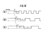
- the station A detects the break-down in the leg L 3 of the data transmission/reception route between the stations C and A at time T a1 ⁇ After transmitting the predetermined break-down information to the station B, the transmission direction is reversed from the counterclockwise direction (L) to the clockwise direction (R) as shown in A 1 of Fig. 8.
- step SP(5) the CPU 2 determines whether the most significant bit (MS B ) of the received break-down information slot SL T 3R is at a "1". The answer is YE S since the break- down information slot SLT 3R from the station A was changed to "80 H ". Therefore, the routine goes to the step SP(6).
- the C PU 2 of the station B adds 1 to the break-down information slot SLT 3 R ("80 H ") received from the station A to derive the value of the break-down information slot SLT 3 to be transmitted from the station B . Therefore, in this case, the value of the break-down information slot SLT 3 becomes "81 H ".
- the value of the distance variable Pset is derived by the station B . Specifically, after the addition of "1" to the value of the received break-down information slot SLT 3 R , a value wherein the most significant bit (MSB) is reset to "0" is assigned to the distance variable Pset. Since in this case the value of the received break-down information slot SLT 3 R is "80H", the addition of "1" to the received break-down information slot SLT 3 R yields "81 H " and the value of the distance variable Pset yields "01 H " (hereinafter represented by "1") after the most significant bit is reset to "0".
- MSB most significant bit
- the station B is programmed such that after the reception of the break-down information slot SLT 3, the value of which is "80 H " from the station A, the value of the break-down information slot SLT 3 to be retransmitted is changed to "81 H " and the distance variable Pset is set to "1" (01 H ).
- the data is then transmitted in the steps SP(15) and SP(16). Since the answer at the subsequent step SP(17) is YES, the step SP(18) ⁇ SP(19) ⁇ SP(22) will be executed next.
- step SP(22) Since, in the above-described step SP(22), the value of the distance variable Pset is "1" and the value of the received break-down information slot SLT 3 R is "80 H ", their sum is “81 H " and so the answer at the step SP(22) is NO. Thereafter, the sequence of steps SP(23) ⁇ SP(24) ⁇ SP(21) ⁇ ... is executed. After the flag FLG 2 is reset to the "0" in the step SP(24), the transmission direction in the station B is reversed from the counterclockwise direction (L) to the clockwise direction (R).
- Fig. 8 illustrates the above-described operation.
- the communication direction is changed from the counterclockwise direction (L) to the clockwise direction (R) at time B 1 shown in Fig. 8.
- the series of steps SP(1) ⁇ SP(10) ⁇ SP(15) ⁇ SP(16) ⁇ SP(17) ⁇ SP(18) ⁇ SP(19) ⁇ SP(22) ⁇ SP(23) ⁇ END ⁇ SP(1) ⁇ ... is repeatedly executed.
- the station A executes the routine shown in Figs. 6(A) and 6(B) by way of the following sequence: SP(1) ⁇ SP(2) ⁇ SP(3) ⁇ SP(4) ⁇ SP(15) ⁇ SP(16) ⁇ SP(17) ⁇ SP(18) ⁇ SP(19) ⁇ SP(22) ⁇ SP(23) ⁇ END ⁇ SP(1) ⁇ ... and does not again perform the reversal of the communication direction to the counterclockwise direction (L).
- step SP(22) since in the step SP(22) in this case, the value of the distance data variable Pset in the station A is "0" (00 H ) and the value of the break-down information slot SLT 3 R received from. the station B is "81 H " , sum is "81 H ", and the answere at step (22) is NO.
- the flag FLG 2 is already reset to "0". and answer at the step SP(25) is NO.
- the station C executes the following sequence in response to receipt of the break-down information slot SLT 3 from the station B: steps SP(1) ⁇ SP(2) ⁇ SP(3) ⁇ SP(4) ⁇ SP(5) ⁇ SP(6) ....
- the CPU 2 of the station C adds 1 to the value "81 H " of the received slot SLT 3 R from the station B to derive the value of the slot SLT 3 to be retransmitted from the station C.
- the value "82 H " is written into the break-down information slot SLT 3 in the station C.
- step SP(7) the same calculation as described in the case of the station B is executed for the distance data variable Pset in the station C.
- the value "2" (02 H ) is stored as the distance data variable Pset.
- the flag FLG 1 is set to "1" in the step SP(8) and the step SP(9) is executed.
- the flag FLG 2 is set to a "1"
- the series of steps SP(15) ⁇ SP(16) ⁇ SP(17) 7 SP(18) are executed and the steps of SP(19) ⁇ SP(22) are executed after the break-down information slot SLT 3 is outputted.
- the slot SLT 3 to be outputted at the step SP(16) is transmitted via the data transmission/reception route in which the break-down has occurred since the station C has not yet changed its transmission direction in the direction of (L).
- step SP(22) the value of the distance data variable Pset yields "2" (02 H ) and the value of the break-down information slot SLT 3 R received from the station B is "81 H ". Therefore, their sum satisfies the condition of step (22) so that the step SP(25) is executed next.
- the CPU 2 of the station C determines whether the station presently executing the step SP(25) is either of the stations sandwiching the break-down location (hereinafter referred to as an end station). In more detail, the CPU 2 of the station C determines whether or not the value of the above-described distance data variable Pset is either "0" or "2". Since the value of Pset in the station C is "2", the answer in this case is YES so that the step SP(26) is subsequently executed. Note that in the shown embodiment, the value "2" represents an end station because are three stations in the network. The value "2" may be replaced by "n-1", where "n" is the number of stations in the system.
- the CPU 2 sets the flag FLG 2 to "I". Since in this case the value of the flag FLG 2 had already been turned to "1" in the step SP(9). the value of the flag FLG 2 remains "1".
- step (28) the CPU 2 sets the flag FLG 3 to "1" to indicate that transmission of the slot SLT 3 has been completed.
- step SP (1) when the cycle starts again from the step SP (1), the series SP(1) ⁇ SP(10) ⁇ SP(15) ⁇ SP(16) ⁇ SP(17) ⁇ SP(18) ⁇ SP(19) is executed. Since in this case the flag FLG 3 has previously been set to "1" in the step SP(28), control will pass from step (19) to SP(20) to reset the flag FLG 3 to "0". Thereafter, control passes to the step SP(21).
- the function of the step SP(21) is to change the transmission direction, i.e., the communication direction of the station C is reversed from the counterclockwise direction (L) to the clockwise direction (R).
- the above-described processing is executed starting from time t cl at which the break-down information slot SLT 3 is received from the station B.
- the communication direction is changed to the clockwise direction (R) (C 1 in Fig. 8).
- the CPU 2 of the station C executes the sequence of steps SP(1) ⁇ SP(10) ⁇ SP(15) ⁇ SP(16) ⁇ SP(17) ⁇ SP(18) ⁇ SP(19) ... .
- the processing in the step SP(22) is thereafter executed since the value of the flag FLG 3 is "0" in this case,
- step 2 Since the flag FLG 2 is set to "1" in the above-described step SP(26), the condition of step (23) is satisfied and control passes to the step SP(24). In the step SP(24), the value of the flag FLG 2 is reset to a "0" so that the value of the flag FLG 2 becomes "0".
- step (22) Since the value of the distance variable Pset in the station B is "1" (01 H ) and the value of the break- down information slot SLT 3 R received from the station C is "82 H “, their sum is "83 H “, the condition of step (22) is satisfied. Thus, control passes to the step SP(25).
- step (25) Since the value of the distance data variable Pset in the station B is "1" the answer at step (25) is NO. Thereafter, the step SP(27) is executed.
- step SP(27) the value of the break-down information slot SLT 3 to be transmitted from the station B to the station A and the value of the distance data variable Pset are updated.
- the value of the distance data variable Pset is the value of the break-down information slot SLT 3 modified by resetting the most significant bit (MSB) to "0". Since in this case the slot SLT 3 is changed to "83 H ", the value of the distance variable Pset is changed to "3" (03 H ). After the execution of these steps, the flag FLG 3 is set to "1" in the step SP(28).
- the station B will not again perform the changing operation of the transmission direction until the next data frame is received.
- the break-down information slot SLT 3 is changed to "83 H " and therefore the contents of the distance variable Pset is changed to "3" (03 H ).
- the flag FLG 3 is set to "1" in the step SP(28).
- step SP(18) After the output of the slot SLT 3 is completed, control will pass from the step SP(18) to the step (19).
- the station B does not repeat the reversal of the transmission direction until the next data frame is received from the station A.
- the station C can receive data from the station B, the station C does not immediately carry out the reversal of the communication direction since the condition of step SP(22) is not satisfied and the flag FLG 2 is already reset to "0".
- the series of steps SP(1) ⁇ SP(2) ⁇ SP(3) ⁇ SP(4) SP(15) ⁇ SP(16) ⁇ SP(17) ⁇ SP(18) ⁇ SP(19) ⁇ SP(22) is executed. Since the value of the distance data variable Pset in the station A is "0" and the values of the break- down information slot SLT 3 R received from the station B is "83 H ", the condition of step (22) is satisfied and the step SP(25) is executed next.
- step (25) is satisfied since the value of the distance data variable Pset in the station A is "0" so that and step SP(26) will be executed next. Therefore, the value "1" is assigned to the flag FLG 2 and thereafter the flag FLG 3 is set to "1" in the step SP(28).
- the CPU 2 of the station A executes the series of steps SP(1) ⁇ SP(10) ⁇ SP(15) ⁇ SP(16) ⁇ SP(17) ⁇ SP(18) ⁇ SP(19). Since the flag FLG 3 is currently set to "1" in the step SP(28) of the previous cycle, the flag FLG3 is reset to "0" in the step SP(22) and thereafter the transmission direction in the station A is changed from the counterclockwise direction (L) to the clockwise direction (R) in the step SP(21).
- step SP(22) Since the value of the distance variable Pset is changed to "3" in the station B and the value of the break-down information slot SLT 3 received from the station A is "80H", the answer at the step SP(22) is YES and control passes to step SP(25).
- step (25) Since the value of the distance data variable Pset in the station B is "3" in this case, the condition of step (25) is not satisfied. Thus, the routine goes to the step SP(27) wherein the values of the slot SLT 3 and Pset are modified.
- the value "81 H” is selected to be transmitted by the station B as the value of slot SLT 3 since the contents of the break-down information slot SLT 3R received from the station A is "80 H " and is incremented by 1.
- step SP(19) is executed. Since the flag FLG 3 has been set to "1", the routine goes to the step SP(20) wherein the flag FLG 3 is reset to "0". The transmission direction is reversed in the step. SP(21). Consequently, the transmission direction of the station B is changed from the counterclockwise direction (L) to the clockwise direction (R).
- the communication is carried out with the most significant bit (MSB) of the break-down information slot SLT 3 turned to the "1" after the occurrence of the break-down in the data transmission/reception route.
- MSB most significant bit
- the conditions are selected so as to reverse the communication direction when the sum of the values of the received break-down information slot SLT 3 R and the distance variable Pset in each station equals "83 H ".
- the reversal operation is reciprocated so that the necessary information can be transmitted to all stations.
- the transmission speed will not remarkably be reduced.
- the loop-back type data transmission/reception system of this embodiment prevents the communications between the adjacent stations from being disrupted by errors in the reversal periods of the communication directions for each station.
- Figs. 9(A) and 9(B) illustrate a program executed by each station of a second embodiment according to the present invention.
- the second preferred embodiment comprises a plurality of stations A, B, and C and a single data transmission/ reception route in the form of a loop as shown in Fig. 1 and the structure of each station is the same as shown in Fig. 2.
- the program illustrated by the flowcharts of Figs. 9 (A) and 9(B) is executed by the CPU 2 shown in Fig. 2.
- One frame of data to be transmitted between each station comprises, as shown in Fig. 3, a marker slot SYN for identifying the frame and three data slots SLT 1 through SLT 3 as in the conventional data format.
- the two slots SLT 1 and SLT 2 are channel slots including control signal data for a terminal equipment (for example, head lamp, mirror, and turn signal lamp, etc.) to be connected to each station.
- the remaining slot SLT 3 includes a break-down byte comprising eight bits.
- the break-down byte is "00 H " in binary-coded hexadecimal representation when there is no break- down in the data transmission/reception route (also represented as "0000 0000” in binary notation).
- each station transmits data only in one direction around the loop via the steps ST(1) ⁇ ST(2) ⁇ ST(3) ⁇ ST(4) ⁇ ST(19) ⁇ ST(20) ⁇ END ⁇ ST(1) ⁇ ... (the counterclockwise direction as shown in Fig. 1 in the same way as the conventional system).
- Fig. 9(A) the CPU 2 of each station in the step ST(l) determines whether a signal has been received- by the SCI 3 from the state of the SCI 3 (Serial Communication Interface 3).
- the CPU 2 of each station thereafter reads the value of the inputted signal in the SCI 3 into the CPU 2 itself in step ST(2).
- the CPU 2 of each station clears a software timer TM 1 used to detect the break-down in the data transmission/reception route in step ST(3).
- the CPU 2 of each station reads the break-down information of the slot SLT 3 from among the data received and determines whether the most significant bit (MSB) in the break-down information slot SLT 3 is "1" or "0". If the MSB thereof is "0.”, the CPU 2 recognizes that the data transmission/reception route is normal (has not broken down) and, on the other hand, the CPU 2 recognizes that the data transmission/reception route is abnormal (has a malfunctioning component) if the most significant bit (MSB) is "1". These steps are the same as those in the first preferred embodiment.
- step ST(19) the data for the slots to be transmitted is set according to the conventional processing system. Whenever the program of Figs. 9 (A) and 9(B) is executed, the data for each slot is transmitted. In the step ST(20), the data for each slot set in the above-described step ST(19) is outputted via the data transmission/reception route by the SCI 3.
- the CPU 2 of the station A checks the state of the flag FLG 1, which indicates whether the bidirectional communication in the loop-back method is being performed or not as in the first preferred embodiment. Since the flag FLG 1 is still at "0" at this stage in the station A, the answer is NO and the routine goes to the subsequent step ST(14).
- step ST(14) the software timer TM 1 for detecting break-down is started and in the subsequent step ST(15), the CPU 2 of the station A determines whether the contents of the above-described timer TM 1 exceeds a preselected time T 0 .
- the CPU 2 of the station A recognizes that a break-down has occurred in the data transmission/reception route L 3 between the stations C and A and executes the subsequent step ST(16).
- the value "1" is written into the least significant bit (LSB) of the slot SLT 3 for the above-described break-down information, resulting in a byte value represented as "01 H " in binary-coded hexadecimal. (H denotes hexadecimal notation used to represent one byte of information).
- a preselected time T 2 is set in another software timer TM 2 which measures a period of communication direction reversal.
- the value "O1 H " is stored in a variable M BRK representing the distance from the break-down location (the number of stations from the break-down location) in the step ST(18).
- the flag FLG 1 is set to "1" to indicate that bidirectional communication is being executed by the loop-back method.
- the slot SLT 3 (the value thereof being "01 H ") set in the step ST(16) is transmitted to the- subsequent station B in the steps ST(19) and ST(20).
- the CPU 2 executes the step ST(6) wherein the value of the timer TM 2 is decremented. Thereafter, the routine goes to the step ST(7) wherein the CPU 2 determines whether the timer value TM 2 is 0 i.e., whether the time indicated by the timer TM 2 has reached the preselected time T 2 . If the result is NO, the CPU 2 maintains the transmission enable sta.te. If the result is YES, the preselected time T 2 is again set in the timer TM 2 in step ST(8) and, then, the communication direction is reversed in the step ST(9).
- the CPU 2 of the station B executes the sequence of steps ST(1) ⁇ ST(2) ⁇ 5T(3) ⁇ ST(4) ⁇ ST(5). Since the execution result in the step ST(5) is NO in the first cycle of execution after break-down, the step ST(10) is executed next.
- the value "02 H " is stored in the distance data register M BRK . This corresponds to the number of stations between the break-down location and the station B itself inclusive and the value of the received slot SLT 3R is incremented by "1".
- the resulting value (“02 H " in the station B) corresponds to the order of the station from the break-down location in the original direction of transmission.
- the value "02 H " of the distance data register M BRK is assigned to the break- down information slot SLT 3 to be transmitted to the subsequent station C.
- the value "03 H " is stored in the distance data register M BRK indicating that the station C is the third station from the break-down location.
- the preselected time 3T 2 is set in the software timer TM 2 to determine the communication direction reversal period of the station C.
- the station C executes the reversal of the communication direction repeatedly whenever the period of 3T2 has elasped after the slot SLT 3. represented in "02 H " is received from the station B.
- the reversal period of the communication direction is set to a value different from that of the adjacent station according to the accumulated number of stations from the break-down location. Even if the accuracy of the timer in each station is inadequate, the communication direction can be ensured to be the same as that of the adjacent station so that the transfer of data can be achieved.
- the period of reversal of the communication direction in each station is progressively increased in proportion to the number of stations from the break-down location.
- the same effect can be obtained by carrying out the processing shown in Fig. 11 in place of step ST(12).
- the CPU 2 in the step ST(22) determines whether the contents of the distance data register M BRK stored in the step ST(10) is an even number. If it is an even number, the period of reversal of the communication direction is Set to the period 2T 2 in the step ST(24) On the other hand, if the contents of the register M BRK is an odd number, the period of reversal of the communication direction is set to T 2 in the step ST(23).
- the stations A and C at the odd-numbered locations from the break-down location carry out the reversal of the communication direction at periods of T 2 after the CPU 2 of these stations recognize the break-down.
- the station B which is at an even- numbered location from the break-down location, the reversal of the communication direction is executed at periods of 2 T 2 .
- the period of reversal the communication direction is 2T 2 at most so that there is no significant delay in the communication over the system.
- the data transmission/ reception system can transmit information between adjacent stations securely even in cases where bidirectional communication by the loop-back method must be performed after the occurrence of a break-down without significantly reducing the transmission rate.
- the data transmission/reception system can prevent communications between adjacent stations from being disrupted by errors in the period of reversal of the communication direction among stations.
Landscapes
- Engineering & Computer Science (AREA)
- Computer Networks & Wireless Communication (AREA)
- Signal Processing (AREA)
- Small-Scale Networks (AREA)
Applications Claiming Priority (4)
| Application Number | Priority Date | Filing Date | Title |
|---|---|---|---|
| JP124350/83 | 1983-07-08 | ||
| JP58124350A JPS6016743A (ja) | 1983-07-08 | 1983-07-08 | ル−プ型ネツトワ−クシステム |
| JP125830/83 | 1983-07-11 | ||
| JP58125830A JPS6018041A (ja) | 1983-07-11 | 1983-07-11 | ル−プ型ネツトワ−クシステム |
Publications (1)
| Publication Number | Publication Date |
|---|---|
| EP0131289A1 true EP0131289A1 (de) | 1985-01-16 |
Family
ID=26461037
Family Applications (1)
| Application Number | Title | Priority Date | Filing Date |
|---|---|---|---|
| EP84107946A Withdrawn EP0131289A1 (de) | 1983-07-08 | 1984-07-06 | Ringartiges Daten-Sende- und Empfangnetzwerk |
Country Status (2)
| Country | Link |
|---|---|
| US (1) | US4593154A (de) |
| EP (1) | EP0131289A1 (de) |
Cited By (2)
| Publication number | Priority date | Publication date | Assignee | Title |
|---|---|---|---|---|
| EP0163921A1 (de) * | 1984-05-07 | 1985-12-11 | Siemens Aktiengesellschaft | Messdatenverarbeitungsanlage |
| EP0605795A3 (de) * | 1992-12-07 | 1995-08-09 | Alcatel Nv | Verfahren zur Handhabung von Kopffeldern in Ringnetzwerken. |
Families Citing this family (24)
| Publication number | Priority date | Publication date | Assignee | Title |
|---|---|---|---|---|
| CA1244110A (en) * | 1984-12-27 | 1988-11-01 | Masashi Hirome | Transmitting data processing system |
| US4723120A (en) * | 1986-01-14 | 1988-02-02 | International Business Machines Corporation | Method and apparatus for constructing and operating multipoint communication networks utilizing point-to point hardware and interfaces |
| JPS62239641A (ja) * | 1986-04-11 | 1987-10-20 | Hitachi Ltd | 同報通信方式 |
| US4933933A (en) * | 1986-12-19 | 1990-06-12 | The California Institute Of Technology | Torus routing chip |
| JPH0752886B2 (ja) * | 1987-12-19 | 1995-06-05 | 富士通株式会社 | ループ型ネットワークの構成方法 |
| US5016243A (en) * | 1989-11-06 | 1991-05-14 | At&T Bell Laboratories | Automatic fault recovery in a packet network |
| US4999829A (en) * | 1989-11-06 | 1991-03-12 | At&T Bell Laboratories | Automatic fault recovery in a packet network |
| US4993015A (en) * | 1989-11-06 | 1991-02-12 | At&T Bell Laboratories | Automatic fault recovery in a packet network |
| EP0726665A2 (de) * | 1989-12-26 | 1996-08-14 | Kabushiki Kaisha Komatsu Seisakusho | Serielle Steuereinheit |
| US5471623A (en) * | 1991-02-26 | 1995-11-28 | Napolitano, Jr.; Leonard M. | Lambda network having 2m-1 nodes in each of m stages with each node coupled to four other nodes for bidirectional routing of data packets between nodes |
| JPH04271542A (ja) * | 1991-02-27 | 1992-09-28 | Nec Corp | データ伝送回路 |
| JP2752265B2 (ja) * | 1991-05-10 | 1998-05-18 | 株式会社東芝 | Lanからの切離し機能を持つ計算機システム |
| CA2072171A1 (en) * | 1991-06-24 | 1992-12-25 | Kaori Kishi | Clock recovery system capable of automatically switching a direction of a clock pulse sequence from one to another |
| US5442620A (en) * | 1992-03-26 | 1995-08-15 | At&T Corp. | Apparatus and method for preventing communications circuit misconnections in a bidirectional line-switched ring transmission system |
| CA2096504C (en) * | 1993-05-18 | 1996-02-06 | Emanuel Weissmann | Self-healing drop and insert communication network |
| JP2821979B2 (ja) * | 1993-09-13 | 1998-11-05 | 富士通株式会社 | リング構成ネットワークの制御方式 |
| JP3226393B2 (ja) * | 1993-09-20 | 2001-11-05 | 富士通株式会社 | パス・プロテクション・スイッチ・リング・システム |
| US5669065A (en) * | 1994-09-15 | 1997-09-16 | Mine Radio Systems Inc. | Completely redundant communication system utilizing radiating transmission line |
| JPH10290251A (ja) * | 1997-04-15 | 1998-10-27 | Yazaki Corp | ネットワークにおける異常復旧装置 |
| US6721508B1 (en) | 1998-12-14 | 2004-04-13 | Tellabs Operations Inc. | Optical line terminal arrangement, apparatus and methods |
| US6965572B1 (en) * | 2000-06-07 | 2005-11-15 | At&T Corp. | Loopback capability for bi-directional multi-protocol label switching traffic engineered trucks |
| DE10047923C2 (de) * | 2000-09-27 | 2003-04-10 | Siemens Ag | Verfahren zur Erzeugung einer Verbindungs-Redundanz für ein serielles Kommunikationssystem mit einer Mastereinheit und einer Mehrzahl von Slaveeinheiten, die untereinander als Aneinanderreihung von Punkt-zu-Punkt-Verbindungen in Linientopologie verbunden sind, sowie korrespondierendes serielles Kommunikationssystem |
| CH701066B1 (de) | 2007-11-21 | 2010-11-30 | Metaphysics Sa | Kommunikationsbaustein, netzwerk mit einem solchen kommunikationsbaustein und verfahren zum betrieb. |
| EP2434687A4 (de) * | 2009-07-29 | 2012-03-28 | Huawei Tech Co Ltd | Datenübertragungsverfahren, kommunikationseinrichtung und kommunikationssystem |
Citations (2)
| Publication number | Priority date | Publication date | Assignee | Title |
|---|---|---|---|---|
| DE2644616A1 (de) * | 1976-10-02 | 1978-04-06 | Fraunhofer Ges Forschung | Kommunikationssystem zum austausch von nachrichten |
| GB2064919A (en) * | 1979-12-04 | 1981-06-17 | Standard Telephones Cables Ltd | Data transmission loops optical repeaters |
Family Cites Families (3)
| Publication number | Priority date | Publication date | Assignee | Title |
|---|---|---|---|---|
| CH584492A5 (de) * | 1974-12-10 | 1977-01-31 | Hasler Ag | |
| JPS57129048A (en) * | 1981-02-04 | 1982-08-10 | Hitachi Ltd | Loop data transmitting device |
| JPS57208746A (en) * | 1981-06-18 | 1982-12-21 | Toyota Motor Corp | Transmission controlling system |
-
1984
- 1984-06-28 US US06/625,432 patent/US4593154A/en not_active Expired - Lifetime
- 1984-07-06 EP EP84107946A patent/EP0131289A1/de not_active Withdrawn
Patent Citations (2)
| Publication number | Priority date | Publication date | Assignee | Title |
|---|---|---|---|---|
| DE2644616A1 (de) * | 1976-10-02 | 1978-04-06 | Fraunhofer Ges Forschung | Kommunikationssystem zum austausch von nachrichten |
| GB2064919A (en) * | 1979-12-04 | 1981-06-17 | Standard Telephones Cables Ltd | Data transmission loops optical repeaters |
Non-Patent Citations (2)
| Title |
|---|
| IBM TECHNICAL DISCLOSURE BULLETIN, vol. 14, no. 12, May 1972, pages 3617-3618, New York, USA; L.M. AUDRETSCH Jr. et al.: "Turn-around fault bypass in single-rail loop communication network" * |
| IBM TECHNICAL DISCLOSURE BULLETIN, vol. 19, no. 10, March 1977, pages 3824-3828, New York, USA; G.J. LAURER et al.: "Automatic loop reconfigurator" * |
Cited By (2)
| Publication number | Priority date | Publication date | Assignee | Title |
|---|---|---|---|---|
| EP0163921A1 (de) * | 1984-05-07 | 1985-12-11 | Siemens Aktiengesellschaft | Messdatenverarbeitungsanlage |
| EP0605795A3 (de) * | 1992-12-07 | 1995-08-09 | Alcatel Nv | Verfahren zur Handhabung von Kopffeldern in Ringnetzwerken. |
Also Published As
| Publication number | Publication date |
|---|---|
| US4593154A (en) | 1986-06-03 |
Similar Documents
| Publication | Publication Date | Title |
|---|---|---|
| US4593154A (en) | Loop-type data transmission/reception network | |
| US5168497A (en) | Packet communication processing method | |
| EP0147644B1 (de) | Token-Ring mit sekundären Sendegelegenheiten | |
| EP0378401A2 (de) | Datenübertragungssystem | |
| US5165091A (en) | Firmware download from a remote terminal to an optical network terminal in a digital loop carrier system | |
| US3845472A (en) | Data communication system employing a series loop | |
| US5495480A (en) | Packet transmission system having timer for circuit disconnection | |
| US4498082A (en) | Method and apparatus for locating a discontinuity in a data transmission ring | |
| WO1984002628A1 (en) | Method and apparatus for graceful preemption on a digital communications link | |
| EP0074672A2 (de) | Asynchrones Datenbus-System | |
| EP0371593B1 (de) | Verfahren zur Initialisierung oder Synchronisierung einer Übertragungsleitung | |
| US5550827A (en) | Control of the interchange of data packets in a network | |
| EP0374883B1 (de) | System für Querverkehr zwischen lokalen Netzen | |
| US4967409A (en) | Network system of programmable controllers | |
| US6654385B1 (en) | Message division communication method and communication system | |
| US6510449B1 (en) | Data transmission system | |
| JPH0311701B2 (de) | ||
| EP0216379A2 (de) | Übertragungsverfahren und Einrichtung dafür | |
| JPH0351143B2 (de) | ||
| KR0157389B1 (ko) | 교환기내 디지탈 가입자 장치의 통신제어회로 | |
| US3963867A (en) | Method for indicating a free-line state in a binary data communication system | |
| JP2522910B2 (ja) | ラインバツフア切替方式 | |
| KR100261028B1 (ko) | 티씨유와 단말기 사이의 프로토콜 구조 및 그 처리방법 | |
| JP2844402B2 (ja) | セルトラヒック監視装置 | |
| JPS6390929A (ja) | 多重伝送装置 |
Legal Events
| Date | Code | Title | Description |
|---|---|---|---|
| PUAI | Public reference made under article 153(3) epc to a published international application that has entered the european phase |
Free format text: ORIGINAL CODE: 0009012 |
|
| 17P | Request for examination filed |
Effective date: 19840706 |
|
| AK | Designated contracting states |
Designated state(s): DE FR GB |
|
| RAP1 | Party data changed (applicant data changed or rights of an application transferred) |
Owner name: NISSAN MOTOR CO., LTD. |
|
| STAA | Information on the status of an ep patent application or granted ep patent |
Free format text: STATUS: THE APPLICATION IS DEEMED TO BE WITHDRAWN |
|
| 18D | Application deemed to be withdrawn |
Effective date: 19860703 |
|
| RIN1 | Information on inventor provided before grant (corrected) |
Inventor name: SUZUKI, TADASHI Inventor name: FUTAMI, TOORU Inventor name: TAKEDA, HITOSHI Inventor name: KISHI, NORIMASA Inventor name: TOMIKASHI, MINORU |