EP0131346A2 - Dispositif de chargement pour magnétophone à cassette - Google Patents
Dispositif de chargement pour magnétophone à cassette Download PDFInfo
- Publication number
- EP0131346A2 EP0131346A2 EP84201023A EP84201023A EP0131346A2 EP 0131346 A2 EP0131346 A2 EP 0131346A2 EP 84201023 A EP84201023 A EP 84201023A EP 84201023 A EP84201023 A EP 84201023A EP 0131346 A2 EP0131346 A2 EP 0131346A2
- Authority
- EP
- European Patent Office
- Prior art keywords
- cassette
- cassette holder
- loading device
- ratchet
- shaft
- Prior art date
- Legal status (The legal status is an assumption and is not a legal conclusion. Google has not performed a legal analysis and makes no representation as to the accuracy of the status listed.)
- Withdrawn
Links
Images


Classifications
-
- G—PHYSICS
- G11—INFORMATION STORAGE
- G11B—INFORMATION STORAGE BASED ON RELATIVE MOVEMENT BETWEEN RECORD CARRIER AND TRANSDUCER
- G11B15/00—Driving, starting or stopping record carriers of filamentary or web form; Driving both such record carriers and heads; Guiding such record carriers or containers therefor; Control thereof; Control of operating function
- G11B15/675—Guiding containers, e.g. loading, ejecting cassettes
- G11B15/67544—Guiding containers, e.g. loading, ejecting cassettes with movement of the cassette parallel to its main side and subsequent movement perpendicular thereto, i.e. front loading
- G11B15/67555—Guiding containers, e.g. loading, ejecting cassettes with movement of the cassette parallel to its main side and subsequent movement perpendicular thereto, i.e. front loading the second movement only being made by the cassette holder
Definitions
- the invention relates to a loading device on a magnetic tape cassette device with a lifting device and with a frame-shaped cassette holder which can be raised and lowered by the lifting device and which has an ejection slide which can be locked in an inserted position by means of a ratchet lever.
- the cassette inserted into the device is centered using centering pins.
- For taking the motor-driven cassette lifting device lifts the received in the cassette receiving cartridge from the Hästellun q g in the Ausirestellun.
- the cassette must be locked in the cassette holder when it is lowered into the working position.
- a loading device for a magnetic tape cassette device in which the locking takes place by means of a so-called shadow pawl, which has a heart curve and a pin traversing the heart curve.
- the pin At the Pushing a cassette into the cassette holder by hand engages the pin in the hollow of the heart curve, so that the inserted cassette is locked in the inserted position.
- the pin moves out of the hollow of the heart curve and a spring moves an ejection slide with the cassette into the ejection position. It is disadvantageous here that the cassette must always be triggered again to eject it.
- a latching lever of the ejection slide in the insertion position which can be pivoted away from its locking position by means of a rocker arm mounted on it, which functionally moves past a release element when the cassette holder is lowered and can be pivoted in this way when the cassette holder is lifted is that he pivots the latch lever out of the locking position.
- the locking is therefore released very simply by utilizing the movement forces which are in the lifting movement for triggering. This is easy and economical.
- the rocker arm and the release member determine in which direction of movement of the lifting device the latch lever is moved out of its locking position and in which direction it is not.
- the double-armed rocker arm is designed in the manner of a hanging rocker.
- the rocker arm has two free arms, of which the first free arm interacts with a release lug of a resilient release arm arranged on the player housing, while the second free arm bumps against the latch lever when unlocked.
- the ejection slide is locked only on one side and ejection slides arranged on both sides of the cassette holder work parallel to one another.
- the ejection slides arranged on both sides of the cassette holder are provided with toothed racks which mesh with gear wheels which are connected to one another via a shaft. The ejection slides on both sides of the cassette holder work this way strictly coupled in parallel.
- the rotational movement of the shaft can be braked by means of a braking device during lifting movements.
- a brake sleeve is arranged on the shaft, which is provided with a ratchet device, which locks the brake sleeve against rotational movements when the cassette holder rises, and that a braking medium between the locked brake sleeve and the shaft brakes the shaft rotation.
- the ratchet device consists of a ratchet gear and a ratchet spring leaf acting on the ratchet gear.
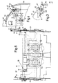
- a loading device with a cassette holder 3, into which a cassette 5 is inserted.
- the exemplary embodiment is a video cassette with a swiveling closure cover 7 and a cassette slide 9 which can be pushed back on the cassette housing.
- centering pins 13 are inserted into the cassette head 11.
- the video tape 15 is pulled in the working position by means of a threading and unthreading mechanism, not shown, around a head drum, not shown, with a rotatable head disc.
- the threading and unthreading mechanisms are not described in detail since they are irrelevant in the context considered here.
- the cassette holder 3 can be moved with the aid of a lifting device from the playing position according to FIG. 1 into an ejecting and retracting position according to FIG. 2.
- This lifting device consists of a control motor 17 which drives a control disk, not shown.
- a contour of this control disk, not shown, is traversed by a feeler lever, also not shown, by means of a feeler pin.
- An actuating rod which is articulated between the feeler pin and the pivot point of the feeler lever engages with its other end on a lift lever, namely between its pivot bearing and a free end.
- the free end of this lift lever engages with a lift pin 19 on two lifting levers 21a and 21b which can be pivoted about pivot points 23, 24.
- the joint system comprising the two mutually coupled lifting levers 21a and 21b engages in grooves 26 of lifting rods 27 with a lifting pin 25.
- the control motor 17 can thus raise the cassette holder 3 via the control disk (not shown) and the lifting levers 21a and 21b and the lifting rods 27.
- the centering pins 13 are pulled out of the cassette, as can be seen in FIG. 2 and which enables the cassette 5 to be ejected.
- Sliders 29 are arranged on both sides of the frame-shaped cassette holder 3 and can be moved back and forth in the ejection direction. From Fig. 6 it can be seen that the two slides 29 are provided with serrations 31 which mesh with gear wheels 33. The slides 29 engage in the interior of the cassette holder 3 by means of driver pins 35 and can reach behind the cassette slide 9, as can be seen from FIG. 2.
- the gear wheels 33 are connected to one another via a shaft 37 (FIG. 6).
- q sbremse 39 On the shaft 37 a Reibun is arranged q sbremse 39, which consists of a brake sleeve 40 and arranged on the brake sleeve 40 ratchet gear 41st A ratchet spring leaf 43 interacts with the ratchet gear 41 (FIG. 2) and allows the brake sleeve 40 to rotate in one direction only.
- a braking viscous grease for example silicone grease
- a locking device 45 shown in more detail in FIGS. 2, 3 and 4, is provided on the cassette holder 3.
- This locking device consists of a pawl lever 49 which can be pivoted about an axis 47 and which is provided with a notch 51.
- the pawl lever 49 is made of plastic and is equipped with a molded-on spring arm 53, which can press behind a nose 55 of the cassette holder 3.
- a double-armed rocker arm 59 can be pivoted about a further axis 57 located next to axis 47.
- This Rocker arm in the manner of a hanging rocker can, when it hits a release lug 63 of a release arm 65 with a first free arm 61, pivot the latch lever 49 so far that a second free arm 67 presses the latch lever 49 upward.
- the cassette holder 3 When the cassette has been played and is to be ejected, the cassette holder 3 is raised by actuating the control motor 17. When lifting, the first free arm 61 abuts the release lug 63, and the second free arm 67 tilts the pawl lever 49 upward. The bolt 69 which has now become free allows the spring 71 to eject the cassette 5 by means of the spring 71. This ejection movement is braked in that the ratchet spring leaf 43 now abuts a tooth of the ratchet gear 41. The brake sleeve 40 is thus blocked and the shaft 37 is braked by means of the grease between the brake sleeve 40 and the shaft 37. The ejection process is very slow.
Landscapes
- Feeding And Guiding Record Carriers (AREA)
- Packaging Of Annular Or Rod-Shaped Articles, Wearing Apparel, Cassettes, Or The Like (AREA)
Applications Claiming Priority (2)
| Application Number | Priority Date | Filing Date | Title |
|---|---|---|---|
| DE3325053 | 1983-07-12 | ||
| DE3325053A DE3325053C2 (de) | 1983-07-12 | 1983-07-12 | Vorrichtung an einem Kassettenspieler mit einer Hebevorrichtung |
Publications (2)
| Publication Number | Publication Date |
|---|---|
| EP0131346A2 true EP0131346A2 (fr) | 1985-01-16 |
| EP0131346A3 EP0131346A3 (fr) | 1986-03-05 |
Family
ID=6203741
Family Applications (1)
| Application Number | Title | Priority Date | Filing Date |
|---|---|---|---|
| EP84201023A Withdrawn EP0131346A3 (fr) | 1983-07-12 | 1984-07-11 | Dispositif de chargement pour magnétophone à cassette |
Country Status (5)
| Country | Link |
|---|---|
| US (1) | US4639801A (fr) |
| EP (1) | EP0131346A3 (fr) |
| JP (1) | JPS6077053U (fr) |
| CA (1) | CA1225740A (fr) |
| DE (1) | DE3325053C2 (fr) |
Cited By (2)
| Publication number | Priority date | Publication date | Assignee | Title |
|---|---|---|---|---|
| EP0156443A3 (en) * | 1984-03-28 | 1986-10-08 | Philips Patentverwaltung Gmbh | Cover for a magnetic tape cassette apparatus |
| DE3707830A1 (de) * | 1986-03-11 | 1987-09-17 | Mitsubishi Electric Corp | Kassettenhalterkonstruktion |
Families Citing this family (3)
| Publication number | Priority date | Publication date | Assignee | Title |
|---|---|---|---|---|
| US4853805A (en) * | 1987-11-05 | 1989-08-01 | Ampex Corporation | Multi-cassette indexing mechanism for a tape transport |
| JPH0740395B2 (ja) * | 1989-04-11 | 1995-05-01 | 三菱電機株式会社 | カセットローディング装置 |
| US5513053A (en) * | 1993-10-22 | 1996-04-30 | Sony Corporation | Combination casing member, cam member and cassette holder for a cassette loading mechanism |
Family Cites Families (13)
| Publication number | Priority date | Publication date | Assignee | Title |
|---|---|---|---|---|
| AT259257B (de) * | 1965-08-25 | 1968-01-10 | Philips Nv | Aufzeichnungs und Wiedergabegerät |
| GB1266012A (fr) * | 1968-03-06 | 1972-03-08 | ||
| US3854784A (en) * | 1972-11-29 | 1974-12-17 | Ibm | Information media handling system |
| JPS5341394Y2 (fr) * | 1973-08-29 | 1978-10-05 | ||
| JPS5589941A (en) * | 1978-12-28 | 1980-07-08 | Victor Co Of Japan Ltd | Mounting and demounting unit for tape container |
| JPS6037725Y2 (ja) * | 1978-12-28 | 1985-11-11 | クラリオン株式会社 | テ−ププレヤ用オ−トロ−デイング装置 |
| JPS5656002U (fr) * | 1979-10-03 | 1981-05-15 | ||
| JPS5698738A (en) * | 1979-12-29 | 1981-08-08 | Pioneer Electronic Corp | Tape recorder |
| US4467378A (en) * | 1980-11-19 | 1984-08-21 | Staar S. A. | Two step cassette return mechanism for cassette tape decks |
| JPS57173305A (en) * | 1981-02-24 | 1982-10-25 | Toyo Electric Mfg Co Ltd | Control system for electric motor vehicle |
| DE3111094A1 (de) | 1981-03-20 | 1982-10-07 | Nifco Inc., Yokohama, Kanagawa | Daempfungsvorrichtung fuer einen klappdeckel |
| JPS6217635Y2 (fr) * | 1981-06-03 | 1987-05-07 | ||
| JPS5829172A (ja) * | 1981-08-12 | 1983-02-21 | Olympus Optical Co Ltd | カセツトテ−プレコ−ダのイジエクト機構 |
-
1983
- 1983-07-12 DE DE3325053A patent/DE3325053C2/de not_active Expired
-
1984
- 1984-07-05 CA CA000458198A patent/CA1225740A/fr not_active Expired
- 1984-07-09 US US06/628,701 patent/US4639801A/en not_active Expired - Fee Related
- 1984-07-11 EP EP84201023A patent/EP0131346A3/fr not_active Withdrawn
- 1984-07-12 JP JP1984104541U patent/JPS6077053U/ja active Pending
Cited By (2)
| Publication number | Priority date | Publication date | Assignee | Title |
|---|---|---|---|---|
| EP0156443A3 (en) * | 1984-03-28 | 1986-10-08 | Philips Patentverwaltung Gmbh | Cover for a magnetic tape cassette apparatus |
| DE3707830A1 (de) * | 1986-03-11 | 1987-09-17 | Mitsubishi Electric Corp | Kassettenhalterkonstruktion |
Also Published As
| Publication number | Publication date |
|---|---|
| DE3325053A1 (de) | 1985-01-31 |
| EP0131346A3 (fr) | 1986-03-05 |
| US4639801A (en) | 1987-01-27 |
| JPS6077053U (ja) | 1985-05-29 |
| DE3325053C2 (de) | 1985-06-20 |
| CA1225740A (fr) | 1987-08-18 |
Similar Documents
| Publication | Publication Date | Title |
|---|---|---|
| EP0114246B1 (fr) | Appareil à bande magnétique | |
| DE2952537A1 (de) | Lademechanismus fuer tonband- kassettengeraete | |
| EP0090459B1 (fr) | Tourne-disque | |
| DE3707830C2 (fr) | ||
| DE2646460C2 (fr) | ||
| EP0039975A2 (fr) | Dispositif d'introduction et d'éjection d'un disque pour un appareil d'entrainement | |
| DE3136097C2 (fr) | ||
| DE3133827C2 (de) | Verriegelungsvorrichtung für Klappdeckel von elektrischen Informationsaufzeichnungs- und/oder Wiedergabegeräten | |
| EP0131346A2 (fr) | Dispositif de chargement pour magnétophone à cassette | |
| DE3332322C2 (fr) | ||
| DE3422136C2 (fr) | ||
| DE2917716A1 (de) | Steuermechanismus zur steuerung einer vorgegebenen funktionsfolge in einem kassetten-bandgeraet | |
| DE3401459C2 (fr) | ||
| DE4011471C2 (fr) | ||
| DE3643779A1 (de) | Geraet zum aufnehmen und/oder wiedergeben von signalen auf informationsplatten mit einem lichtoptischen einschreibe- und/oder ausleseaggregat (auto-cd-spieler) | |
| DE2707363A1 (de) | Vorrichtung zum erfassen und verschieben einer kassette in einem bandgeraet | |
| DE3317935C2 (fr) | ||
| DE2918545A1 (de) | Kassettengeraet zur signalaufzeichnung und -wiedergabe in zwei bandlaufrichtungen | |
| DE2208416B2 (de) | Aufzeichnungs- und/oder Wiedergabegerät | |
| DE3139334C2 (de) | Plattenspieler | |
| DE3015592A1 (de) | Kassettenlaufwerk fuer magnetbandgeraete | |
| DE3422259A1 (de) | Schaltmechanismus fuer das laufwerk eines magnetbandkassettengeraetes | |
| DE3347811C2 (de) | Vorrichtung an einem Kassettenspieler mit einer Hebevorrichtung für eine Kassettenaufnahme | |
| DE2243184C3 (de) | Vorrichtung an Magnettonbandgeräten zum Einführen und Auswerfen von Kassetten | |
| DE3222193C2 (de) | Wiedergabegerät für eine Aufzeichnungsplatte in einer Kassette |
Legal Events
| Date | Code | Title | Description |
|---|---|---|---|
| PUAI | Public reference made under article 153(3) epc to a published international application that has entered the european phase |
Free format text: ORIGINAL CODE: 0009012 |
|
| AK | Designated contracting states |
Designated state(s): DE FR GB IT |
|
| PUAL | Search report despatched |
Free format text: ORIGINAL CODE: 0009013 |
|
| AK | Designated contracting states |
Kind code of ref document: A3 Designated state(s): DE FR GB IT |
|
| 17P | Request for examination filed |
Effective date: 19860613 |
|
| RAP1 | Party data changed (applicant data changed or rights of an application transferred) |
Owner name: N.V. PHILIPS' GLOEILAMPENFABRIEKEN Owner name: PHILIPS PATENTVERWALTUNG GMBH |
|
| 17Q | First examination report despatched |
Effective date: 19880610 |
|
| STAA | Information on the status of an ep patent application or granted ep patent |
Free format text: STATUS: THE APPLICATION IS DEEMED TO BE WITHDRAWN |
|
| 18D | Application deemed to be withdrawn |
Effective date: 19881228 |
|
| RIN1 | Information on inventor provided before grant (corrected) |
Inventor name: BEITLER, FRANZ Inventor name: WIESZOREK, WILLIBALD Inventor name: STEUP, WALTER Inventor name: HOPPMANNS, ROLF-DIETER |