EP0131409B1 - Train d'étirage - Google Patents
Train d'étirage Download PDFInfo
- Publication number
- EP0131409B1 EP0131409B1 EP19840304297 EP84304297A EP0131409B1 EP 0131409 B1 EP0131409 B1 EP 0131409B1 EP 19840304297 EP19840304297 EP 19840304297 EP 84304297 A EP84304297 A EP 84304297A EP 0131409 B1 EP0131409 B1 EP 0131409B1
- Authority
- EP
- European Patent Office
- Prior art keywords
- roller
- drafting
- splitting
- rollers
- pair
- Prior art date
- Legal status (The legal status is an assumption and is not a legal conclusion. Google has not performed a legal analysis and makes no representation as to the accuracy of the status listed.)
- Expired
Links
- 238000003825 pressing Methods 0.000 claims description 13
- 238000011144 upstream manufacturing Methods 0.000 claims 2
- 239000004753 textile Substances 0.000 claims 1
- 239000000463 material Substances 0.000 description 12
- 229910000831 Steel Inorganic materials 0.000 description 4
- 239000010959 steel Substances 0.000 description 4
- 229920001875 Ebonite Polymers 0.000 description 2
- XEEYBQQBJWHFJM-UHFFFAOYSA-N Iron Chemical compound [Fe] XEEYBQQBJWHFJM-UHFFFAOYSA-N 0.000 description 2
- 241000208202 Linaceae Species 0.000 description 2
- 235000004431 Linum usitatissimum Nutrition 0.000 description 2
- 239000000835 fiber Substances 0.000 description 2
- 238000004519 manufacturing process Methods 0.000 description 2
- 208000012886 Vertigo Diseases 0.000 description 1
- 238000009826 distribution Methods 0.000 description 1
- 230000009977 dual effect Effects 0.000 description 1
- 230000000694 effects Effects 0.000 description 1
- 229910052742 iron Inorganic materials 0.000 description 1
- 239000004033 plastic Substances 0.000 description 1
- 238000009987 spinning Methods 0.000 description 1
- 229920002994 synthetic fiber Polymers 0.000 description 1
- 239000002023 wood Substances 0.000 description 1
Images
Classifications
-
- D—TEXTILES; PAPER
- D01—NATURAL OR MAN-MADE THREADS OR FIBRES; SPINNING
- D01H—SPINNING OR TWISTING
- D01H5/00—Drafting machines or arrangements ; Threading of roving into drafting machine
- D01H5/18—Drafting machines or arrangements without fallers or like pinned bars
- D01H5/22—Drafting machines or arrangements without fallers or like pinned bars in which fibres are controlled by rollers only
-
- D—TEXTILES; PAPER
- D01—NATURAL OR MAN-MADE THREADS OR FIBRES; SPINNING
- D01B—MECHANICAL TREATMENT OF NATURAL FIBROUS OR FILAMENTARY MATERIAL TO OBTAIN FIBRES OF FILAMENTS, e.g. FOR SPINNING
- D01B1/00—Mechanical separation of fibres from plant material, e.g. seeds, leaves, stalks
- D01B1/10—Separating vegetable fibres from stalks or leaves
- D01B1/14—Breaking or scutching, e.g. of flax; Decorticating
- D01B1/22—Breaking or scutching, e.g. of flax; Decorticating with crushing or breaking rollers or plates
-
- D—TEXTILES; PAPER
- D01—NATURAL OR MAN-MADE THREADS OR FIBRES; SPINNING
- D01H—SPINNING OR TWISTING
- D01H5/00—Drafting machines or arrangements ; Threading of roving into drafting machine
-
- F—MECHANICAL ENGINEERING; LIGHTING; HEATING; WEAPONS; BLASTING
- F04—POSITIVE - DISPLACEMENT MACHINES FOR LIQUIDS; PUMPS FOR LIQUIDS OR ELASTIC FLUIDS
- F04D—NON-POSITIVE-DISPLACEMENT PUMPS
- F04D29/00—Details, component parts, or accessories
- F04D29/26—Rotors specially for elastic fluids
- F04D29/28—Rotors specially for elastic fluids for centrifugal or helico-centrifugal pumps for radial-flow or helico-centrifugal pumps
- F04D29/281—Rotors specially for elastic fluids for centrifugal or helico-centrifugal pumps for radial-flow or helico-centrifugal pumps for fans or blowers
- F04D29/282—Rotors specially for elastic fluids for centrifugal or helico-centrifugal pumps for radial-flow or helico-centrifugal pumps for fans or blowers the leading edge of each vane being substantially parallel to the rotation axis
Definitions
- This invention relates to the roller drafting of fibres.
- any drawing operation is to reduce the weight of the material being fed into the machine whilst at the same time parallelising the fibres.
- this is done by means of two sets of rollers with a bed of pinned fallers between them.
- the material, fed through the first set of rollers, known as the feed rollers, is penetrated by the pins of the fallers which move in the same direction as the material.
- the second set of rollers, i.e., delivery rollers, through which the material passes on leaving the fallers run at a greater speed than that of the first set thus drafting the material and reducing its weight.
- the delivery rollers perform a dual function.
- the fibres themselves are actually sub-divided or split so as to create finer fibers and to increase the number of fibres in the cross-section, which in turn, means that when the spinning stage is eventually reached a finer and stronger yarn can be produced.
- this splitting operation it has been common practice to use a hard wooden pressing roller against a steel driving roller.
- a drawing frame for drafting has at least one roller positioned downstream of the nip of the drafting rollers, the downstream roller is a splitting roller acting with a co-operating roller under sufficient pressure to split the fibres after they have been drafted by the drafting rollers.
- Apparatus in accordance with the invention thus allows the material to be merely drafted without splitting or with only partial splitting at the nip of the drafting rollers, whilst splitting or further splitting of the fibres is carried out downstream of the nip of the drafting rollers.
- One advantage of such an arrangement is that the heavy pressure originally required on the wooden roller in order to effect both drafting and splitting is either no longer necessary or it may be more evenly distributed and the "life" of the roller may be extended to an acceptable span.
- the drafting rollers may now be of rubber since it is no longer required to split the fibre or of any other suitable material.
- a production rate of 80 to 100 metres per minute may be possible using a drawing frame in accordance with this invention.
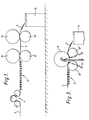
- a sliver 2 of ftax which may be about 25,4 cm (10 inches) wide is fed between a set of three feed rollers 4 so as to enter the frame at for example, a weight of about 150 grams per metre.
- the sliver then passes through a standard faller bed 6 and the sliver then passes between the nip of two drafting or delivery rollers 8, 8'.
- the lower roller 8' is a steel driven roller and the surface of the upper pressing roller 8 is of rubber, having a shore hardness of 75 on the A scale.
- rollers 8, 8' are rotated at about ten times the speed of the feed rollers 4 to produce a draft of ten.
- the lower roller 8' is a steel driven roller and the upper pressing roller 8 is of rubber.
- the sliver is then fed in a relaxed condition without further drafting to a further pair of "splitting" rollers 10, 10' located downstream of the delivery rollers 8.
- the lower splitting roller 10' is driven and the upper roller 10 may be wooden or may be of a very hard rubber or plastic or Tufnol or indeed iron or steel. Alternatively it has been found that it may even be of the same rubber as the drafting roller.
- the fibres are split as they pass between the splitting rollers and the sliver of weight of about 15 grams per metre is fed into a standard can 12.
- the set of splitting rollers however comprises three rollers 10, namely, two lower driven rollers 10' and 10", and a single top or pressing roller 10, which is cradled between the two bottom rollers to create two nips so that the splitting action is enhanced and/or the life of the top roller 10 may be extended due to the reduction in pressure applied to it and/or by the better distribution of the pressure between the top roller and the bottom roller 2.
- An additional roller 8" is positioned downstream of the bottom drafting roller 8' with a pressing roller 8 cradled between them.
- the material is drafted between the nip of the bottom drafting roller 8' and the pressing roller 8 and then splitting is effected between the nip of the additional bottom roller 8" and the pressing roller 8.
- Any suitable pressure arrangement as diagrammatically illustrated, in which load is applied through a pivoted arm 14, may be employed. By alternating the direction of pull on the pressing roller, as illustrated by the alternative position of the arm 14, shown in dash lines, concentration of load towards either of the bottom rollers, or equally between the two, may be effected.
- the pressing roller may be of wood or any other suitable material including rubber.
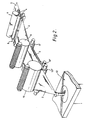
- a plurality (e.g. four) of narrower slivers may be fed in, side by side, and delivered into the same number of cans from standard coiler heads at the front.
Landscapes
- Engineering & Computer Science (AREA)
- Mechanical Engineering (AREA)
- Textile Engineering (AREA)
- General Engineering & Computer Science (AREA)
- Spinning Or Twisting Of Yarns (AREA)
- Preliminary Treatment Of Fibers (AREA)
Claims (6)
Applications Claiming Priority (3)
| Application Number | Priority Date | Filing Date | Title |
|---|---|---|---|
| GB08318222A GB2142985B (en) | 1983-07-05 | 1983-07-05 | Impeller for a double inlet centrifugal fan |
| GB8318322 | 1983-07-06 | ||
| GB838318322A GB8318322D0 (en) | 1983-07-06 | 1983-07-06 | Drawing frames |
Publications (2)
| Publication Number | Publication Date |
|---|---|
| EP0131409A1 EP0131409A1 (fr) | 1985-01-16 |
| EP0131409B1 true EP0131409B1 (fr) | 1987-12-23 |
Family
ID=26286546
Family Applications (1)
| Application Number | Title | Priority Date | Filing Date |
|---|---|---|---|
| EP19840304297 Expired EP0131409B1 (fr) | 1983-07-05 | 1984-06-25 | Train d'étirage |
Country Status (1)
| Country | Link |
|---|---|
| EP (1) | EP0131409B1 (fr) |
Families Citing this family (1)
| Publication number | Priority date | Publication date | Assignee | Title |
|---|---|---|---|---|
| US11104601B2 (en) | 2016-03-17 | 2021-08-31 | Corning Incorporated | Bendable electronic device modules, articles and bonding methods of making the same |
Family Cites Families (11)
| Publication number | Priority date | Publication date | Assignee | Title |
|---|---|---|---|---|
| US1342714A (en) * | 1918-08-02 | 1920-06-08 | Hall H Holdaway | Machine for extracting fiber from palms and the like |
| GB318485A (fr) * | 1928-09-03 | 1930-07-17 | Saechsische Maschinenfabrik | |
| FR660105A (fr) * | 1928-09-08 | 1929-07-08 | Appareil pour séparer des fibres de plantes textiles, et autres fibres adhérentes | |
| FR687122A (fr) * | 1929-12-23 | 1930-08-05 | Perfectionnements dans les machines à étirer les matières textiles | |
| US2107818A (en) * | 1935-05-28 | 1938-02-08 | Elzer Johann | Textile drafting apparatus |
| FR823969A (fr) * | 1936-07-06 | 1938-01-29 | Fairbairn Lawson Combe Barbour | Appareil décortiqueur pour obtenir des fibres à l'aide des feuilles d'agavées et plantes analogues |
| DE689642C (de) * | 1938-12-10 | 1940-03-29 | E H Emil Gminder Dr Ing | Vorrichtung zum fortlaufenden Foerdern von Bastfaserstengeln durch ein Brechwerk |
| CH433071A (de) * | 1965-01-21 | 1967-03-31 | Osaka Kiko Kabushiki Kaisha | Vorrichtung zum Trennen von Fasern |
| GB1091038A (en) * | 1966-04-14 | 1967-11-15 | Textilipari Ki | Improvements in and relating to sliver drafting machines |
| FR2145411B1 (fr) * | 1969-12-05 | 1974-03-29 | Sant Andrea Novara Officine | |
| DE2106815A1 (en) * | 1970-02-20 | 1971-08-26 | Imperial Chemical Industries Ltd London | Drawing polyester staple fibre tows of - different length into untwisted yarns |
-
1984
- 1984-06-25 EP EP19840304297 patent/EP0131409B1/fr not_active Expired
Also Published As
| Publication number | Publication date |
|---|---|
| EP0131409A1 (fr) | 1985-01-16 |
Similar Documents
| Publication | Publication Date | Title |
|---|---|---|
| US2896269A (en) | Multi-drawing frame particularly adapted for use on high-speed spinning frames | |
| US3913176A (en) | Apparatus for the draft and breaking of synthetic textile fibres | |
| US2471057A (en) | Method and apparatus for drafting textile fibers | |
| US2588420A (en) | Textile drafting mechanism | |
| EP0131409A1 (fr) | Train d'étirage | |
| US2686939A (en) | Drawing frame or system comprising an endless belt for conveying the fibrous material in slubbing, roving, and spinning frames | |
| US2304885A (en) | Yarn drafting process | |
| US2323882A (en) | Drafting mechanism for roving frames | |
| GB2142942A (en) | Drawing frames | |
| US5638580A (en) | Method of spinning all-wool yarn on cotton system | |
| ES451805A1 (es) | Maquinas para reducir las fibras o para mezclar, desfieltraro calibrar las cintas de fibras naturales o artificiales. | |
| US2645822A (en) | Drafting textile fibers | |
| US2713701A (en) | Device for producing laps from card slivers on sliver-lap machines | |
| US3657773A (en) | Apparatus for blending fibers | |
| US3331104A (en) | High speed drafting apparatus | |
| US3141203A (en) | Method and means for clearing textile rolls | |
| US3337923A (en) | Method of feeding strands to textile machines | |
| EP1809795B1 (fr) | Ensemble de remettage et procede de remettage d'une toile | |
| US4083085A (en) | Apparatus for blending and paralleling textile fibers | |
| EP3580379B1 (fr) | Procédé et installation de traitement de fibres | |
| US3685102A (en) | Method for processing sliver | |
| US1297794A (en) | Spinning-frame. | |
| US1804968A (en) | Manufacture of yarn | |
| US1766864A (en) | Double-draft arrangement for spinning flax, jute, and similar fiber | |
| US2568502A (en) | Drafting apparatus |
Legal Events
| Date | Code | Title | Description |
|---|---|---|---|
| PUAI | Public reference made under article 153(3) epc to a published international application that has entered the european phase |
Free format text: ORIGINAL CODE: 0009012 |
|
| AK | Designated contracting states |
Designated state(s): BE CH DE FR IT LI |
|
| 17P | Request for examination filed |
Effective date: 19850618 |
|
| 17Q | First examination report despatched |
Effective date: 19860414 |
|
| D17Q | First examination report despatched (deleted) | ||
| GRAA | (expected) grant |
Free format text: ORIGINAL CODE: 0009210 |
|
| AK | Designated contracting states |
Kind code of ref document: B1 Designated state(s): BE FR IT |
|
| ITF | It: translation for a ep patent filed | ||
| ET | Fr: translation filed | ||
| PLBE | No opposition filed within time limit |
Free format text: ORIGINAL CODE: 0009261 |
|
| STAA | Information on the status of an ep patent application or granted ep patent |
Free format text: STATUS: NO OPPOSITION FILED WITHIN TIME LIMIT |
|
| 26N | No opposition filed | ||
| PGFP | Annual fee paid to national office [announced via postgrant information from national office to epo] |
Ref country code: FR Payment date: 19900613 Year of fee payment: 7 |
|
| PGFP | Annual fee paid to national office [announced via postgrant information from national office to epo] |
Ref country code: BE Payment date: 19900709 Year of fee payment: 7 |
|
| ITTA | It: last paid annual fee | ||
| PG25 | Lapsed in a contracting state [announced via postgrant information from national office to epo] |
Ref country code: BE Effective date: 19910630 |
|
| BERE | Be: lapsed |
Owner name: JAMES MACKIE & SONS LTD Effective date: 19910630 |
|
| PG25 | Lapsed in a contracting state [announced via postgrant information from national office to epo] |
Ref country code: FR Effective date: 19920228 |
|
| REG | Reference to a national code |
Ref country code: FR Ref legal event code: ST |