EP0131425B1 - Connecteur modulaire pour terminer un conducteur protégé contre les interférences électromagnétiques et de fréquence radio et cordon ainsi terminé - Google Patents
Connecteur modulaire pour terminer un conducteur protégé contre les interférences électromagnétiques et de fréquence radio et cordon ainsi terminé Download PDFInfo
- Publication number
- EP0131425B1 EP0131425B1 EP84304557A EP84304557A EP0131425B1 EP 0131425 B1 EP0131425 B1 EP 0131425B1 EP 84304557 A EP84304557 A EP 84304557A EP 84304557 A EP84304557 A EP 84304557A EP 0131425 B1 EP0131425 B1 EP 0131425B1
- Authority
- EP
- European Patent Office
- Prior art keywords
- cord
- housing
- plug connector
- modular plug
- receiving cavity
- Prior art date
- Legal status (The legal status is an assumption and is not a legal conclusion. Google has not performed a legal analysis and makes no representation as to the accuracy of the status listed.)
- Expired
Links
- 239000004020 conductor Substances 0.000 claims description 81
- 238000004873 anchoring Methods 0.000 claims description 50
- 230000007704 transition Effects 0.000 claims description 4
- 230000000149 penetrating effect Effects 0.000 claims 1
- 238000010276 construction Methods 0.000 description 14
- 229910052782 aluminium Inorganic materials 0.000 description 10
- XAGFODPZIPBFFR-UHFFFAOYSA-N aluminium Chemical compound [Al] XAGFODPZIPBFFR-UHFFFAOYSA-N 0.000 description 10
- 239000011888 foil Substances 0.000 description 10
- 230000005855 radiation Effects 0.000 description 10
- 238000004519 manufacturing process Methods 0.000 description 7
- 238000004891 communication Methods 0.000 description 6
- 239000004033 plastic Substances 0.000 description 6
- 229920003023 plastic Polymers 0.000 description 6
- 229910000906 Bronze Inorganic materials 0.000 description 4
- OAICVXFJPJFONN-UHFFFAOYSA-N Phosphorus Chemical compound [P] OAICVXFJPJFONN-UHFFFAOYSA-N 0.000 description 4
- 239000010974 bronze Substances 0.000 description 4
- KUNSUQLRTQLHQQ-UHFFFAOYSA-N copper tin Chemical compound [Cu].[Sn] KUNSUQLRTQLHQQ-UHFFFAOYSA-N 0.000 description 4
- 230000000694 effects Effects 0.000 description 4
- PCHJSUWPFVWCPO-UHFFFAOYSA-N gold Chemical compound [Au] PCHJSUWPFVWCPO-UHFFFAOYSA-N 0.000 description 4
- 239000010931 gold Substances 0.000 description 4
- 229910052737 gold Inorganic materials 0.000 description 4
- 238000003780 insertion Methods 0.000 description 4
- 230000037431 insertion Effects 0.000 description 4
- 238000009413 insulation Methods 0.000 description 4
- 239000000463 material Substances 0.000 description 3
- 238000000034 method Methods 0.000 description 3
- 238000005192 partition Methods 0.000 description 3
- 229920002799 BoPET Polymers 0.000 description 2
- 239000005041 Mylar™ Substances 0.000 description 2
- 239000004952 Polyamide Substances 0.000 description 2
- 239000004793 Polystyrene Substances 0.000 description 2
- 229920000122 acrylonitrile butadiene styrene Polymers 0.000 description 2
- 230000015572 biosynthetic process Effects 0.000 description 2
- 239000003989 dielectric material Substances 0.000 description 2
- 229920001971 elastomer Polymers 0.000 description 2
- 239000000806 elastomer Substances 0.000 description 2
- 238000010348 incorporation Methods 0.000 description 2
- 238000001746 injection moulding Methods 0.000 description 2
- 229910052751 metal Inorganic materials 0.000 description 2
- 239000002184 metal Substances 0.000 description 2
- 229920002647 polyamide Polymers 0.000 description 2
- 229920000515 polycarbonate Polymers 0.000 description 2
- 239000004417 polycarbonate Substances 0.000 description 2
- 229920000728 polyester Polymers 0.000 description 2
- 229920000642 polymer Polymers 0.000 description 2
- 229920002223 polystyrene Polymers 0.000 description 2
- 239000000356 contaminant Substances 0.000 description 1
- 238000005516 engineering process Methods 0.000 description 1
- 239000007769 metal material Substances 0.000 description 1
- 230000035515 penetration Effects 0.000 description 1
- 230000002093 peripheral effect Effects 0.000 description 1
- 238000000926 separation method Methods 0.000 description 1
- 239000007787 solid Substances 0.000 description 1
Images



Classifications
-
- H—ELECTRICITY
- H01—ELECTRIC ELEMENTS
- H01R—ELECTRICALLY-CONDUCTIVE CONNECTIONS; STRUCTURAL ASSOCIATIONS OF A PLURALITY OF MUTUALLY-INSULATED ELECTRICAL CONNECTING ELEMENTS; COUPLING DEVICES; CURRENT COLLECTORS
- H01R13/00—Details of coupling devices of the kinds covered by groups H01R12/70 or H01R24/00 - H01R33/00
- H01R13/648—Protective earth or shield arrangements on coupling devices, e.g. anti-static shielding
- H01R13/658—High frequency shielding arrangements, e.g. against EMI [Electro-Magnetic Interference] or EMP [Electro-Magnetic Pulse]
- H01R13/6581—Shield structure
-
- H—ELECTRICITY
- H01—ELECTRIC ELEMENTS
- H01R—ELECTRICALLY-CONDUCTIVE CONNECTIONS; STRUCTURAL ASSOCIATIONS OF A PLURALITY OF MUTUALLY-INSULATED ELECTRICAL CONNECTING ELEMENTS; COUPLING DEVICES; CURRENT COLLECTORS
- H01R13/00—Details of coupling devices of the kinds covered by groups H01R12/70 or H01R24/00 - H01R33/00
- H01R13/58—Means for relieving strain on wire connection, e.g. cord grip, for avoiding loosening of connections between wires and terminals within a coupling device terminating a cable
-
- H—ELECTRICITY
- H01—ELECTRIC ELEMENTS
- H01R—ELECTRICALLY-CONDUCTIVE CONNECTIONS; STRUCTURAL ASSOCIATIONS OF A PLURALITY OF MUTUALLY-INSULATED ELECTRICAL CONNECTING ELEMENTS; COUPLING DEVICES; CURRENT COLLECTORS
- H01R24/00—Two-part coupling devices, or either of their cooperating parts, characterised by their overall structure
- H01R24/60—Contacts spaced along planar side wall transverse to longitudinal axis of engagement
- H01R24/62—Sliding engagements with one side only, e.g. modular jack coupling devices
Definitions
- This invention relates generally to electrical connectors for terminating cords and, more particularly, to so-called modular plug connectors currently being utilized in the telephone and data communications industries as well as in other applications.
- Modular plug connectors are generally used to terminate both flat and round cords.
- a flat cord has a multiplicity of insulated conductors arranged in a spaced linear array within an outer jacket
- a round cord has a multiplicity of insulated conductors arranged in a spiral array within an outer jacket.
- Various configurations of such connectors are disclosed in several patents assigned to Western Electric Company, Inc., such for example as U.S. Patents 3,699,498 issued October 17, 1972; 3,761,869 issued September 25, 1973; 3,860,316 issued January 14, 1975; and 3,954,320 issued May 4, 1976.
- Another advantageous configuration of a modular plug connector is illustrated in U.S. Patent No.
- a modular plug connector generally includes a housing formed of dielectric material and which defines an internal cord receiving cavity into which the end of a cord is inserted through a cord-receiving aperture formed at one of the housing ends.
- the cord-receiving cavity includes a jacket-receiving portion adjacent the aperture and a communicating conductor-receiving portion into which the individual insulated conductors, from which the outer jacket has been stripped, are received.
- a plurality of flat contact terminals, corresponding in number to the number of conductors of the cord, are inserted into individual slots defined in the housing, each terminal being aligned with and electrically engaging a respective conductor.
- the conductors are generally of tinsel, stranded or solid construction while the terminals have blade-like portions which engage respective conductors in a solderless connection.
- the flat terminals have edges which are exposed externally of the housing for engagement with respective aligned wire contact elements provided in a jack receptacle.
- the cord end is secured to the connector by jacket anchoring and strain relief portions integrally hinged with the housing and movable against the cord so as to prevent separation of the connector from the cord during customer use as well as to provide strain-relief facilities for the conductors and jacket.
- Modular plug connectors of the type described above are finding increased use in terminating multi-conductor cords through which digital information is transmitted.
- modular plug connectors are finding increased use in terminating multi-conductor cordage used in home and office computers for connecting the computers with peripheral components, in data communication applications generally, in electronic games, in telephone communication networds and in similar digital applications.
- shielding in the form of a continuous sheath of conductive material between the outer insulation jacket of the cord and the insulated conductors, the shield surrounding and enclosing the conductors along their length.
- the shield can be formed of any suitable conductive material. such as aluminum foil having a thickness of about 0,008mm (0.3 )applied to treated Mylar (R) having a thickness of about 0,025mm (1) or aluminum foil alone. Shields formed of braided metallic material have also been used in this connection. The shield acts to suppress or contain the interference-causing electro-magnetic and radio frequency signals radiating outwardly from the conductors and, conversely, to prevent such high frequency signals radiated from external equipment from causing interference in the conductors.
- drain wire When a shielded cord of the type described above is terminated by a modular plug connector, a so-called “drain wire” has conventionally been employed to ground the shield.
- the drain wire extends through the cord in electrical engagement with the conductive shield and is grounded by passing its end out of the connector and connecting it to a grounded terminal. In this manner, the shield is in effect terminated so that high frequency signals and any electrostatic charge conducted through the shield are "drained", i.e., grounded to thereby control the radiation or discharge thereof.
- one object of the present invention is to provide a new and improved modular plug connector for terminating EMI/RFI shielded cordage.
- Another object of the present invention is to provide a new and improved modular plug connector for terminating EMI/RFI shielded cordage which effectively controls the radiation of high frequency signals from the region at which the modular plug connector is inserted in the jack socket and which protects the cordage from high frequency signals radiated by extraneous equipment.
- Still another object of the present invention is to provide a new and improved modular plug connector for terminating EMI/RFI shielded cordage wherein the modular plug connector itself incorporates means for terminating the EMI/RFI shield.
- Yet another object of the present invention is to provide a new and improved modular plug connector for terminating EMI/RFI shielded cordage which is easy to manufacture and is reliable in operation.
- a further object of the present invention is to provide a new and improved modular plug connector for terminating EMI/RFI shielded cordage which will effectively drain electrostatic charge from the shield without the danger of damaging internal circuitry.
- cord shield terminating means extending through the housing of the modular plug connector wherein respective outer and inner portions of the shield terminating means extend exteriorly of the housing and into the region of the cord receiving cavity defined therein, respectively.
- the shield terminating means comprise conductive means adapted to reliably electrically engage with an exposed area of the shield sheath when the end of the cord is secured to the modular connector.
- the outer portion of the shield terminating means electrically engages a grounded contact suitably provided in the socket so that the EMI, RFI and electrstatic voltage (ESV) conducted through the shield sheath is conducted to ground thereby preventing the radiation or leakage of EMI and RFI through the spaces between the connector and the jack socket and which prevents discharge of the electrostatic voltage.
- ESV electrstatic voltage
- the housing of the modular plug connector is formed of a dielectric material and has walls which define a cord receiving cavity therein into which the end of a flat cord is insertable.
- the cavity includes a conductor-receiving portion adapted to receive through a cord-receiving aperture a plurality of conductors extending from the end of a shielded cord from which the jacket has been stripped and a jacket-receiving portion adapted to receive the jacketed portion of the cord adjacent the conductors.
- the conductors are respectively located within parallelly extending troughs formed in the conductor-receiving portion of the cavity which themselves respectively communicate with aligned openings or slots formed in the housing adapted to receive flat contact terminals which electrically couple with the respective conductors.
- At least one and preferably two anchoring members extend transversely across the housing in respective openings which communicate with the cord-receiving cavity and which are integrally connected to the housing through a plastic hinge and a severable web extending between opposed transverse edges of the anchoring members and adjacent walls of the respective openings.
- the anchoring members each include a surface adapted to engage the cord upon suitable tools urging the same inwardly towards the cord receiving cavity.
- a passage is formed through a side wall of the housing opening at the housing exterior and into the cord-receiving cavity.
- a contact formed of a suitably conductive material is situated in the passage so that an outer portion thereof is exposed at the exterior of the housing and so that an inner portion of the contact extends to at least a slight extent into the cord-receiving cavity, preferably in alignment with one of the anchoring members of the housing.
- the shielded cord is inserted into the cord-receiving cavity such that an area of the shield sheath from which the outer cord jacket has been stripped overlies the inner portion of the contact.
- the aligned anchoring member when moved into the cord-receiving cavity, forces the exposed shield sheath against the inner portion of the contact to provide a secure electrical engagement therewith.
- the jack is provided with a suitable ground contact which engages the outer portion of the contact when the connector is inserted into the jack socket to lead the EMI. RFI and ESV from the shield to ground and thereby prevent leakage from the connector.
- the cord shield terminating means are constituted by an open passage formed in the housing providing clear communication between the cord-receiving cavity and the exterior of the connector.
- the opening is positioned and sized to receive, upon insertion of the connector into the socket, a ground jack contact which engages the shield sheath.
- a shield terminating contact pin is accommodated within a passage formed through a region of a side wall of the connector, opening at one end exteriorly of the housing and at its other end in an open region of the cord- receiving cavity to facilitate manufacture of the connector and at a position wherein the shield will electrically engage the contact pin when the cord is terminated.
- the contact pin accommodating passage is formed through a side wall of the modular plug connector at a region whereby it fully opens into an upper region of the cord-receiving cavity at a location so that the shield will be forcefully urged into electrical engagement with the contact pin situated in the passage when the cord is terminated.
- the contact pin accommodating passage opens into a fully open cavity and the manufacturing problems inherent in the previously suggested embodiments as discussed above are eliminated.
- the outer exposed head of the contact pin electrically engages a grounded member, such as a jack contact, so that high frequency signals and any electrostatic charge conducted through the shield are conducted to ground thereby controlling the radiation of electromagnetic and radio frequency signals.
- Fig. 1 is a perspective view of a modular plug connector housing constructed in accordance with one embodiment of the present invention
- Fig. 2 is a longitudinal section view taken along line 2-2 of Fig. 1;
- Fig. 3 is a transverse section view taken along line 3-3 of Fig. 2 with the shielded cord inserted within the cord-receiving cavity and prior to the securement of the cord within the housing;
- Fig. 4 is a longitudinal section view of a modular plug connector according to the present invention incorporating the housing of Fig. 2 with the shielded cordage inserted within the cord-receiving cavity and wherein the anchoring members of the connector having just been moved by illustrated tooling to secure the cord within the cavity;
- Fig. 5 is a section view taken along line 5-5 of Fig. 4;
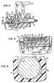
- Fig. 6 is an enlarged section view of the particular conductive shield terminating means constituting a component of the embodiment of the modular plug connector of Figs. 1-5;
- Fig. 7 is a perspective view of another embodiment of a modular plug connector housing in accordance with the present invention.
- Fig. 8 is a section view taken along line 8-8 of Fig. 7 and illustrating the completed connector inserted within a jack socket;
- Fig. 9 is a perspective view of still another embodiment of a modular plug connector housing in accordance with the invention and showing another form of the conductor shield terminating means inserted in position;
- Fig. 10 is a section view taken along line 10-10 of Fig. 9 with the shielded cord secured within the connector;
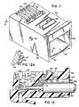
- Fig. 11 is a perspective schematic view of a modular plug connector housing constructed in accordance with the present invention.
- Fig. 12 is a longitudinal section view taken along line 2-2 of Fig. 1 and illustrating the end of a shielded multi-conductor cord inserted within the cord-receiving cavity of the connector housing with a portion of the shield being exposed;
- Fig. 12A is an enlarged detail view of the portions of the shield and contact pin shown in the area designated A in Fig. 2;
- Fig. 13 is a longitudinal section view of a modular plug connector incorporating the housing shown in Figs. 1 and 2 shown after termination of the inserted cord;
- Fig. 14 is a section view taken along line 4-4 of Fig.3;
- Fig. 15 is a section view taken along line 5-5 of Fig.3;
- Fig. 16 is a section view of the modular plug connector inserted into the receptacle of a jack provided with a grounded contact for electrically engaging the shield terminating contact pin of the modular plug connector.
- a modular plug connector housing generally designated 10 which has been improved in accordance with the present invention through the incorporation of means for terminating a cord shield, generally designated 12. It is understood that the construction of the housing per se and the connector of which it forms a part are substantially conventional and known to those skilled in the art as that type of modular plug connector finding greatly increasing use not only in connection with the telephone industry but also in virtually all data communication areas.
- housing 10 of the modular plug connector will be briefly described. It is again noted that such construction is conventional and in this connection reference is made to the above-mentioned U.S. Patent 4,211,462 of Stewart Stamping Corporation which describes this housing construction in greater detail and the disclosure of said patent is hereby incorporated by reference herein. It is of course understood that the invention is not limited to the particular construction of the housing shown and described.
- the housing 10 is a rigid unipartite member formed of a suitable dielectric by conventional injection molding techniques.
- the housing 10 may be made of materials such, for example, as polycarbonate, polyamide, polystyrene, or polyester elastomers or related polymers such as ABS resin.
- the housing 10 has a closed forward free end 14, a cord receiving rearward end 16 and a terminal-receiving side 18 for receiving flat contact terminals 20 (Fig. 4).
- the housing 10 defines a longitudinally extending cord-receiving cavity 22 which externally opens through a cord-receiving aperture 24 formed in the rearward end 16 of housing 10.
- the cord-receiving cavity includes a forward conductor-receiving portion 26 and a rearward enlarged jacket-receiving portion 28.
- the cavity 22 substantially encloses the entire end section of the cord with the terminal end portions of the conductors (having the jacket stripped there-from) being received in the conductor-receiving portion 26 and the adjacent jacketed portion of the cord being received within the jacket-receiving portion 28. It is important to precisely locate the cord conductors 30 (Fig.
- partitions 32 and upper and lower ridges 34-36 extend through the conductor-receiving portion 26 to guide the end regions of respective conductors 30 into corresponding conductor troughs 37.
- a plurality of parallely spaced, longitudinally extending terminal-receiving slots 38 are formed through the terminal-receiving side 18 of housing 10, each slot 38 being aligned over a respective one of the conductor-receiving troughs 37.
- a pair of inwardly extending shoulders 40 and 42 are situated at about the mid-height of each slot 38.
- Each slot 38 is dimensioned so as to snugly receive a respective flat contact terminal 20 as described below.
- each terminal 20 is constructed of an electrical conductive material, such as gold plated phosphor bronze.
- the terminal 20 has a flat conductor portion including a pair of insulation-piercing tangs 44.
- Each of the terminals are formed with a pair of outwardly extending shoulders 46 and 48.
- the housing 10 is also constructed with means for both securing the connector to the cord and for providing strain relief for the jacket and conductors.
- a jacket anchoring member 50 is integrally connected to housing 10 through a plastic hinge 52 (Fig.2) and initially by a frangible portion 54 which supports the jacket anchoring member 50 in its initial position shown in Fig. 2 when a cord is receivable within cavity 22.
- the frangible portion 54 is constructed so as to shear upon the application of an inwardly directed force thereon by a suitable tool so that the jacket anchoring member can pivot about hinge 52 to engage the cord jacket.
- a conductor-anchoring member 56 is formed forwardly of the jacket-anchoring member 50 and extends transversely over the entire width of the conductor-receiving portion 26 of cavity 22.
- the conductor-anchoring member 56 is integrally connected to the housing 10 along its forward and rearward sides.
- the surfaces of the jacket and conductor anchoring members 50 and 56 may be formed with a plurality of parallel concave channels 58 and 60 respectively which advantageously enhance the securement of the cord in the housing as described in U.S. Patent 4,211,462.
- a typical assembly of the modular plug connector and securement to a cord will be described.
- the end of a cord 58 which is shielded in a manner described below, is inserted through aperture 24 into the cord-receiving cavity 22 of housing 10.
- a certain length of the jacket 60 is stripped from the cord 58 so that as the cord is fully inserted into the cavity 22, respective insulated conductors 30 are separated and guided into respective troughs 37 aligned with respective terminal-receiving slots 38 and such that the conductors pass below the conductor-anchoring member 56.
- Terminals 20 are inserted into respective slots 38 and driven towards the conductors so that the tangs 44 of each terminal 20 penetrate the insulation of each conductor thereby making electrical connection therewith and until the points of the tangs become embedded in the bottom wall 62 and terminal shoulders 56 and 58 engage housing shoulders 40 and 42.
- the jacket and conductor-anchoring members 50 and 56 are driven into the conductor-receiving cavity by means of a suitable tool 64 (Fig. 4).
- the frangible portion 54 shears so that the jacket-anchoring member 50 pivots into engagement with the jacket 60 and cord 58 to provide a reliable mechanical securement of the cord to the connector.
- one of the integral connections of the conductor-anchoring member 56 to the housing is sheared and the conductor-anchoring member moves against the conductors 30 to provide strain relief for the conductors.
- the anchoring members are locked in the cord-engaging positions shown in Fig. 4 by suitable locking structure provided in the housing 10 as described in U.S. Patent 4,211,462.
- the modular plug connector is provided with means for terminating the shielding sheath of a cord so that electromagnetic and radio frequency interference conducted through the shield sheath can be conducted through the connector to a grounded contact in the socket.
- the cord shield terminating means extends through the housing of the modular plug connector such that respective inner and outer portions thereof extend exteriorly of the housing and into the region of the cord-receiving cavity respectively.
- the shielded cord 58 comprises the plurality of insulated conductors 30 within the jacket 60.
- Such shielding is of course conventional.
- the cord shield terminating means is constituted by a contact 68 formed of electrically conductive material, such as gold plated phosphor bronze, which extends through a passage 70 which opens to the housing exterior and into the cord-receiving cavity 22 of the modular plug connector.
- the passage 70 is formed by an opening 70a in a side wall 72 of housing 10, the opening 70a continuing in the form of a channel 70b which extends transversely through the bottom wall 62.
- the transverse channel 70b opens along its length into the cord-receiving cavity 22.
- the opening 70a includes an enlarged diameter portion countersunk within the side wall 72 which receives an enlarged head 68a of the contact 68.
- the contact 68 is in the shape of a pin-type member.
- the diameter of the shank 68b of contact 68 is chosen to be sufficiently large such that when the contact is situated in the passage 70, preferably by an interference fit, an upper cylindrical segment of the contact shank 68b extends above the plane of the bottom wall 62 and protrudes into the cord-receiving cavity 22 as best seen in Fig.6.
- the channel 70b has a longitudinal cross-section defined by a pair of arcuate segments 74 and 76 and a pair of inwardly extnding linear segments 78 forming a throat through which the protruding cylindrical segment of the contact extends.
- This configuration facilitates insertion of the contact 68 into the passage 70 with an interference fit while preventing the shank 68b of contact 68 from working loose from the channel 70b.
- the diameter of the contact shank 68b is chosen so that an upper cylindrical segment thereof protrudes into the cord-receiving cavity and as best seen in Fig. 3, the contact extends to about the mid-region of the transverse dimension of the cord-receiving cavity.
- typical dimensions of the components may , be follows: the diameter D of the contact shank is about 0.8mm (.032 inches) the linear length L of the cylindrical segment of the contact shank which extends or protrudes into the cord-receiving cavity is about 0.6mm(.023 inches) and the height H of the protruding cylindrical segment of the contact is about .004 inches.
- a longitudinal groove 80 (Fig. 1) is formed in the outer surface of the housing side wall 72 and intersects the head 68a of contact 68 for purposes described below.
- the termination of the shielded cord in the manner described above will simultaneously provide a termination of the shielding sheath so that EMI, RFI, and ESV conducted through the shield sheath can be conducted through the modular plug connector to a ground contact in the socket.
- the jacket 60 is stripped from the end of the cord 58 so as to leave a length of the shielded sheath 66 (Fig. 4) at the region of the cord-receiving cavity 22 immediately rearward of the troughs 37 defined by partitions 32 and ridges 34 and 36 overlying the shank 68b of contact 68.
- the sheath rests against the protruding cylindrical segment of the contact shank 68b and is situated beneath the conductor-anchoring member 56.
- the terminals 20 are inserted as described above and the jacket and conductor-anchoring members 50 and 56 are driven to their locking position by the tools 65.
- the downward movement of the conductor-anchoring member 56 not only provides strain relief for the conductors and sheath but additionally serves to force the sheath 66 firmly into engagement with the protruding cylindrical segment of the contact shank 68b thereby insuring a reliable electrical communication between the contact 68 and the sheath 66.
- the modular plug connector is thus secured to the end of the cord and is inserted into the socket 82 of a jack 84 as seen in Fig. 5. It is of course understood that the other end of the cord may be similarly terminated.
- the jack 84 is conventional in that it is provided with a linear array of contacts (not shown) adapted to engage the upper edges of respective contact terminals 20 through the upper regions of slots 38 to effect an electrical connection.
- the jack 85 is also provided with a grounded contact 86 adapted to be received and guided within the groove 80 formed in the side wall 72 as the modular plug connector is inserted into the socket 82. When the modular plug connector has been fully inserted into the socket, the grounding contact 86 engages the head 68a of contact 68.
- the cord shield terminating means 12' is constituted by a strip member 88 formed of an electrically conductive material which extends through a passage 90 which opens to the housing exterior and into the cord-receiving cavity 22 of the modular plug connector.
- the strip member 88 comprises a shank portion 92 having a plurality of barbs 92a formed in its upwardly facing surface and a bent head portion 94 adapted to close the opening 90a of passage 90 and which protrudes somewhat to the exterior of the housing 10'.
- the channel portion 90b of passage 90 which may be shallower than the channel 70b of passage 70, receives the shank portion 92 of the strip member 88.
- the sheath 66 electrically communicates with the strip member 88. Removal of the strip member 88 from the passage 90 is prevented through the penetration of the barbs 92a in the sheath 66. Accordingly, an interference fit is not required in this embodiment.
- the grounded jack contact is adapted to electrically engage the head portion 94 of the strip member 88 when the modular plug connector is inserted into the jack socket.
- the cord shield terminating means 12" comprises an aperture 96 formed in the side wall 98 of the modular plug connector housing 10" which extends through the side wall 98, respective outer and inner ends of the aperture 96 opening exteriorly of the housing and into the region of the cord-receiving cavity defined there, respectively.
- the aperture 96 has a relatively longitudinally elongate configuration and is aligned with a guide groove 80" formed in side wall 98.
- the grounded jack contact designated 100 in Fig. 8 is formed with a bent contact portion 100a which is adapted to be received in and pass through the aperture 96 when the modular plug connector is fully inserted into the jack socket.
- the contact portion 100a of jack contact 100 makes direct electrical contact with the shield sheath 66 to conduct any electromagnetic and radio frequency interference conducted through the sheath to ground.
- this embodiment is somewhat more economical in manufacture than the previously described embodiments, it is not as preferred since the aperture 96 provides access to the cord-receiving cavity through which contaminants may enter.
- housing 110 of the modular plug connector will be briefly described. It is again noted that such construction is conventional and in this connection reference is made to the above-mentioned U.S. Patent 4,211,462 of Stewart Stamping Corporation which described a typical housing construction in greater detail and the disclosure of said patent is hereby incorporated by reference herein. It is of course understood that the invention is not limited to the particular construction of the housing shown and described.
- the housing 110 is a rigid unipartite member formed of a suitable dielectric by conventional injection molding techniques.
- the housing 110 may be made of materials such, for example, as polycarbonate, polyamide, polystyrene, or polyester elastomers or related polymers such as ABS resin.
- the housing 110 has a closed forward free end 114, a cord receiving rearward end 116 and a terminal-receiving side 118 for receiving flat contact terminals 120 (Fig. 13).
- the housing 110 defines a longitudinally extending cord-receiving cavity 122 which externally opens through a cord-receiving aperture 124 formed in the rearward end 116 of housing 110.
- the cord-receiving cavity includes a forward conductor-receiving portion 126 and a rearward enlarged jacket-receiving portion 128.
- the cavity 122 substantially encloses the entire end section of the cord with the terminal end portions of the conductors (having the jacket stripped therefrom) being received in the conductor-receiving portion 126 and the adjacent jacketed portion of the cord being received within the jacket-receiving portion 128.
- a plurality of parallely spaced, longitudinally extending terminal-receiving slots 138 are formed through the terminal-receiving side 118 of housing 110, each slot 138 being aligned over a respective one of the conductor-receiving troughs.
- a pair of inwardly extending shoulders 140 and 142 are situated at about the mid-height of each slot 138.
- Each slot 138 is dimensioned so as to snugly receive a respective flat contact terminal 120 as described below.
- each terminal 120 is constructed of an electrical conductive material, such as gold plated phosphor bronze.
- the terminal 120 has a flat conductor portion including a pair of insulation-piercing tangs 144.
- Each of the terminals are formed with a pair of outwardly extending shoulders 146 and 148.
- the housing 110 is also constructed with means for both securing the connector to the cord and for providing strain relief for the jacket and conductors.
- a jacket anchoring member 150 is integrally connected to housing 110 through a plastic hinge 152 and initially by a frangible portion 154 (Fig. 12) which supports the jacket anchoring member 150 in its initial position shown in Fig. 2 when a cord is receivable within cavity 122.
- the frangible portion 154 is constructed so as to shear upon the application of an inwardly directed force thereon by a suitable tool so that the jacket anchoring member can pivot about hinge 152 to engage the cord jacket.
- a conductor-anchoring member 156 is formed forwardly of the jacket-anchoring member 150 and extends transversely over the entire width of the conductor-receiving portion 126 of cavity 122.
- the conductor-anchoring member 156 is integrally connected to the housing 110 along its forward and rearward sides.
- the surfaces of the jacket and conductor anchoring members 150 and 156 may be formed with a plurality of parallel concave channels 158 and 160 respectively which advantageously enhance the securement of the cord in the housing as described in U.S. Patent 4,211,462.
- a typical assembly of the modular plug connector and securement to a cord will be described.
- the end of a cord 113 which is shielded in a manner described below, is inserted through aperture 124 into the cord-receiving cavity 122 of housing 110.
- a certain length of the jacket 166 is stripped from the cord 113 so that as the cord is fully inserted into the cavity 122, respective insulated conductors 130 are separated and guided into respective troughs aligned with respective terminal-receiving slots 138 and such that the conductors become situated below the conductor-anchoring member 156 and the cord jacket becomes situated below the jacket anchoring member 150.
- Terminals 120 are inserted into respective slots 138 and driven towards the conductors so that the tangs 144 of each terminal 120 penetrate the insulation of each conductor thereby making electrical connection therewith and until the points of the tangs become embedded in the bottom wall 162 and terminal shoulders 156 and 158 engage housing shoulders 140 and 142.
- the jacket and conductor-anchoring members 150 and 156 are driven downwardly by means of a suitable tool 162.
- the frangible portion 154 shears so that the jacket-anchoring member 150 pivots into engagement with the jacket 166 of cord 158 to provide a reliable mechanical securement of the cord to the connector.
- one of the web-like portions connecting the conductor-anchoring member 156 to the housing is sheared and the conductor-anchoring member moves against the conductors 130 to provide strain relief for the conductors.
- the anchoring members are locked in the cord-engaging positions shown in Fig. 14 by suitable conventional locking structure.
- the modular plug connector is provided with means for terminating the EMI/RFI shield of a cord as a part of the connector itself so that electromagnetic and radio frequency interference-causing signals conducted through the shield can be conducted through the connector to a grounded contact in a jack.
- the housing 110 in accordance with the invention is molded so that the downwardly facing surface 170 of cord-receiving cavity 122 in the region of the transition between the conductor and jacket-receiving portions 126 and 128 has a substantially quarter-cylindrical surface segment 172.
- the cylindrical surface segment 172 forms a bearing surface for the shank 174 of the shield terminating contact pin 176.
- a circular opening 178 is formed in a side wall 180 of housing 110 coaxial with the cylindrical surface segment 172 and having a radius substantially equal to the radius of curvature of the cylindrical surface segment 172.
- the opening 178 opens at one end exteriorly of the housing and at its other end in an open region of the cord-receiving cavity 122 thereby facilitating its formation without pieces of plastic which are cut from the housing during formation passing into the cord-receiving cavity.
- the contact pin 176 is formed of electrically conductive material, such as gold plated phosphor bronze.
- Contact pin 176 includes the cylindrical shank 174 having a radius substantially equal or slightly smaller than the radius of opening 178 and the radius of curvature of the cylindrical surface segment 172, and an enlarged disc-shaped head 182 at one end of the shank 174.
- the other end of the shank 174 is passed through the circular opening or passage 178 in housing side wall 180 until the head 182 abuts against the outer surface of side wall 180. It will be understood that a segment of the surface of the contact pin shank 174 will be contiguous with the cylindrical surface segment 172 of the downwardly facing surface 170 of cord-receiving cavity 122 as seen in the figures. The contact pin will be held in this position through its engagement within the passage 178.
- the cord 113 in the illustrated embodiment includes a plurality of insulated conductors 130 surrounded by a shield constituted by a sheath of aluminum foil 184 (Fig. 12A) applied to a sheath of Mylar (R) 186.
- the shield 112 extends along the length of the cord 113 with the aluminum foil 184 next to the conductors 130.
- the end portion of the outer insulation jacket 166 Prior to the insertion of the end of cord 113 into the cord-receiving cavity 122, the end portion of the outer insulation jacket 166 is removed exposing the shield 112.
- the portion of the exposed shield 112 which overlies the conductors 130 is folded back over the outer surface of jacket 166 as seen in Fig. 12 so that the aluminum foil layer 184 is exposed and faces forwardly at the portion in front of the jacket 166.
- the remaining portions of the shield 112 can be removed if desired.
- Locking of the jacket-anchoring member 150 to its locked position as seen in Fig. 13 causes the portion of the jacket 166 situated forwardly thereof to be deformed and flow upwardly to substantially fill the space between the forward jacket contacting surface thereof and the downwardly facing surface 170 of the cord-receiving cavity 122 at the transition between the conductor and jacket receiving portions 126 and 128.
- This forcefully urges the exposed portion of shield 112 against the shank 174 of contact pin 176 to provide an extremely reliable electrical engagement between the aluminum foil layer 184 of the shield and the rearwardly facing surface segment of the shank 174 of contact pin 176 as seen in Figs. 13 and 15.
- a portion of the exposed shield 112 is urged under the force of the jacket-anchoring member 150 underneath the shank 174 as seen in Figs. 13 and 14 to even further enlarge the area of electrical contact between the shield and contact pin.
- the modular plug connector terminating the end of the cord is inserted into the receptacle 188 of a suitable jack 190 provided with a linear array of contact wires (not shown) adapted to engage the upper edges of respective flat contact terminals 120 through the upper regions of slots 138 to effect electrical connections therewith.
- the jack 190 is also provided with a grounded contact 192 adapted to engage the head 182 of contact pin 176 when the modular plug connector is fully inserted within the receptacle 188 to thereby ground the shield 112.
- a channel 194 is formed in receptacle 188 to accommodate the grounded contact 192 and head 182 of contact pin 176.
- the electromagnetic and radio frequency interference-causing signals and any electrostatic charge present in the aluminum foil layer 184 of shield 112 will be conducted through the modular plug connector by the contact pin 176 to the grounded jack contact 192 to ground. In this manner, the possibility of leakage of interference causing signals from the region of the connector is effectively eliminated.
- the manufacture of the modular plug connector in accordance with the invention is facilitated by the provision that the passage or opening 178 opens into a fully opened space within the cord-receiving cavity and, moreover, the electrical contact between the shield and the contact pin is extremely reliable due to the forceful urging of the shield against the contact pin by the cord jacket under the force of the jacket-anchoring member 150.
Landscapes
- Details Of Connecting Devices For Male And Female Coupling (AREA)
- Connections By Means Of Piercing Elements, Nuts, Or Screws (AREA)
- Multi-Conductor Connections (AREA)
- Coupling Device And Connection With Printed Circuit (AREA)
Claims (18)
- Connecteur modulaire pour terminer un cordon protégé ayant un certain nombre de conducteurs isolés enfermés dans une enveloppe externe et une gaine de protection entre l'enveloppe et les conducteurs et renfermant ces derniers sensiblement sur leur longueur, comprenant : un boîtier diélectrique (10, 10', 10", 110) ayant une extrémité avant libre (14, 140) et une extrémité d'entrée du cordon vers l'arrière (16, 16', 16", 116) ayant une ouverture (24, 24', 24", 124) qui y est formée, débouchant dans une cavité (22, 22', 22", 122) de réception du cordon formée dans le boîtier (10, 10', 10", 110), ladite cavité (22, 22', 22", 122) de réception du cordon ayant une portion vers l'avant de réception des conducteurs (26, 126) et une portion vers l'arrière de réception de l'enveloppe (28, 128), un certain nombre de creux parallèles (37) de réception des conducteurs s'étendant en direction longitudinale sur une partie de la portion de réception des conducteurs (26, 126) de ladite cavité (22, 22' , 22", 122), un certain nombre d'ouvertures en forme de fente (38, 38', 38", 138) adaptées à recevoir des bornes plates de contact (20, 120), chacune desdites ouvertures étant alignée et communiquant avec un creux respectif de réception d'un conducteur; caractérisé par un moyen (12, 12,' 12", 112) traversant ledit boîtier (10, 10', 10", 110) pour terminer la gaine de protection du cordon (66, 166) pour qu'ainsi l'interférence électromagnétique et de fréquence radio conduite dans la gaine (66, 166) soit conduite par ledit moyen de terminaison (12, 12', 12", 112) de la gaine de protection à travers ledit boîtier (10, 10' , 10", 110) pour empêcher ou au moins sensiblement réduire la fuite de l'interférence de la région du connecteur modulaire et qu'ainsi la tension électrostatique conduite dans la gaine (66, 166) soit conduite par ledit moyen de terminaison de la gaine de protection (12, 12' , 12", 122) à travers ledit boîtier (10, 10', 10", 110) pour éliminer la possibilité d'une dégradation du montage interne du fait de la formation d'un arc ou d'un court-circuit.
- Connecteur modulaire selon la revendication 1, caractérisé en ce que ledit moyen de terminaison (12) de la gaine de protection du cordon comprend des moyens électriquement conducteurs (68) portés dans une paroi (72) dudit boîtier (10), ayant une portion interne (68b) adaptée à produire un contact électrique avec la gaine (66) de protection du cordon et une portion externe (68a) s'étendant jusqu'à l'extérieur dudit boîtier (10).
- Connecteur modulaire selon la revendication 2, caractérisé en ce que lesdits moyens électriquement conducteurs (68) sont situés dans un passage (70) formé dans ledit boîtier (10), ledit passage (70) débouchant dans ladite cavité (22) de réception du cordon et vers l'extérieur dudit boîtier (10).
- Connecteur modulaire selon la revendication 3, caractérisé en ce que lesdits moyens électriquement conducteurs (68) sont constitués par un contact (68b) qui est formé en un matériel électriquement conducteur, ledit contact (68b) étant situé dans ledit passage (70) avec au moins une partie d'une portion interne dépassant dans ladite cavité (22) de réception du cordon et une partie externe (68a) qui est exposée à l'extérieur dudit boîtier (10).
- Connecteur modulaire selon la revendication 4, caractérisé en ce que ledit passage (70) comprend une ouverture (70a) dans une paroi latérale (72) dudit boîtier et un canal aligné (70b) formé dans une paroi inférieure (62) de ladite cavité (22) de réception du cordon, ledit canal (70b) débouchant à une région de gorge dans ladite cavité (22) de réception du cordon et s'étendant sensiblement transversalement sur au moins une partie de ladite cavité (22) de réception du cordon.
- Connecteur modulaire selon la revendication 5, caractérisé en ce que ledit contact (68b) a une portion de tige sensiblement cylindrique et ou un segment cylindrique de ladite portion de tige traverse ladite région de gorge et dépasse dans ladite cavité (22) de réception du cordon.
- Connecteur modulaire selon la revendication 6, comprenant de plus une gorge longitudinale (80) formée dans ladite paroi latérale (72) du boîtier en alignement avec ladite portion externe (68b) dudit contact.
- Connecteur modulaire selon la revendication 3, caractérisé en ce que ledit boîtier (10) comprend de plus au moins un organe d'ancrage (56) s'étendant transversalement à travers ledit boîtier et qui lui est relié pour un mouvement d'une position de déblocage à une position de blocage où sa surface est placée au moins partiellement dans ladite portion (26) de réception de conducteurs de ladite cavité (22) de réception du cordon, et où ledit passage comprend un canal (70b) formé dans une paroi inférieure (62) de ladite portion (26) de réception de conducteurs, ledit canal (70b) étant placé en relation sensiblement opposée par rapport audit organe d'ancrage (56), ainsi lorsque ledit organe d'ancrage (56) est déplacé à sa position de blocage, il sert à ancrer simultanément les conducteurs dans ledit boîtier et à forcer la gaine (66) en contact électrique sûr avec lesdits moyens électriquement conducteurs (68).
- Connecteur modulaire selon la revendication 1, caractérisé en ce que lesdits moyens de terminaison de la gaine du cordon sont constitués d'un organe formant lame (88) qui est formé en un matériau électriquement conducteur, ledit organe formant lame (88) étant situé dans un passage (90) avec au moins une portion interne (92) qui dépasse dans ladite cavité (22') de réception du cordon et une partie externe (94) qui est exposée à l'extérieur dudit boîtier (10').
- Connecteur modulaire selon la revendication 9, caractérisé en ce que des moyens formant picots (92a) pour pénétrer dans ladite gaine de protection (66) sont prévus sur la portion interne (92) dudit organe formant lame.
- Connecteur modulaire selon la revendication 1, caractérisé en ce que ledit moyen de terminaison de la gaine du cordon (12") comprend une ouverture (96) qui est formée dans une paroi (98) dudit boîtier (10") communiquant entre ladite portion de réception de conducteur de ladite cavité (22") de réception du cordon et l'extérieur dudit boîtier (10").
- Connecteur modulaire selon la revendication 11, caractérisé en ce que ladite ouverture (96) est allongée en direction longitudinale.
- Connecteur modulaire selon la revendication 4, caractérisé en ce que ledit contact (68) comprend un organe en forme de cheville.
- Connecteur modulaire selon la revendication 1, caractérisé en ce qu'une ouverture (178) est formée à travers l'une des parois latérales (180) du boîtier (110), qui débouche à l'une de ses extrémités à la surface extérieure de ladite paroi latérale du boîter et à l'autre de ses extrémités en une région totalement ouverte de la cavité (122) de réception du cordon ; et ledit moyen de terminaison de la gaine du cordon comprend une cheville de contact (176) traversant ladite ouverture (178), ladite cheville de contact (176) ayant une extrémité (182) exposée à la surface extérieure de ladite paroi latérale (180) du boîtier et une tige (174) située dans ladite cavité (122) de réception du cordon adaptée à venir en engagement électrique avec une portion exposée de la gaine condutrice (112) du cordon pour la terminer.
- Connecteur modulaire selon la revendication 14, caractérisé en ce que ladite cavité (122) de réception du cordon comprend une région de transition entre lesdites portions de réception de conducteurs et d'enveloppe (126, 128), ayant une surface (170) tournée vers la cavité (122) de réception de conducteurs et où ladite tige de la cheville de contact (174) est située avec un segment de sa surface contigu avec un segment (172) de ladite surface (170).
- Connecteur modulaire selon la revendication 15, caractérisé en ce que ladite tige (174) de la cheville de contact est cylindrique et en ce que ledit segment contigu (172) de ladite surface (170) de ladite cavité (122) de réception du cordon a une forme cylindrique correspondante.
- Connecteur modulaire selon la revendication 15, caractérisé en ce que ledit boîtier (110) comprend un organe venant de matière (150) d'ancrage de l'enveloppe qui est situé vers l'arrière de ladite région de transition et qui s'étend transversalement à travers ledit boîtier (110) et qui lui est connecté pour un mouvement d'une position de déblocage à une position de blocage, où sa surface est placée au moins partiellement dans ladite portion (128) de réception de l'enveloppe de ladite cavité (122) de réception du cordon.
- Connecteur modulaire selon l'une quelconque des revendications 14 à 17, terminant un cordon protégé, caractérisé par un cordon (113) ayant un certain nombre de conducteurs isolés (130) enfermés dans une enveloppe externe (166) et une protection conductrice (112) entre l'enveloppe (166) et les conducteurs (130) et renfermant ces derniers sur leur longueur ; une portion extrême dudit cordon (113) ayant l'enveloppe (166) qui en est enlevée pour exposer une portion de ladite protection conductrice (112) et desdits conducteurs (130), ladite portion d'extrémité du cordon étant insérée dans ladite cavité (122) de réception du cordon ; chacune desdites bornes plates de contact (120) étant en engagement électrique avec un respectif desdits conducteurs (130) du cordon dans ladite portion (126) de réception de conducteurs dudit boîtier ; et où ladite tige de ladite cheville de contact (176) est en engagement électrique avec ladite portion exposée de ladite protection conductrice (112).
Priority Applications (1)
| Application Number | Priority Date | Filing Date | Title |
|---|---|---|---|
| AT84304557T ATE60960T1 (de) | 1983-07-11 | 1984-07-04 | Modulartiger verbinder fuer den anschluss von gegen elektromagnetische interferenz und radiointerferenz abgeschirmten leitungen und damit angeschlossene schnur. |
Applications Claiming Priority (4)
| Application Number | Priority Date | Filing Date | Title |
|---|---|---|---|
| US512375 | 1983-07-11 | ||
| US06/512,375 US4516825A (en) | 1983-07-11 | 1983-07-11 | Modular connector for terminating EMI/RFI shielded cordage |
| US570805 | 1984-01-16 | ||
| US06/570,805 US4506944A (en) | 1983-07-11 | 1984-01-16 | Modular connector for terminating EMI/RFI shielded cordage and cord terminated thereby |
Publications (3)
| Publication Number | Publication Date |
|---|---|
| EP0131425A2 EP0131425A2 (fr) | 1985-01-16 |
| EP0131425A3 EP0131425A3 (en) | 1987-10-07 |
| EP0131425B1 true EP0131425B1 (fr) | 1991-02-20 |
Family
ID=27057543
Family Applications (1)
| Application Number | Title | Priority Date | Filing Date |
|---|---|---|---|
| EP84304557A Expired EP0131425B1 (fr) | 1983-07-11 | 1984-07-04 | Connecteur modulaire pour terminer un conducteur protégé contre les interférences électromagnétiques et de fréquence radio et cordon ainsi terminé |
Country Status (5)
| Country | Link |
|---|---|
| US (1) | US4506944A (fr) |
| EP (1) | EP0131425B1 (fr) |
| JP (1) | JPH0675413B2 (fr) |
| CA (1) | CA1207857A (fr) |
| DE (1) | DE3484117D1 (fr) |
Cited By (1)
| Publication number | Priority date | Publication date | Assignee | Title |
|---|---|---|---|---|
| US12633685B2 (en) | 2023-11-16 | 2026-05-19 | Hubbell Incorporated | Multi-pole electrical wiring devices with wire termination assemblies |
Families Citing this family (19)
| Publication number | Priority date | Publication date | Assignee | Title |
|---|---|---|---|---|
| US4641901A (en) * | 1984-01-16 | 1987-02-10 | Stewart Stamping Corp. | Printed circuit board jack for modular plug connector terminated cord |
| CA1254275A (fr) * | 1984-07-26 | 1989-05-16 | Ronald Nitowski | Fiche modulaire a huit conducteurs |
| NL8402949A (nl) * | 1984-09-27 | 1986-04-16 | Du Pont Berg Electronics Div | Connector. |
| NL8403432A (nl) * | 1984-11-09 | 1986-06-02 | Du Pont Berg Electronics Div | Steekcontactelement. |
| US4607905A (en) * | 1985-04-18 | 1986-08-26 | Brand-Rex Company | Modular plug |
| US4738638A (en) * | 1986-10-28 | 1988-04-19 | Virginia Plastics Company | Electrical connector with improved integral ground strap for shielded cable |
| US4713023A (en) * | 1987-01-30 | 1987-12-15 | Molex Incorporated | Electrical connector and method of assembly |
| US6561838B1 (en) | 1999-12-13 | 2003-05-13 | Adc Telecommunications, Inc. | Connector plug and insert for twisted pair cables |
| US6290538B1 (en) * | 2000-03-14 | 2001-09-18 | Alan L. Pocrass | RJ type coaxial cable connector with visual indicator |
| USD446186S1 (en) | 2000-12-13 | 2001-08-07 | Dsm&T Co. Inc. | Electrical plug housing |
| US6612856B1 (en) * | 2001-12-17 | 2003-09-02 | 3Com Corporation | Apparatus and methods for preventing cable-discharge damage to electronic equipment |
| US7375284B2 (en) * | 2006-06-21 | 2008-05-20 | Adc Telecommunications, Inc. | Multi-pair cable with varying lay length |
| US9640924B2 (en) | 2014-05-22 | 2017-05-02 | Panduit Corp. | Communication plug |
| US10461444B2 (en) | 2017-01-06 | 2019-10-29 | Hubbell Incorporated | Electrical wiring devices with screwless connection terminals |
| US10164375B1 (en) * | 2018-04-29 | 2018-12-25 | Cheng Uei Precision Industry Co., Ltd. | Plug connector |
| US11495895B2 (en) | 2019-05-01 | 2022-11-08 | Hubbell Incorporated | Terminations for electrical wiring devices |
| MX2024003613A (es) | 2021-09-27 | 2024-04-09 | Hubbell Inc | Terminales de conexion sin tornillos con administrador de cables. |
| WO2023177811A1 (fr) | 2022-03-16 | 2023-09-21 | Hubbell Incorporated | Dispositifs de câblage électrique à bornes de fil sans vis |
| CN120858493A (zh) | 2022-11-16 | 2025-10-28 | 豪倍公司 | 具有线材端接组件的多极电气布线装置 |
Family Cites Families (7)
| Publication number | Priority date | Publication date | Assignee | Title |
|---|---|---|---|---|
| GB948610A (en) * | 1962-05-22 | 1964-02-05 | Marie Harting | Improvements in or relating to electric plugs or sockets |
| US3998514A (en) * | 1975-10-06 | 1976-12-21 | Western Electric Company, Inc. | Device armed with a terminal for making electrical connection with a conductor |
| US4211462A (en) * | 1979-01-22 | 1980-07-08 | Stewart Stamping Corporation, A Division Of Insilco Corp. | Electrical connector for termination cords with improved locking means |
| US4345811A (en) * | 1980-03-27 | 1982-08-24 | Burroughs Corporation | Flat ribbon cable shield |
| US4352531A (en) * | 1980-06-02 | 1982-10-05 | Amp Incorporated | Commoning element for an electrical connector |
| JPS5737900U (fr) * | 1980-08-14 | 1982-02-27 | ||
| US4457575A (en) * | 1982-09-21 | 1984-07-03 | Amp Incorporated | Electrical connector having improved shielding and keying systems |
-
1984
- 1984-01-16 US US06/570,805 patent/US4506944A/en not_active Expired - Lifetime
- 1984-07-04 EP EP84304557A patent/EP0131425B1/fr not_active Expired
- 1984-07-04 DE DE8484304557T patent/DE3484117D1/de not_active Expired - Fee Related
- 1984-07-11 JP JP59142498A patent/JPH0675413B2/ja not_active Expired - Lifetime
- 1984-07-11 CA CA000458652A patent/CA1207857A/fr not_active Expired
Cited By (1)
| Publication number | Priority date | Publication date | Assignee | Title |
|---|---|---|---|---|
| US12633685B2 (en) | 2023-11-16 | 2026-05-19 | Hubbell Incorporated | Multi-pole electrical wiring devices with wire termination assemblies |
Also Published As
| Publication number | Publication date |
|---|---|
| EP0131425A2 (fr) | 1985-01-16 |
| JPH0675413B2 (ja) | 1994-09-21 |
| JPS6047380A (ja) | 1985-03-14 |
| CA1207857A (fr) | 1986-07-15 |
| EP0131425A3 (en) | 1987-10-07 |
| DE3484117D1 (de) | 1991-03-28 |
| US4506944A (en) | 1985-03-26 |
Similar Documents
| Publication | Publication Date | Title |
|---|---|---|
| US4516825A (en) | Modular connector for terminating EMI/RFI shielded cordage | |
| US4767355A (en) | Jack and connector | |
| US4506944A (en) | Modular connector for terminating EMI/RFI shielded cordage and cord terminated thereby | |
| EP0175868B1 (fr) | Prise de courant et connecteur | |
| EP0224200B1 (fr) | Connecteur fiche et douille blindé | |
| US4641901A (en) | Printed circuit board jack for modular plug connector terminated cord | |
| US4533199A (en) | IDC termination for coaxial cable | |
| US4884981A (en) | Shielded data connector | |
| EP0735612B1 (fr) | Connecteur électrique avec support de conducteurs et blindage amélioré | |
| US5059140A (en) | Shielded plug and jack connector | |
| US4451099A (en) | Electrical connector having commoning member | |
| EP0072063B1 (fr) | Connecteur de câble coaxial à deux ou trois rangées | |
| US4556275A (en) | Electrical panelboard connector | |
| US4491381A (en) | Electrical panelboard connector | |
| US5961348A (en) | System for terminating the shield of a high speed cable | |
| US4889503A (en) | Shielded plug and jack connector | |
| US6250959B1 (en) | Connector for coaxial cables with very fine conductors | |
| US6007384A (en) | Casing for a plug for a cable having a drain wire | |
| US11239617B2 (en) | Cable receptacle connector | |
| EP0568273B1 (fr) | Fiche modulaire avec moyens améliorés pour atténuer l'effort de tension sur un câble | |
| EP0243150B1 (fr) | Assemblage pour câble blindé | |
| US4537459A (en) | Jack for EMI/RFI shield terminating modular plug connector | |
| US5564940A (en) | Electrical connector having a conductor holding block | |
| IL111678A (en) | Electrical connector with protective latch | |
| EP0294460A1 (fr) | Connecteur blinde pour transmission de donnees. |
Legal Events
| Date | Code | Title | Description |
|---|---|---|---|
| PUAI | Public reference made under article 153(3) epc to a published international application that has entered the european phase |
Free format text: ORIGINAL CODE: 0009012 |
|
| AK | Designated contracting states |
Designated state(s): AT BE CH DE FR GB IT LI LU NL SE |
|
| PUAL | Search report despatched |
Free format text: ORIGINAL CODE: 0009013 |
|
| AK | Designated contracting states |
Kind code of ref document: A3 Designated state(s): AT BE CH DE FR GB IT LI LU NL SE |
|
| 17P | Request for examination filed |
Effective date: 19880229 |
|
| 17Q | First examination report despatched |
Effective date: 19890908 |
|
| GRAA | (expected) grant |
Free format text: ORIGINAL CODE: 0009210 |
|
| AK | Designated contracting states |
Kind code of ref document: B1 Designated state(s): AT BE CH DE FR GB IT LI LU NL SE |
|
| REF | Corresponds to: |
Ref document number: 60960 Country of ref document: AT Date of ref document: 19910315 Kind code of ref document: T |
|
| REF | Corresponds to: |
Ref document number: 3484117 Country of ref document: DE Date of ref document: 19910328 |
|
| ITF | It: translation for a ep patent filed | ||
| ET | Fr: translation filed | ||
| PGFP | Annual fee paid to national office [announced via postgrant information from national office to epo] |
Ref country code: LU Payment date: 19910626 Year of fee payment: 8 |
|
| PLBE | No opposition filed within time limit |
Free format text: ORIGINAL CODE: 0009261 |
|
| STAA | Information on the status of an ep patent application or granted ep patent |
Free format text: STATUS: NO OPPOSITION FILED WITHIN TIME LIMIT |
|
| EPTA | Lu: last paid annual fee | ||
| 26N | No opposition filed | ||
| PG25 | Lapsed in a contracting state [announced via postgrant information from national office to epo] |
Ref country code: LU Free format text: LAPSE BECAUSE OF NON-PAYMENT OF DUE FEES Effective date: 19920704 |
|
| EAL | Se: european patent in force in sweden |
Ref document number: 84304557.6 |
|
| PGFP | Annual fee paid to national office [announced via postgrant information from national office to epo] |
Ref country code: GB Payment date: 19980610 Year of fee payment: 15 |
|
| PGFP | Annual fee paid to national office [announced via postgrant information from national office to epo] |
Ref country code: SE Payment date: 19980615 Year of fee payment: 15 |
|
| PGFP | Annual fee paid to national office [announced via postgrant information from national office to epo] |
Ref country code: BE Payment date: 19980619 Year of fee payment: 15 |
|
| PGFP | Annual fee paid to national office [announced via postgrant information from national office to epo] |
Ref country code: FR Payment date: 19980625 Year of fee payment: 15 |
|
| PGFP | Annual fee paid to national office [announced via postgrant information from national office to epo] |
Ref country code: AT Payment date: 19980728 Year of fee payment: 15 |
|
| PGFP | Annual fee paid to national office [announced via postgrant information from national office to epo] |
Ref country code: NL Payment date: 19980730 Year of fee payment: 15 |
|
| PGFP | Annual fee paid to national office [announced via postgrant information from national office to epo] |
Ref country code: CH Payment date: 19980812 Year of fee payment: 15 |
|
| PGFP | Annual fee paid to national office [announced via postgrant information from national office to epo] |
Ref country code: DE Payment date: 19980925 Year of fee payment: 15 |
|
| PG25 | Lapsed in a contracting state [announced via postgrant information from national office to epo] |
Ref country code: GB Free format text: LAPSE BECAUSE OF NON-PAYMENT OF DUE FEES Effective date: 19990704 Ref country code: AT Free format text: LAPSE BECAUSE OF NON-PAYMENT OF DUE FEES Effective date: 19990704 |
|
| PG25 | Lapsed in a contracting state [announced via postgrant information from national office to epo] |
Ref country code: SE Free format text: THE PATENT HAS BEEN ANNULLED BY A DECISION OF A NATIONAL AUTHORITY Effective date: 19990705 |
|
| PG25 | Lapsed in a contracting state [announced via postgrant information from national office to epo] |
Ref country code: LI Free format text: LAPSE BECAUSE OF NON-PAYMENT OF DUE FEES Effective date: 19990731 Ref country code: FR Free format text: THE PATENT HAS BEEN ANNULLED BY A DECISION OF A NATIONAL AUTHORITY Effective date: 19990731 Ref country code: CH Free format text: LAPSE BECAUSE OF NON-PAYMENT OF DUE FEES Effective date: 19990731 Ref country code: BE Free format text: LAPSE BECAUSE OF NON-PAYMENT OF DUE FEES Effective date: 19990731 |
|
| BERE | Be: lapsed |
Owner name: STEWART STAMPING CORP. (A CONNECTICUT CORP.) Effective date: 19990731 |
|
| PG25 | Lapsed in a contracting state [announced via postgrant information from national office to epo] |
Ref country code: NL Free format text: LAPSE BECAUSE OF NON-PAYMENT OF DUE FEES Effective date: 20000201 |
|
| GBPC | Gb: european patent ceased through non-payment of renewal fee |
Effective date: 19990704 |
|
| REG | Reference to a national code |
Ref country code: CH Ref legal event code: PL |
|
| EUG | Se: european patent has lapsed |
Ref document number: 84304557.6 |
|
| NLV4 | Nl: lapsed or anulled due to non-payment of the annual fee |
Effective date: 20000201 |
|
| PG25 | Lapsed in a contracting state [announced via postgrant information from national office to epo] |
Ref country code: DE Free format text: LAPSE BECAUSE OF NON-PAYMENT OF DUE FEES Effective date: 20000503 |
|
| REG | Reference to a national code |
Ref country code: FR Ref legal event code: ST |