EP0131448A2 - Dispositif de refroidissement - Google Patents
Dispositif de refroidissement Download PDFInfo
- Publication number
- EP0131448A2 EP0131448A2 EP84304630A EP84304630A EP0131448A2 EP 0131448 A2 EP0131448 A2 EP 0131448A2 EP 84304630 A EP84304630 A EP 84304630A EP 84304630 A EP84304630 A EP 84304630A EP 0131448 A2 EP0131448 A2 EP 0131448A2
- Authority
- EP
- European Patent Office
- Prior art keywords
- air
- chamber
- ducting
- extraction
- cooling
- Prior art date
- Legal status (The legal status is an assumption and is not a legal conclusion. Google has not performed a legal analysis and makes no representation as to the accuracy of the status listed.)
- Withdrawn
Links
- 238000001816 cooling Methods 0.000 title claims abstract description 66
- 238000000605 extraction Methods 0.000 claims abstract description 51
- 238000000034 method Methods 0.000 claims abstract description 14
- 235000015173 baked goods and baking mixes Nutrition 0.000 claims description 14
- 239000000463 material Substances 0.000 claims description 4
- 239000004033 plastic Substances 0.000 claims description 3
- 229920003023 plastic Polymers 0.000 claims description 3
- 238000007599 discharging Methods 0.000 claims description 2
- 230000003134 recirculating effect Effects 0.000 abstract 1
- 238000001035 drying Methods 0.000 description 6
- 230000004580 weight loss Effects 0.000 description 4
- 239000002826 coolant Substances 0.000 description 3
- 238000010586 diagram Methods 0.000 description 3
- 230000000994 depressogenic effect Effects 0.000 description 2
- 230000033001 locomotion Effects 0.000 description 2
- 238000005192 partition Methods 0.000 description 2
- 241000124032 Paracheirodon axelrodi Species 0.000 description 1
- 239000004743 Polypropylene Substances 0.000 description 1
- 235000008429 bread Nutrition 0.000 description 1
- 239000003990 capacitor Substances 0.000 description 1
- 235000009508 confectionery Nutrition 0.000 description 1
- 230000001419 dependent effect Effects 0.000 description 1
- 230000002401 inhibitory effect Effects 0.000 description 1
- 238000004519 manufacturing process Methods 0.000 description 1
- 239000000203 mixture Substances 0.000 description 1
- 230000007935 neutral effect Effects 0.000 description 1
- -1 polypropylene Polymers 0.000 description 1
- 229920001155 polypropylene Polymers 0.000 description 1
- 229910001220 stainless steel Inorganic materials 0.000 description 1
- 239000010935 stainless steel Substances 0.000 description 1
- 230000003068 static effect Effects 0.000 description 1
- XLYOFNOQVPJJNP-UHFFFAOYSA-N water Substances O XLYOFNOQVPJJNP-UHFFFAOYSA-N 0.000 description 1
Images

Classifications
-
- A—HUMAN NECESSITIES
- A21—BAKING; EDIBLE DOUGHS
- A21C—MACHINES OR EQUIPMENT FOR MAKING OR PROCESSING DOUGHS; HANDLING BAKED ARTICLES MADE FROM DOUGH
- A21C15/00—Apparatus for handling baked articles
Definitions
- This invention relates to cooling apparatus, and is particularly although not exclusively concerned with apparatus for cooling bakery products such as loaves, cakes and the other similar products.
- baked products such as bread, cakes and the like cool by three heat transfer processes, namely radiant cooling from the surface of the product, convection cooling from said surface, and latent cooling by loss of moisture from the product. Cooling of bakery products is predominantly due to convection cooling and latent cooling.
- a method of cooling bakery products comprising the steps of placing a plurality of moisture containing bakery products to be cooled in a cooling zone defined by an air delivery chamber and an air extraction chamber, directing air from said delivery chamber to and across said bakery products and drawing said air from said bakery products to said extraction chamber so as to cool said products with minimum loss of moisture therefrom, and selectively re-directing the humidified air passing into the extraction chamber into the air delivery chamber, so as to maintain constant the temperature of air passing to said products.
- the method may comprise the steps of selectively positioning and controlling a plurality of air control dampers so as to selectively control the amount of air from atmosphere passing to said air supply chamber, the amount of humidified air passing from the extraction chamber to exhaust, and the amount of humidified air re-directed to said air supply chamber.
- cooling apparatus comprising an air delivery chamber and an air extraction chamber which together define a cooling zone, said delivery chamber and said extraction chamber each having a fan and said air delivery chamber having a perforated face plate through which air is delivered into said cooling zone, said delivery chamber and said extraction chamber being connected together by ducting, and a plurality of mutually co-operable dampers in said ducting for selectively controlling the amount of humidified air passing from said extraction chamber to said delivery chamber and exhaust and for selectively controlling the amount of air from atmosphere being delivered to said delivery chamber.
- said ducting will include air supply ducting for delivery of air from atmosphere to the delivery chamber, air extraction ducting for discharging to exhaust air from said extraction chamber, and recirculation ducting to connect together said air supply ducting and said extraction ducting.
- Each of said ductings will include a controllable damper, the damper in said air supply ducting being in advance of the connection between the air supply ducting and the recirculation ducting, and the damper in the extraction ducting being after the connection between the air extraction ducting and the recirculation ducting.
- said dampers will be selectively controlled by temperature limit control mmans and product temperature and humidity control means.
- the perforated face plate of said air delivery chamber will preferably be composed of a synthetic plastics material, the perforations in said face plate being at predetermined spacings so as to facilitate a predetermined air flow rate. Said perforations will preferably be countersunk at their extremities remote from the front surface of said face plate.
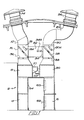
- cooling apparatus includes a cooling zone in the form of an open-ended tunnel which is indicated generally by reference numeral 2, and which is defined by an air supply chamber 4 and an air extraction chamber 6.
- a fan chamber 8 having a centrifugal fan 10, and air supply ducting 12 serving to connect the fan chamber 8 to atmosphere so that air from atmoshphere may be supplied to said fan chamber.
- the ducting 12 has a cowling 14, a removable filter screen 16, and an air supply control damper 18 which is movable by a piston-and-cylinder arrangement 18A.
- the air extraction chamber 6 has a fan chamber 20 having a centrifugal fan 22, and air extraction ducting 24 serving to connect the fan chamber 20 to exhaust.
- the ducting 24 has a cowling 26, a removable filter screen 28 and an air extraction control damper 30 movable by a piston-and-cylinder arrangement 30A.
- the piston-and cylinder arrangements 18A and 30A are controlled by automatic termperature sensing means.
- the ducting 12 and the ducting 24 are interconnected through the intermediary of recirculation ducting 32 having a movable damper 34 which is operable by a piston-and-cylinder arrangement 34A under the influence of automatic temperature sensing means.
- the damper 18 is positioned in the ducting 12 before the recirculation ducting 32 connection, that the damper 30 is positioned in the ducting 24 after the recirculation ducting 32, and that the damper 34 is positioned in proximity to the connection of the ductings 24 and 32.
- the ductings 12 and 24 are provided with manually operable dampers 36 and 38 respectively
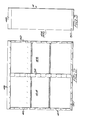
- the air supply chamber 4 comprises a rectangular box-like structure having end walls 40 and 42, rear panels 44 and 46 - which could conveniently be replaced by a single rear panel - and top and bottom walls 48 and 50.
- a centre column 52 extends between said top and bottom walls.
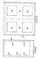
- Face plates - one is indicated by reference numeral 54 in Figure 4 - are secured to the front faces of the end walls 40 and 42, top and bottom walls 48 and 50, and centre column 52 so as to form the enclosed box-like structure, said front faces being suitably drilled or otherwise provided with means to secure said face plates to said faces.
- the face plates 54 have a plurality of regularly spaced holes 56 which are countersunk at their rear sides, i.e. the sides facing into the interior of the box-like structure. The form of each hole 56 will best be seen from Figure 5, where the countersunk portion 56A is clearly indicated.
- Said face plates will preferably be composed of polypropylene or other synthetic plastics material, although it will be appreciated that the plates may be composed of other material such as stainless steel.
- the face plates 54 may be replaced by a single face plate having the requisite number of regularly spaced holes to give the required rate of air flow into the cooling zone.
- the air extraction chamber 6 - referring now to Figure 6 - is again a rectangular box-like structure having front plates 58 and 60 having cut-outs 62, 64 and 66, 68 respectively over which are fitted grilles or louvres 69, Figure 1.
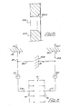
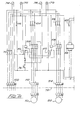
- circuit diagrams of the apparatus is shown in Figures 7A and 7B, and shows the marked terminal rail 102 within the panel and to which terminals the customer should connect the incoming electric supply. In addition, it shows to which terminals the panel components are wired.
- the internal wiring consists of power wiring for the two fans and control wiring for all other functions.
- the power wiring (3-phase and neutral) is taken from the terminal strip 102 through the isolator switch 70 to the 3 pole miniature circuit breakers 104 and 106 for the fans 10 and 22.
- the supply then goes to the contactors 108, overload relays 110 and to the terminal strip 112 and 114 for wiring out to the motors of the fans 10 and 22.
- the power for the 240 volt control circuitry is taken from one of the phases through the single pole miniature circuit breaker 116 and then to all the 240 volt control devices including indicator lamps 74, 75, 78 and 79, contactors 108, overload relays 110, transformer 118 and timer 120.
- the power for the 24 volt control circuitry is taken from the 240 volt control circuit through the 240/24 volt transformer 118 and single pole miniature circuit breaker 122 onto the electronic temperature controller 124, timer relay 126 and alarm circuit 128.
- the controller 124 is wired back to the terminals 130, 132, 134, 136, 138, 140 and 142 for connection to the temperature sensors 144 and 146 and damper actuators 148, 150, and 152.
- the temperature controller 124 has two wires run to the temperature set point adjustment dial 154.
- the alarm circuit is operated via start 156 and stop/reset 158 buttons which operate the relay 126 which activates the timer 120.
- the timer 120 switches, the power is transmitted to the audio alarm 160 and indicator 162.
- the audio alarm 160 is 24 volt D.C. and is fed through a rectifier 164, resistor 166 and capacitor 168.
- the apparatus is designed to supply coolant air to the cooling zone at a velocity of approximately 2.5 metres per second and over the product to be cooled.
- the isolator switch 70 on the control panel is moved to the "on" position when a green lamp 74 will be illuminated to indicate that the control circuit is operational.
- the termperature controls of the apparatus will now start to modulate as necessary.
- a push button 76 on the control panel 72 is then depressed so as to activate the air supply fan 10 and air extraction fan 22, when a green lamp 78 will be illuminated so as to indicate that the apparatus is now fully operational.
- the timer circuitry indicated generally by reference numeral 80 is operational.
- the control panel has a facility also for adjusting the set point for the temperature controls.
- the timer 80 can be adjusted between zero and thirty six minutes - dependent upon the product being cooled - and once set, it will reset to that time at the end of each cooling cycle.
- the push button 156 is depressed to commence the cycle, this state being indicated by a red neon on the timer.
- the amber lamp When the set time has elapsed, the amber lamp will glow and a continuous tone buzzer will sound, until the cycle is reset.
- the temperature control system consists of an electronic module which receives signals from the temperature sensors.
- the electronic module operates the motions of the dampers to achieve the pre-set temperature.
- the controls will control the temperature of the air as it leaves the product and will limit the air temperature onto the product (not shown) to be cooled.
- This method of control two advantages are gained. Firstly, when the product to be cooled enters the apparatus, the controls will sense that full cooling is required. In winter, this could mean a coolant air temperature of 30 0 F (-loC) which would be harmful to the product. The low limit control will prevent the supply air temperature falling below the pre-set temperature.
- the control sensor at the extraction side of the cooling zone, the air temperature will start to rise as the product cools (because less cooling is required) and will help to prevent over-cooling or drying of the product.
- the low limit temperature set point it set on the controller itself by adjusting an appropriate dial. This temperature will preferably be pre-set (usually on commissioning of the apparatus) and should not require adjustment unless it is felt that the temperature is too low or too high.
- the set point for the control temperature can be adjusted on the timer panel, the controls only being adjustable between outside (air from atmosphere) temperature and air recirculation temperature.
- the control temperature is adjustable to suit the type of product to be cooled.
- a small indicator lamp on the controller indicates its output as follows:
- a temperature detector positioned in the air extraction chamber 6 senses the temperature of the air passing from the product being cooled into the extraction chamber 6. If the air temperature starts to fall below the preset temperature which is set by the operator on the control panel, then the damper 18 in the air supply ducting 12 is modulated towards the closed position, the damper 30 in the extraction ducting 24 is modulated towards the closed position, and the damper 34 in the recirculation ducting 32 is modulated towards the open position.
- a temperature detector positioned in the air supply chamber 4 senses the temperature of the air passing through the holes 56 in the face plates 54 into the cooling zone (tunnel) 2, and if this temperature is below that which has been preset as a low limit, then damper 18 in the air supply ducting 12 is modulated towards the closed position, the damper 30 in the extraction ducting 24 is modulated towards the closed position, and the damper 34 in the recirculation ducting 32 is modulated towards the open position.
- Controls - panel isolator should be switched on.
- the temperature set point knob is turned to its maximum position - the damper 34 should fully open, and the dampers 18 and 30 should fully close. If the knob is then turned to the minimum position, all the dampers should start to move towards their opposite positions, it being noted that the dampers will not move fully to their opposite positions because the low temperature limit control will override this control if the air in the air supply side of the apparatus drops below the pre-set temperature.
- Fans - panel isolator should be switched on.
- the push button 76 on the main panel is pressed, and the fans will make a noise as they start and the indicator lamp will illuminate.
- the face plates 54 can be felt, and to ensure that air is being extracted a sheet of paper (or similar) can be held against the grilles of the extraction chamber 6. With the system running, all the circuit breakers in the panel should be in the "on" position.
- coolant air supplied by the fan 10 passes from the ducting 12 into the air supply chamber 4 and thence through the holes 56 in the face plates 54 thereof and over the products (not shown) to be cooled located in the cooling zone (tunnel) 2.
- the fan 22 of the extraction ducting 24 then pulls the air through the grilles of the extraction chamber 6 into said chamber 6, whereafter the air is passed to exhaust or back into the air supply ducting 12 - via the recirculation ducting 32 - this being determined (or the proportions of air to exhaust and air to recirculation) by the modulating positions of the dampers 18, 30 and 34.
- the products to be cooled will preferably be located on trollies (not shown) which are fed into one open end of the tunnel 2 which will preferably be of E length substantially equally to two trolley lengths.
- the trollies carrying the cooled products can exit from the other open end of the tunnel.
- guide rails may be provided in the tunnel along which the trollies may run, and means may be provided for feeding the trollies into and out of the tunnel.
- the apparatus With apparatus according to the invention, the usual bakehouse bottleneck caused by having to wait for baked products to cool is eliminated, since the cooling time is reduced to substantially the same as the time taken for baking.
- the apparatus becuase of its control system gives repeatable and constant cooling for each product. Cooling takes place without undue drying of the product and due to the recirculation of humidified air, over-cooling of the product is prevented. Of perhaps more importance, because the recirculated air has already passed over the product and absorbed moisture from the product, the recirculated air cannot continue to gather moisture and cause over-drying of the products. Thus over-cooling and over-drying of the products are not possible.
- Handling of the product is reduced, floor space is saved (due to the out of the way positioning of the fans etc), and the number of trollies, trays, and baking tins in use are all reduced, as is the labour force required.
- the cooling is controlled, the trollies, trays and baking tins finish at a constant temperature and therefore their constant temperature gives consistency to the next batch of production.
- the baked products suffer less of a weight loss than would be the case with any other cooling process or with natural cooling.
- the scaling weight of the dough piece to be baked can be reduced, and yet the finished product can attain the required finished weight.
- apparatus according to the invention may have uses other than in the baking industry.
- the cooling zone in its peferred form, is shown and described as a tunnel which is open at both ends, the tunnel may have only one end open, so that instead of the trolleys carrying the products to be cooled entering the tunnel through one end and exitting through the other end, the trolleys would enter and leave by the same opening.
- the extraction side of the apparatus may be constituted by a wall or other partition against which the cabinet abuts, cut-outs and grilles being provided in the wall or partition to provide for extraction of the air from the cooling zone.
Landscapes
- Life Sciences & Earth Sciences (AREA)
- Engineering & Computer Science (AREA)
- Food Science & Technology (AREA)
- Bakery Products And Manufacturing Methods Therefor (AREA)
- Manufacturing And Processing Devices For Dough (AREA)
Applications Claiming Priority (2)
| Application Number | Priority Date | Filing Date | Title |
|---|---|---|---|
| GB8318604 | 1983-07-08 | ||
| GB838318604A GB8318604D0 (en) | 1983-07-08 | 1983-07-08 | Cooling apparatus |
Publications (2)
| Publication Number | Publication Date |
|---|---|
| EP0131448A2 true EP0131448A2 (fr) | 1985-01-16 |
| EP0131448A3 EP0131448A3 (fr) | 1986-07-30 |
Family
ID=10545471
Family Applications (1)
| Application Number | Title | Priority Date | Filing Date |
|---|---|---|---|
| EP84304630A Withdrawn EP0131448A3 (fr) | 1983-07-08 | 1984-07-06 | Dispositif de refroidissement |
Country Status (6)
| Country | Link |
|---|---|
| US (1) | US4562701A (fr) |
| EP (1) | EP0131448A3 (fr) |
| JP (1) | JPS6091932A (fr) |
| AU (1) | AU3033784A (fr) |
| GB (1) | GB8318604D0 (fr) |
| ZA (1) | ZA845211B (fr) |
Cited By (4)
| Publication number | Priority date | Publication date | Assignee | Title |
|---|---|---|---|---|
| US5109761A (en) * | 1988-05-23 | 1992-05-05 | Gray John B | Rapid bread cooling apparatus |
| DE4320482A1 (de) * | 1993-06-21 | 1995-01-12 | Stulz Gmbh | Verfahren zum Abkühlen und nachfolgenden Konfektionieren von Lebensmitteln |
| WO1998019547A1 (fr) * | 1996-11-06 | 1998-05-14 | Franz Haas Waffelmaschinen-Industrie Aktiengesellschaft | Procede de traitement de produits a base d'amidon |
| US7188465B2 (en) | 2003-11-10 | 2007-03-13 | General Electric Company | Method and apparatus for actuating fuel trim valves in a gas turbine |
Families Citing this family (7)
| Publication number | Priority date | Publication date | Assignee | Title |
|---|---|---|---|---|
| US5902618A (en) * | 1997-03-04 | 1999-05-11 | Haasis, Jr.; Hans | Efficient food chilling method |
| US5968578A (en) * | 1997-12-08 | 1999-10-19 | Knisely; Charles W. | Baking system and method using oscillating baffles for heat transfer enhancement |
| US6066043A (en) * | 1997-12-08 | 2000-05-23 | Knisely; Charles W. | Oscillating baffle for airflow redirection and heat transfer enhancement |
| JPWO2005107480A1 (ja) * | 2004-05-07 | 2008-07-31 | 株式会社前川製作所 | 焼成食品の冷凍保存方法及び装置 |
| US20070084321A1 (en) * | 2005-10-13 | 2007-04-19 | Michel Ciambella | Method and apparatus for rapid cooling of baked goods |
| EP2878803B1 (fr) | 2012-07-11 | 2018-05-16 | Kawasaki Jukogyo Kabushiki Kaisha | Motocyclette avec conduit d'admission d'air |
| CN103557572A (zh) * | 2013-11-18 | 2014-02-05 | 中国建筑第八工程局有限公司 | 外墙风管结构及其施工方法 |
Family Cites Families (17)
| Publication number | Priority date | Publication date | Assignee | Title |
|---|---|---|---|---|
| GB364560A (en) * | 1930-08-28 | 1931-12-28 | B F Sturtevant Co | Improvements in or relating to drying kilns |
| GB403398A (en) * | 1932-04-12 | 1933-12-12 | John Henry Morton | Improvements in and connected with apparatus for drying vegetables and other substances or materials |
| GB414037A (en) * | 1933-01-24 | 1934-07-24 | Evan George Wilson | Improvements in or relating to chambers or structures for the drying or conditioningof hides, skins, pelts, and other similar substances |
| GB426484A (en) * | 1933-09-30 | 1935-04-01 | British United Shoe Machinery | Improvements in or relating to heating apparatus suitable for use in the manufactureof boots or shoes |
| GB478541A (en) * | 1936-12-08 | 1938-01-20 | W E Long Company | Improvements in apparatus for cooling bakery products |
| GB494431A (en) * | 1937-05-20 | 1938-10-26 | Joseph Chandley Macarty | An improved unitary air dryer |
| US2257487A (en) * | 1937-08-19 | 1941-09-30 | Tenney Dwight | Bread cooler |
| GB489749A (en) * | 1937-11-25 | 1938-08-03 | Proctor & Schwartz Inc | An improved method of and apparatus for drying leather |
| GB618227A (en) * | 1945-03-20 | 1949-02-18 | John Richard Seville | Bread cooling and storage plant |
| GB724057A (en) * | 1952-11-28 | 1955-02-16 | Courtaulds Ltd | Improvements in and relating to drying tunnels |
| GB762677A (en) * | 1953-11-12 | 1956-12-05 | Humidity Control Ltd | Improvements in and relating to the cooling of bread |
| US2984082A (en) * | 1956-12-10 | 1961-05-16 | Robert C Coblentz | Air conditioning system |
| GB970504A (en) * | 1962-06-13 | 1964-09-23 | T & T Vicars Ltd | Improvements in or relating to circulation systems for gaseous media |
| SE319128B (fr) * | 1968-09-24 | 1969-12-22 | Svenska Flaektfabriken Ab | |
| DE2647438C2 (de) * | 1976-10-21 | 1986-11-13 | Hauni-Werke Körber & Co KG, 2050 Hamburg | Verfahren und Vorrichtung zum Abtrocknen von Burley- oder von Grünblatt-Tabak |
| DE2724037A1 (de) * | 1977-05-27 | 1978-12-07 | Hauni Werke Koerber & Co Kg | Vorrichtung zum trocknen eines kontinuierlich gefoerderten tabakstromes |
| DE3109458A1 (de) * | 1981-03-09 | 1982-09-23 | Schering Ag, 1000 Berlin Und 4619 Bergkamen | Hordentrockenschrank |
-
1983
- 1983-07-08 GB GB838318604A patent/GB8318604D0/en active Pending
-
1984
- 1984-07-06 AU AU30337/84A patent/AU3033784A/en not_active Abandoned
- 1984-07-06 US US06/628,696 patent/US4562701A/en not_active Expired - Fee Related
- 1984-07-06 ZA ZA845211A patent/ZA845211B/xx unknown
- 1984-07-06 EP EP84304630A patent/EP0131448A3/fr not_active Withdrawn
- 1984-07-09 JP JP59143177A patent/JPS6091932A/ja active Pending
Cited By (6)
| Publication number | Priority date | Publication date | Assignee | Title |
|---|---|---|---|---|
| US5109761A (en) * | 1988-05-23 | 1992-05-05 | Gray John B | Rapid bread cooling apparatus |
| DE4320482A1 (de) * | 1993-06-21 | 1995-01-12 | Stulz Gmbh | Verfahren zum Abkühlen und nachfolgenden Konfektionieren von Lebensmitteln |
| WO1998019547A1 (fr) * | 1996-11-06 | 1998-05-14 | Franz Haas Waffelmaschinen-Industrie Aktiengesellschaft | Procede de traitement de produits a base d'amidon |
| US6082250A (en) * | 1996-11-06 | 2000-07-04 | Franz Haas Waffelmaschinen-Industrie Aktiengesellschaft | Device for treating starch-based products |
| US7188465B2 (en) | 2003-11-10 | 2007-03-13 | General Electric Company | Method and apparatus for actuating fuel trim valves in a gas turbine |
| US7260937B2 (en) | 2003-11-10 | 2007-08-28 | General Electric Company | Method and apparatus for actuating fuel trim valves in a gas turbine |
Also Published As
| Publication number | Publication date |
|---|---|
| US4562701A (en) | 1986-01-07 |
| AU3033784A (en) | 1985-01-10 |
| JPS6091932A (ja) | 1985-05-23 |
| ZA845211B (en) | 1985-03-27 |
| EP0131448A3 (fr) | 1986-07-30 |
| GB8318604D0 (en) | 1983-08-10 |
Similar Documents
| Publication | Publication Date | Title |
|---|---|---|
| US4562701A (en) | Cooling apparatus | |
| US4389562A (en) | Conveyor oven | |
| US3861378A (en) | Reversible air flow oven | |
| US4972824A (en) | Commercial hot air impingement cooking apparatus | |
| US4245613A (en) | Tunnel oven | |
| US5463940A (en) | Proofing oven | |
| US6252201B1 (en) | Small fast acting conveyor toaster oven | |
| EP0934699A2 (fr) | Petit four/toasteur à convoyeur | |
| US2988351A (en) | Mold drying and cooling oven | |
| CA2137995C (fr) | Four a circulation d'air chaud | |
| JPH02249443A (ja) | オーブン装置、オーブン、グリドル、グリル装置及びピザ調理方法 | |
| US4004129A (en) | Food processing oven | |
| EP0127355A3 (fr) | Four à transporteur | |
| US7205507B2 (en) | Food cooking and heating apparatus | |
| US4987688A (en) | Fruit-processing oven, particularly for converting raw plums into prunes by desiccation | |
| US2257487A (en) | Bread cooler | |
| US5050578A (en) | Commercial hot air impingement cooking apparatus | |
| US5937845A (en) | Alternating horizontal air flow oven | |
| EP0381001A2 (fr) | Système de séchage pour pâtes alimentaires ou produits similaires | |
| US2548524A (en) | Electrical cooking apparatus | |
| US7806045B2 (en) | Scheduling and tracking system and method for bakery products | |
| CA2607582C (fr) | Systeme et procede de programmation et de suivi destines a la production de produits de boulangerie | |
| RU2146449C1 (ru) | Хлебопекарная печь | |
| CN113670058A (zh) | 一种红外线烘烤装置 | |
| GB2072479A (en) | Automatic final baking oven for pre-baked dough-based products |
Legal Events
| Date | Code | Title | Description |
|---|---|---|---|
| PUAI | Public reference made under article 153(3) epc to a published international application that has entered the european phase |
Free format text: ORIGINAL CODE: 0009012 |
|
| AK | Designated contracting states |
Designated state(s): AT BE CH DE FR GB IT LI LU NL SE |
|
| PUAL | Search report despatched |
Free format text: ORIGINAL CODE: 0009013 |
|
| AK | Designated contracting states |
Kind code of ref document: A3 Designated state(s): AT BE CH DE FR GB IT LI LU NL SE |
|
| 17P | Request for examination filed |
Effective date: 19861224 |
|
| STAA | Information on the status of an ep patent application or granted ep patent |
Free format text: STATUS: THE APPLICATION IS DEEMED TO BE WITHDRAWN |
|
| 18D | Application deemed to be withdrawn |
Effective date: 19890202 |
|
| RIN1 | Information on inventor provided before grant (corrected) |
Inventor name: NEWSOME, GEORGE Inventor name: NEWTON, ERIC |