EP0131618B1 - Vent line system - Google Patents
Vent line system Download PDFInfo
- Publication number
- EP0131618B1 EP0131618B1 EP84900664A EP84900664A EP0131618B1 EP 0131618 B1 EP0131618 B1 EP 0131618B1 EP 84900664 A EP84900664 A EP 84900664A EP 84900664 A EP84900664 A EP 84900664A EP 0131618 B1 EP0131618 B1 EP 0131618B1
- Authority
- EP
- European Patent Office
- Prior art keywords
- vent line
- connecting element
- deflect
- flow
- line
- Prior art date
- Legal status (The legal status is an assumption and is not a legal conclusion. Google has not performed a legal analysis and makes no representation as to the accuracy of the status listed.)
- Expired
Links
- 238000005553 drilling Methods 0.000 claims abstract description 34
- 239000012530 fluid Substances 0.000 claims abstract description 16
- 239000000463 material Substances 0.000 claims description 4
- 230000003628 erosive effect Effects 0.000 claims description 3
- 238000012856 packing Methods 0.000 description 6
- 229910000831 Steel Inorganic materials 0.000 description 3
- 238000005520 cutting process Methods 0.000 description 3
- 239000010959 steel Substances 0.000 description 3
- 238000004891 communication Methods 0.000 description 2
- 230000004075 alteration Effects 0.000 description 1
- 230000015572 biosynthetic process Effects 0.000 description 1
- 238000005524 ceramic coating Methods 0.000 description 1
- 230000008859 change Effects 0.000 description 1
- 239000011248 coating agent Substances 0.000 description 1
- 238000000576 coating method Methods 0.000 description 1
- 239000004020 conductor Substances 0.000 description 1
- 230000008878 coupling Effects 0.000 description 1
- 238000010168 coupling process Methods 0.000 description 1
- 238000005859 coupling reaction Methods 0.000 description 1
- 238000004519 manufacturing process Methods 0.000 description 1
- 238000012986 modification Methods 0.000 description 1
- 230000004048 modification Effects 0.000 description 1
- 230000001681 protective effect Effects 0.000 description 1
- 238000007789 sealing Methods 0.000 description 1
- 239000007787 solid Substances 0.000 description 1
- 239000013077 target material Substances 0.000 description 1
- 238000012360 testing method Methods 0.000 description 1
- WFKWXMTUELFFGS-UHFFFAOYSA-N tungsten Chemical compound [W] WFKWXMTUELFFGS-UHFFFAOYSA-N 0.000 description 1
- 229910052721 tungsten Inorganic materials 0.000 description 1
- 239000010937 tungsten Substances 0.000 description 1
- 238000013022 venting Methods 0.000 description 1
Images
Classifications
-
- F—MECHANICAL ENGINEERING; LIGHTING; HEATING; WEAPONS; BLASTING
- F16—ENGINEERING ELEMENTS AND UNITS; GENERAL MEASURES FOR PRODUCING AND MAINTAINING EFFECTIVE FUNCTIONING OF MACHINES OR INSTALLATIONS; THERMAL INSULATION IN GENERAL
- F16K—VALVES; TAPS; COCKS; ACTUATING-FLOATS; DEVICES FOR VENTING OR AERATING
- F16K11/00—Multiple-way valves, e.g. mixing valves; Pipe fittings incorporating such valves
- F16K11/02—Multiple-way valves, e.g. mixing valves; Pipe fittings incorporating such valves with all movable sealing faces moving as one unit
- F16K11/08—Multiple-way valves, e.g. mixing valves; Pipe fittings incorporating such valves with all movable sealing faces moving as one unit comprising only taps or cocks
- F16K11/085—Multiple-way valves, e.g. mixing valves; Pipe fittings incorporating such valves with all movable sealing faces moving as one unit comprising only taps or cocks with cylindrical plug
- F16K11/0853—Multiple-way valves, e.g. mixing valves; Pipe fittings incorporating such valves with all movable sealing faces moving as one unit comprising only taps or cocks with cylindrical plug having all the connecting conduits situated in a single plane perpendicular to the axis of the plug
-
- E—FIXED CONSTRUCTIONS
- E21—EARTH OR ROCK DRILLING; MINING
- E21B—EARTH OR ROCK DRILLING; OBTAINING OIL, GAS, WATER, SOLUBLE OR MELTABLE MATERIALS OR A SLURRY OF MINERALS FROM WELLS
- E21B21/00—Methods or apparatus for flushing boreholes, e.g. by use of exhaust air from motor
- E21B21/08—Controlling or monitoring pressure or flow of drilling fluid, e.g. automatic filling of boreholes, automatic control of bottom pressure
-
- E—FIXED CONSTRUCTIONS
- E21—EARTH OR ROCK DRILLING; MINING
- E21B—EARTH OR ROCK DRILLING; OBTAINING OIL, GAS, WATER, SOLUBLE OR MELTABLE MATERIALS OR A SLURRY OF MINERALS FROM WELLS
- E21B21/00—Methods or apparatus for flushing boreholes, e.g. by use of exhaust air from motor
- E21B21/001—Methods or apparatus for flushing boreholes, e.g. by use of exhaust air from motor specially adapted for underwater drilling
-
- E—FIXED CONSTRUCTIONS
- E21—EARTH OR ROCK DRILLING; MINING
- E21B—EARTH OR ROCK DRILLING; OBTAINING OIL, GAS, WATER, SOLUBLE OR MELTABLE MATERIALS OR A SLURRY OF MINERALS FROM WELLS
- E21B21/00—Methods or apparatus for flushing boreholes, e.g. by use of exhaust air from motor
- E21B21/10—Valve arrangements in drilling-fluid circulation systems
- E21B21/106—Valve arrangements outside the borehole, e.g. kelly valves
Definitions
- the invention disclosed herein relates to a diverter apparatus and system for redirecting the flow of drilling fluid or mud and cuttings that would otherwise be blown upward to the rig floor during a "kick" encountered during initial hole drilling.
- the apparatus and system according to the invention may be used beneath the drilling floor of any land or marine drilling rig, but in particular the invention finds application with floating, drilling equipment.
- the invention relates to a vent line system for connecting to a diverter in which the system has a blast deflecting means to deflect the mud and cuttings flowing in the vent line overboard assuring that no means are provided to prevent such flow.
- Flow diverters are typically provided below the rig floor and between the riser and the rotary table of the drilling rig for the purpose of safely venting unbalanced well bore pressure which may produce an upward flow of well flow fluid in the riser having sufficient impetus to issue from the top of the riser, thereby contributing a hazard to personnel and equipment.
- a "kick" results when the formation fluid pressure exceeds the head in the riser and borehole and is sometimes en countered in conductor hole drilling, making a flow diverter essential before blowout preventers are connected to the drilling system.
- a flow diverter is considered necessary for safe operation on a floating offshore drilling rig where blowout preventers are placed on the sea floor only after the casing has been set to a considerable depth below the sea floor.
- vent line system Flow diverter systems which have been provided in the past have faced significant safety problems because the available equipment has required that valves external to the diverter be placed in the vent line system. Such valves have been necessary because the vent line was in general open to the annulus of the drilling conduit below the diverter element adapted for closing the vertical flow path of the bore. The vent line valve was opened simultaneously with or prior to the closing of the diverter element.
- a "T" joint has been provided to direct flow in the vent line to one of two discharge lines, one leading to the port side of the vessel, the other to the starboard. Valves in each of the discharge lines enabled rig personnel to close one of the discharge lines so that vent line flow could be discharged to the leeward side of the vessel.
- US-A- 3,917,008 discloses a diverting system wherein a vent line is open to the drilling conduit below the blowout preventer and is connected to an external diverter valve that is normally biased to close a diverter line for directing drilling fluid away from the drilling rig.
- This system is essentially subject to the same difficulties as the other prior art systems noted above since it relies on an external diverter valve which must operate without fail or otherwise the vent line and diverter line cannot release drilling fluid in the event of a "kick".
- vent line system which, when used in combination with a novel flow diverter which requires no external vent line valves, is failsafe; that is, when a kick occurs during shallow hole drilling of a well before a blowout preventer has been provided, that kick cannot be accidently confined by the vent line system to build pressure and explode even if controls are misconnected or malfunctioning.
- the present invention provides a diverting system for directing drilling fluid away from a drilling rig in the event of a kick comprising a vent line adapted for connection to a flow diverter and a deflect line connected at one end to said vent line and having its other end open to the atmosphere, characterized in that the vent line is uninterruptible and has one end connected to said flow diverter, said deflect line being one of two uninterruptible deflect lines extending in different directions away from said drilling rig, said system including deflecting means connected to one end of each of said two deflect lines and to the other end of said vent line for directing fluid to at least one of said two deflect lines while assuring against simultaneous closure of said two deflect lines.
- the first includes a deflecting element which may be angularly rotated in the body of the deflecting unit to direct the flow to one or the other of the outlet ports.
- a deflecting element is adapted to move in a linear direction between two positions intermediate the inlet and outlet ports and accomplishes the same function as the first embodiment.
- a third embodiment of the deflecting unit is a rotary sleeve blast deflector/selector in which the axis of the sleeve is parallel to the inlet flow and a removable target is provided for impingement of abrasive well flow.
- vent line system of the invention requires but a single motion to operate, is simple and relatively inexpensive to manufacture.
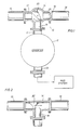
- FIG. 1 illustrates the vent line system shown generally at 10 in which a vent line 11 is connected to a flow diverter 12.
- diverter 12 is preferably connected below a drilling rig floor above a drilling conduit and is provided with means for connecting the vent line 11 for directing drilling rig mud and cuttings away from the rig floor on the occasion of a kick.
- Attached to the diverter also is a flow line means 13 which is connected to the drilling rig mud system.
- the blast deflecting unit 14 of the system 10 is a "T" shaped connecting element having an inlet port 15 and outlet ports 16 and 17. Outlet ports 16 and 17 are connected to deflect lines 18 and 19 for directing the flow from the diverter 11 in two directions. Typically one of the deflect lines is directed to the port side of the vessel, while the other deflect line is directed to the starboard side.
- a blast deflector element 20 disposed within the body of the deflecting unit 14 is adapted to be placed in two positions. As illustrated in Figure 1 the deflector element 20 is disposed in a cylindrical or alternatively a spherically shaped body and is adapted to be placed in one of two directions for deflecting the flow from inlet port 15 to one or the other of the deflecting lines 18 or 19.
- Figure 2 shows an alternative embodiment of the deflecting unit 14' in which a blast deflector element 20' is adapted to move linearly along the body 14' to opposite positions whereby flow from the inlet port 15 is deflected to deflect lines 18 or 19.
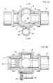
- FIGs 3A and 3B illustrate another alternative embodiment of the deflecting unit 14" in which the axis of he deflecting element, in this embodiment a rotary sleeve 30, is provided parallel to the inlet port 15.
- a target 20 preferably one that may be easily replaced by opening target housing 31, provides a sacrificial erosive surface for impingement of abrasive solids in the well flow entering inlet port 15.
- the rotary sleeve 30 is in position to direct flow from inlet port 15 to outlet port 18. After rotary sleeve is rotated counter-clockwise by ninety degrees, inlet port 15 is opened to outlet port 19.
- An actuator 35 is provided to rotate sleeve 30.
- the rotary actuator may be a motor 35 and gear 35' arrangement coupled to sleeve 30, but may be any motive and coupling means commonly employed in oilfield applications for actuating valve elements.
- Seals 36,37 are provided in body 14" for sealing against rotary sleeve 30.
- a seal 40 is provided to seal target material 20" against the body 14".
- a slot 38 in sleeve 30 and a stop 39 insures that sleeve 30 may travel only between the position shown in Figures 3A and one which is ninety degrees counterclockwise from that illustrated.
- the deflector element 20, 20' or 20" is constructed from a material suited to be highly resistant to erosion from abrasive fluid flow.
- a material suited to be highly resistant to erosion from abrasive fluid flow.
- Such material may be carbide coated steel, steel with a tungsten coating, steel having a ceramic coating on the blast surface, or any suitable material.
- the deflector element and vent line system provide a simple device which requires but a single motion to operate between one of two states, yet the vent line system is always open to the diverter thereby assuring that the vent line system itself is prohibited from being closed and thereby insuring that pressurized gas from the drilling conduit to which the diverter 12 is connected is diverted away from the drilling vessel. Even if the deflecting element 20 is unintentionally left in a position causing the vent line fluid and mud to be directed to the windward side of the vessel, all that is required to direct the flow to the leeward side is to change the position of the deflecting unit 20 or 20' or 20".
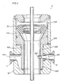
- the diverter 12 is preferably of the type requiring no external valves in the vent line 15. Such a diverter is presented by way of example in Figure 4.
- Figure 4 illustrates an embodiment of the flow diverter 12 in which a piston 500 is provided not only for closing the annular packing element 52 about an object in the bore of the diverter, but also for closing a flow line 13 and opening a vent line 11 during an emergency.
- the piston 500 has an upper conical bowl portion 502 adapted for engagement with a packing element 52 and forcing it radially inward as the piston 500 moves axially upward.
- a hole 510 in the piston wall is normally in alignment with a hole 512 in the body 50 of the diverter 12.
- the second hole 513 in the body wall, provided in alignment with the vent line 11, is covered by the piston 500 wall when the diverter is in its normal state.
- piston 500 When a source of high pressure hydraulic fluid is provided beneath the piston 500 via conduit 520, piston 500 is forced upward thereby opening vent line 11 via hole 513 providing fluid communication with the bore of the diverter 12. As piston 500 moves up, hole 512 in the body wall becomes covered by the lower part 525 of piston 500, and ultimately, hole 512 becomes completely covered by the lower part 525 of the piston.
- Means are provided for insuring that the packing element 52 does not close about a pipe or other object in the bore hole before hole 512 is covered and hole 513 is opened by providing a space 530 above the packing element through which the packing element is free to move axially upward without being forced radially inward as the upper conical portion 502 of the piston 500 moves up.
- a means is provided by which the vent line 11 is opened and the flow line 13 is closed from fluid communication with the bore of the flow diverter 12 before the annular packing element 52 is enabled to fully close about a pipe or other object in the bore hole or to completely close the vertical flow path of the diverter 12 in the absence of an object in the bore.
- vent line system for use with a flow diverter in which no valves external to the diverter are provided, assuring that inadvertent errors in operation or inopera- tiveness of valves external to the diverter do not create the opportunity for closing flow exits from the diverter after the annulus is closed.
Landscapes
- Engineering & Computer Science (AREA)
- Geology (AREA)
- Life Sciences & Earth Sciences (AREA)
- Mining & Mineral Resources (AREA)
- Mechanical Engineering (AREA)
- Physics & Mathematics (AREA)
- Environmental & Geological Engineering (AREA)
- Fluid Mechanics (AREA)
- General Life Sciences & Earth Sciences (AREA)
- Geochemistry & Mineralogy (AREA)
- General Engineering & Computer Science (AREA)
- Earth Drilling (AREA)
- Multiple-Way Valves (AREA)
Priority Applications (1)
| Application Number | Priority Date | Filing Date | Title |
|---|---|---|---|
| AT84900664T ATE35844T1 (de) | 1983-01-17 | 1984-01-09 | Auslassvorrichtung. |
Applications Claiming Priority (2)
| Application Number | Priority Date | Filing Date | Title |
|---|---|---|---|
| US45820683A | 1983-01-17 | 1983-01-17 | |
| US458206 | 1983-01-17 |
Publications (2)
| Publication Number | Publication Date |
|---|---|
| EP0131618A1 EP0131618A1 (en) | 1985-01-23 |
| EP0131618B1 true EP0131618B1 (en) | 1988-07-20 |
Family
ID=23819800
Family Applications (1)
| Application Number | Title | Priority Date | Filing Date |
|---|---|---|---|
| EP84900664A Expired EP0131618B1 (en) | 1983-01-17 | 1984-01-09 | Vent line system |
Country Status (5)
| Country | Link |
|---|---|
| EP (1) | EP0131618B1 (da) |
| JP (1) | JPS60500455A (da) |
| CA (1) | CA1221603A (da) |
| DE (1) | DE3472819D1 (da) |
| WO (1) | WO1984002949A1 (da) |
Families Citing this family (2)
| Publication number | Priority date | Publication date | Assignee | Title |
|---|---|---|---|---|
| US4626135A (en) * | 1984-10-22 | 1986-12-02 | Hydril Company | Marine riser well control method and apparatus |
| US4646844A (en) * | 1984-12-24 | 1987-03-03 | Hydril Company | Diverter/bop system and method for a bottom supported offshore drilling rig |
Citations (6)
| Publication number | Priority date | Publication date | Assignee | Title |
|---|---|---|---|---|
| US2021104A (en) * | 1933-08-26 | 1935-11-12 | Leland P Kinnear | Blow-out preventer |
| US3805833A (en) * | 1971-10-20 | 1974-04-23 | G Teed | Back-suction diverter valve |
| US3856037A (en) * | 1973-01-22 | 1974-12-24 | Fmc Corp | Valve sequence interlock system |
| US3917008A (en) * | 1974-10-29 | 1975-11-04 | Cities Service Co | Apparatus and process for preventing blow-outs |
| US4046191A (en) * | 1975-07-07 | 1977-09-06 | Exxon Production Research Company | Subsea hydraulic choke |
| US4063602A (en) * | 1975-08-13 | 1977-12-20 | Exxon Production Research Company | Drilling fluid diverter system |
-
1984
- 1984-01-09 WO PCT/US1984/000013 patent/WO1984002949A1/en not_active Ceased
- 1984-01-09 EP EP84900664A patent/EP0131618B1/en not_active Expired
- 1984-01-09 JP JP59500677A patent/JPS60500455A/ja active Granted
- 1984-01-09 DE DE8484900664T patent/DE3472819D1/de not_active Expired
- 1984-01-13 CA CA000445290A patent/CA1221603A/en not_active Expired
Patent Citations (6)
| Publication number | Priority date | Publication date | Assignee | Title |
|---|---|---|---|---|
| US2021104A (en) * | 1933-08-26 | 1935-11-12 | Leland P Kinnear | Blow-out preventer |
| US3805833A (en) * | 1971-10-20 | 1974-04-23 | G Teed | Back-suction diverter valve |
| US3856037A (en) * | 1973-01-22 | 1974-12-24 | Fmc Corp | Valve sequence interlock system |
| US3917008A (en) * | 1974-10-29 | 1975-11-04 | Cities Service Co | Apparatus and process for preventing blow-outs |
| US4046191A (en) * | 1975-07-07 | 1977-09-06 | Exxon Production Research Company | Subsea hydraulic choke |
| US4063602A (en) * | 1975-08-13 | 1977-12-20 | Exxon Production Research Company | Drilling fluid diverter system |
Also Published As
| Publication number | Publication date |
|---|---|
| WO1984002949A1 (en) | 1984-08-02 |
| DE3472819D1 (de) | 1988-08-25 |
| CA1221603A (en) | 1987-05-12 |
| JPH0215718B2 (da) | 1990-04-12 |
| EP0131618A1 (en) | 1985-01-23 |
| JPS60500455A (ja) | 1985-04-04 |
Similar Documents
| Publication | Publication Date | Title |
|---|---|---|
| US4566494A (en) | Vent line system | |
| US4444401A (en) | Flow diverter seal with respective oblong and circular openings | |
| US4502534A (en) | Flow diverter | |
| US4456063A (en) | Flow diverter | |
| US4456062A (en) | Flow diverter | |
| US4444250A (en) | Flow diverter | |
| US4597447A (en) | Diverter/bop system and method for a bottom supported offshore drilling rig | |
| US4546828A (en) | Diverter system and blowout preventer | |
| US4832126A (en) | Diverter system and blowout preventer | |
| US4828024A (en) | Diverter system and blowout preventer | |
| US4646844A (en) | Diverter/bop system and method for a bottom supported offshore drilling rig | |
| US4709900A (en) | Choke valve especially used in oil and gas wells | |
| US4046191A (en) | Subsea hydraulic choke | |
| US4340088A (en) | Pressure balanced safety valve for wells and flow lines | |
| US4197879A (en) | Lubricator valve apparatus | |
| US4220176A (en) | Methods and apparatus for controlling fluid flow | |
| GB2287263A (en) | Tubing hangers | |
| US4461316A (en) | Drilling choke | |
| US6986499B2 (en) | Valve, actuator and control system therefor | |
| NO180055B (no) | Utblåsningssikring for avstenging av et ringrom mellom en borestreng og en brönnvegg ved boring etter olje eller gass | |
| WO2007085046A1 (en) | Bore selector | |
| EP0131618B1 (en) | Vent line system | |
| US20030145995A1 (en) | Riser connector | |
| EP0128206B1 (en) | Flow diverter | |
| NO165651B (no) | Avledningssystem. |
Legal Events
| Date | Code | Title | Description |
|---|---|---|---|
| PUAI | Public reference made under article 153(3) epc to a published international application that has entered the european phase |
Free format text: ORIGINAL CODE: 0009012 |
|
| AK | Designated contracting states |
Designated state(s): AT BE CH DE FR GB LI LU NL SE |
|
| 17P | Request for examination filed |
Effective date: 19841203 |
|
| GRAA | (expected) grant |
Free format text: ORIGINAL CODE: 0009210 |
|
| AK | Designated contracting states |
Kind code of ref document: B1 Designated state(s): AT BE CH DE FR GB LI LU NL SE |
|
| PG25 | Lapsed in a contracting state [announced via postgrant information from national office to epo] |
Ref country code: NL Effective date: 19880720 Ref country code: BE Effective date: 19880720 Ref country code: LI Effective date: 19880720 Ref country code: CH Effective date: 19880720 Ref country code: SE Effective date: 19880720 Ref country code: AT Effective date: 19880720 |
|
| REF | Corresponds to: |
Ref document number: 35844 Country of ref document: AT Date of ref document: 19880815 Kind code of ref document: T |
|
| REF | Corresponds to: |
Ref document number: 3472819 Country of ref document: DE Date of ref document: 19880825 |
|
| ET | Fr: translation filed | ||
| REG | Reference to a national code |
Ref country code: CH Ref legal event code: PL |
|
| NLV1 | Nl: lapsed or annulled due to failure to fulfill the requirements of art. 29p and 29m of the patents act | ||
| PG25 | Lapsed in a contracting state [announced via postgrant information from national office to epo] |
Ref country code: LU Free format text: LAPSE BECAUSE OF NON-PAYMENT OF DUE FEES Effective date: 19890131 |
|
| PLBE | No opposition filed within time limit |
Free format text: ORIGINAL CODE: 0009261 |
|
| STAA | Information on the status of an ep patent application or granted ep patent |
Free format text: STATUS: NO OPPOSITION FILED WITHIN TIME LIMIT |
|
| 26N | No opposition filed | ||
| REG | Reference to a national code |
Ref country code: GB Ref legal event code: IF02 |
|
| PGFP | Annual fee paid to national office [announced via postgrant information from national office to epo] |
Ref country code: FR Payment date: 20020117 Year of fee payment: 19 |
|
| PGFP | Annual fee paid to national office [announced via postgrant information from national office to epo] |
Ref country code: DE Payment date: 20020118 Year of fee payment: 19 |
|
| PGFP | Annual fee paid to national office [announced via postgrant information from national office to epo] |
Ref country code: GB Payment date: 20020121 Year of fee payment: 19 |
|
| PG25 | Lapsed in a contracting state [announced via postgrant information from national office to epo] |
Ref country code: GB Free format text: LAPSE BECAUSE OF NON-PAYMENT OF DUE FEES Effective date: 20030109 |
|
| PG25 | Lapsed in a contracting state [announced via postgrant information from national office to epo] |
Ref country code: DE Free format text: LAPSE BECAUSE OF NON-PAYMENT OF DUE FEES Effective date: 20030801 |
|
| GBPC | Gb: european patent ceased through non-payment of renewal fee |
Effective date: 20030109 |
|
| PG25 | Lapsed in a contracting state [announced via postgrant information from national office to epo] |
Ref country code: FR Free format text: LAPSE BECAUSE OF NON-PAYMENT OF DUE FEES Effective date: 20030930 |
|
| REG | Reference to a national code |
Ref country code: FR Ref legal event code: ST |