EP0131633B1 - Frequenzumwandler - Google Patents
Frequenzumwandler Download PDFInfo
- Publication number
- EP0131633B1 EP0131633B1 EP84900532A EP84900532A EP0131633B1 EP 0131633 B1 EP0131633 B1 EP 0131633B1 EP 84900532 A EP84900532 A EP 84900532A EP 84900532 A EP84900532 A EP 84900532A EP 0131633 B1 EP0131633 B1 EP 0131633B1
- Authority
- EP
- European Patent Office
- Prior art keywords
- unit
- circular
- waveguide
- rectangular waveguide
- converter
- Prior art date
- Legal status (The legal status is an assumption and is not a legal conclusion. Google has not performed a legal analysis and makes no representation as to the accuracy of the status listed.)
- Expired
Links
- 230000010355 oscillation Effects 0.000 claims abstract description 17
- 230000005540 biological transmission Effects 0.000 claims description 11
- 238000000034 method Methods 0.000 claims description 3
- 238000006243 chemical reaction Methods 0.000 description 9
- 230000001629 suppression Effects 0.000 description 8
- 230000002265 prevention Effects 0.000 description 4
- 238000004891 communication Methods 0.000 description 2
- 230000003247 decreasing effect Effects 0.000 description 2
- 230000007547 defect Effects 0.000 description 2
- 230000006866 deterioration Effects 0.000 description 2
- 238000010586 diagram Methods 0.000 description 2
- 230000000694 effects Effects 0.000 description 2
- 238000012545 processing Methods 0.000 description 2
- 230000002411 adverse Effects 0.000 description 1
- 230000002238 attenuated effect Effects 0.000 description 1
- 238000010276 construction Methods 0.000 description 1
- 238000013461 design Methods 0.000 description 1
- 230000002542 deteriorative effect Effects 0.000 description 1
- 238000006073 displacement reaction Methods 0.000 description 1
- 230000005672 electromagnetic field Effects 0.000 description 1
- 238000003780 insertion Methods 0.000 description 1
- 230000037431 insertion Effects 0.000 description 1
- 230000001902 propagating effect Effects 0.000 description 1
- 238000011084 recovery Methods 0.000 description 1
- 239000000523 sample Substances 0.000 description 1
- 239000000758 substrate Substances 0.000 description 1
- 230000007704 transition Effects 0.000 description 1
Images





Classifications
-
- H—ELECTRICITY
- H03—ELECTRONIC CIRCUITRY
- H03D—DEMODULATION OR TRANSFERENCE OF MODULATION FROM ONE CARRIER TO ANOTHER
- H03D9/00—Demodulation or transference of modulation of modulated electromagnetic waves
- H03D9/06—Transference of modulation using distributed inductance and capacitance
- H03D9/0608—Transference of modulation using distributed inductance and capacitance by means of diodes
- H03D9/0633—Transference of modulation using distributed inductance and capacitance by means of diodes mounted on a stripline circuit
- H03D9/0641—Transference of modulation using distributed inductance and capacitance by means of diodes mounted on a stripline circuit located in a hollow waveguide
-
- H—ELECTRICITY
- H01—ELECTRIC ELEMENTS
- H01Q—ANTENNAS, i.e. RADIO AERIALS
- H01Q1/00—Details of, or arrangements associated with, antennas
- H01Q1/12—Supports; Mounting means
- H01Q1/22—Supports; Mounting means by structural association with other equipment or articles
- H01Q1/24—Supports; Mounting means by structural association with other equipment or articles with receiving set
- H01Q1/247—Supports; Mounting means by structural association with other equipment or articles with receiving set with frequency mixer, e.g. for direct satellite reception or Doppler radar
Definitions
- the present invention relates to a frequency converter intended to convert the frequency of an input signal of microwave into a lower frequency for use in a converter or the like for satellite broadcast reception.
- a frequency converter for satellite communication wherein reception signals of SHF band are fed through waveguide is composed as shown in Fig. 1. That is, it consists of input flange unit 1 in which the SHF signal from the broadcast satellite is first applied, rectangular waveguide unit 2 which is provided in the final end of rectangular waveguide and possesses a rectangular waveguide-microstrip line converter unit 3, microwave integrated circuit (MIC) 4 which is housed in a shield case 5 and responsible for processing of reception signals, and other attached circuits 6.
- numeral 7 is an output terminal
- numeral 8 is an outer case which comprises the rectangular waveguide unit 2 having said rectangular waveguide-microstrip converter unit 3, microwave integrated circuit 4, shield case 5 and attached circuits 6.
- the SHF signal from the satellite supplied from the input flange unit 1 propagates through the rectangular waveguide unit 2 and enters the microwave integrated circuit 4 by way of rectangular waveguide-microstrip line converter unit 3.
- the signal is amplified and frequency-converted, and is delivered from the output terminal 7 as a signal of intermediate frequency.
- the frequency converter for satellite communication is required to have a large image suppresion ratio, small leakage of local oscillation frequency, and low noise index.
- the image suppression ratio and leakage of local oscillation signal were forced to depend only on the microwave integrated circuit 4, and there was a limit to the circuit design and satisfactory performance could not be obtained.
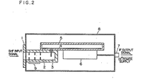
- FIG. 2 Another example of a conventional frequency converter is shown in Fig. 2, wherein same numbers are attached to the same parts as in Fig. 1.
- the converter in Fig. 2 is furnished with a waveguide type filter 9 in the rectangular waveguide unit 2 in order to satisfy the requirements of image suppression ratio and local oscillation signal leakage which were the defects in the conventional example shown in Fig. 1.
- the other constitution is similar to that of Fig. 1.
- the performances of the image suppression ratio and local oscillation frequency may be sufficiently satisfied, but the insertion loss of said filter 9 exerts adverse effects on the noise index as frequency converter, which is a serious defect.
- US-A-3349346 discloses a rectangular to circular waveguide transition in which the cross section of the waveguide gradually changes shape from rectangular to circular such that the axis of the rectangular portion is displaced with respect to the axis of the circular portion parallel to the direction of a longer side of the rectangular portion. Displacement of the axis of the waveguides in this way does not significantly improve the noise index characteristics.
- the present invention is intended to present a frequency converter which may satisfy not only the image suppression ratio and leakage prevention of local oscillation signal, but also the noise index characteristic.
- the object of the present invention is to present a frequency converter which is reduced in size while satisfying all of said image suppression ratio, local oscillation signal leakage prevention and noise index characteristics.
- the present invention provides a circular waveguide unit having an end to which a reception signal is applied, a rectangular waveguide unit and a circular-rectangular waveguide converter unit which connects to the other end of the circular waveguide unit to the rectangular waveguide unit to convert a transmission mode of the reception signal from TE" mode in the circular waveguide into a TE, o mode in the rectangular waveguide which is a main mode thereof; wherein the diameter of the circular waveguide unit is selected so that the cutoff frequency of the circular waveguide unit is lower than the frequency of the signal to be processed and higher than the local oscillation frequency so as to cause the circular waveguide unit to function as a high pass filter, characterised in that a rectangular waveguide-microstrip line converter unit is provided at the final end of the rectangular waveguide and a microwave integrated circuit is provided to process the reception signal fed there to through the rectangular waveguide-microstrip line converter unit to produce the processed signal as a signal of intermediate frequency, and the axis of said rectangular waveguide is arranged to be displaced with respect to the circular waveguide
- Figs. 1 and 2 are sectional views representing the constitution of conventional frequency converters for satellite broadcasting reception;
- Fig. 3 is a sectional view representing the constitution of frequency converter for satellite broadcast reception according to one of the embodiments of the present invention;
- Fig. 4 is a frequency distribution diagram showing the relation of frequencies of the frequency converter for satellite broadcast reception;
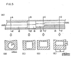
- Fig. 5A to E, Fig. 6a, b, and Fig. 7A to E are sectional views of examples of mutually different shapes of waveguide unit of respective converters;
- Fig. 8 is a sectional view of frequency converter for satellite broadcast reception in another embodiment;
- Fig. 9A, B are sectional views of the frequency converter of further embodiments; and
- Fig. 10 is a sectional views of an important part of the frequency converter of another embodiment.
- FIG. 3 One of the embodiments relates to a frequency converter for satellite broadcast reception, and an example of constitution thereof is shown in Fig. 3.
- input flange unit 11 circular waveguide unit 12, circular-rectangular waveguide converter unit 13, and rectangular waveguide unit 14 which possesses a rectangular waveguide-microstrip line converter unit 15 in its final end.
- numeral 16 is a microwave integrated circuit
- 17 is a shield case to accommodate said circuit
- 18 represents other circuits
- 19 is an output terminal
- 20 is an outer case.
- an SHF signal form a broadcast satellite is fed to the circular waveguide unit 12 through the input flange 11, and propagates through the circular waveguide unit 12, and is converted from the circular transmission mode to a rectangular transmission mode in the circular-rectangular waveguide converter unit 13 to be transmitted to the rectangular waveguide unit 14.
- the signal then propagates through the rectangular waveguide unit and enters the microwave integrated circuit 16 by way of rectangular waveguide-microstrip line converter unit 15 provided in the final end of the rectangular waveguide unit 14. After necessary signal processing in the microwave integrated circuit 16, it is delivered from the output terminal 19 as a signal of intermediate frequency.
- Fig. 4 An example of frequency relation of the signals of frequency converter of such constitution is shown in Fig. 4.
- the local oscillation frequency f L is set to 10.76 GHz
- the transmission mode of SHF signal of circular waveguide unit 12 in Fig. 3 is propagation in TE 11 mode which is the principal mode of circular waveguide.
- TE 11 mode is the principal mode of circular waveguide.
- the cutoff wavelength ⁇ c and cutoff frequency f c are expressed as follows.
- the attentuation a applied by the circular waveguide unit 12 to the signal of frequency lower than the cutoff frequency of circular waveguide unit 12 is where A is a free space wavelength.
- the attenuation is about 27 dB at local oscillation frqeuency f L and about 50 dB at image frequency f M .
- the circular waveguide unit 12 presents the characteristic of a high pass filter, and the characteristics of image suppression ratio and local oscillation frequency signal leakage required in the frequency converter are extremely improved.
- the internal wavelength ⁇ g of circular waveguide and characteristic impedance Z wc are expressed as follows. where: characteristic impedance in free space.
- the circular-rectangular waveguide converter unit 13 is provided to convert the transmission mode of signal from circular mode TE 11 to TE io which is the principal mode of rectangular waveguide.
- the section of the rectangular waveguide unit 14 after rectangular conversion is shown in section D-D' in Fig. 5E.
- the internal wavelength ⁇ g and characteristic impedance Z WR of the rectangular waveguide unit 14 having this section are expressed as follows.
- the rectangular waveguide-microstrip line converter unit 15 is provided, and the rectangular waveguide-microstrip line conversion is effected easily, and the signals from the satellite are introduced into the microwave integrated circuit 16.
- a particularly notable feature of the present invention is that not only the circular-rectangular converting function is provided, but also the axis of circular waveguide unit 12 and that of rectangular waveguide unit 14 are deviated in a direction parallel to a shorter side of the rectangular waveguide unit 14 by properly selecting the dimensions of the circular-rectangular converter unit.
- the TE" mode of circular waveguide unit 12 is first converted to the mode of rectangular waveguide unit possessing the characteristic impedance of high impedance by the step converter 13 of the first step, and is then converted to the rectangular transmission mode TE 10 of low impedance gradually through the second step converter 13'.
- Fig. 6b shows, by way of explanation a waveguide unit of circular-rectangular waveguide conversion, in which, the axis of the circular waveguide unit 12 and that of the rectangular waveguide unit 14 coincide with each other.
- Fig. 6a shows, for comparison, waveguide units of a frequency converter according to the present invention.
- the dimension L2 is enlarged when applied to a frequency converter, and the attenuation of signal becomes larger as compared with the dimension of L1 in the rectangular waveguide-microstrip line converter unit 15, shown in Fig. 6a.
- This attenuation may give rise to deterioration of noise index characteristic required in the converter.
- the circular-rectangular waveguide converter unit 13 is provided with both circular-rectangular waveguide converting function and the function to move the axis of the waveguide parallel in the direction of shorter side of the rectangular waveguide, and the dimension of L1 in Fig. 6a is minimized to prevent deterioration of noise index.
- FIG. 7A to E An embodiment using taper waveguide is shown in Fig. 7A to E.
- the mode is converted from circular to rectangular by a taper waveguide 13A having a certain inclination 0 against the axis of the circular waveguide unit 12, and the axis of circular waveguide unit 12 and that of rectangular waveguide unit 14 are simultaneously moved parallel.
- a converter unit which is a rectangular-circular waveguide converter unit 22
- a rectangular waveguide unit 21 is provided before this rectangular-circular waveguide converter unit 22.
- the reception signal fed from the input flange unit 11 propagates through the rectangular waveguide unit 21 in TE 10 mode, and is converted to TE" mode of the circular waveguide unit 12 in the rectangular-circular waveguide converter unit 22, and is applied into the circular waveguide unit 12 which acts as a high pass filter.
- the subsequent operation is same as in the explanation of Fig. 3.
- Fig. 9A, B Other embodiment is shown in Fig. 9A, B.
- This embodiment is intended to satisfy the image suppression ratio, leakage prevention of local oscillation signal, and noise index characteristic, and also to reduce the size.
- the H-wall of circular-rectangular waveguide converter unit 13 and rectangular waveguide converter unit 14 in Fig. 3 is composed of shield case 17 of microwave integrated circuit 16.
- the constitution of the other parts is the same as in Fig. 3.
- the dimension L3 in the rectangular-microstrip line converter unit 15 may be further reduced, and the signal attenuation in this part may be held to a minimum, and the size of the equipment may be reduced without deteriorating the noise index characteristic.
- FIG. 10 Another embodiment is shown in Fig. 10.
- the H-wall of circular-rectangular waveguide converter unit 13 and rectangular waveguide unit 14 in Fig. 3 is composed of grounding plate 16A of dielectric substrate as used in the microwave integrated circuit 16.
- the dimension L4 may be further decreased, so that the size may be much smaller.
- numeral 24 in Figs. 9 and 10 refers to a probe set up on the microwave integrated circuit 16.
- a high performance frequency converter satisfying all the requirements of image suppression ratio, leakage prevention of local oscillation signal, and noise index characteristic may be obtained, and it is particularly suitable for use in satellite broadcast reception.
Landscapes
- Engineering & Computer Science (AREA)
- Radar, Positioning & Navigation (AREA)
- Remote Sensing (AREA)
- Physics & Mathematics (AREA)
- Electromagnetism (AREA)
- Power Engineering (AREA)
- Input Circuits Of Receivers And Coupling Of Receivers And Audio Equipment (AREA)
- Structure Of Receivers (AREA)
- Waveguide Switches, Polarizers, And Phase Shifters (AREA)
Claims (3)
Applications Claiming Priority (4)
| Application Number | Priority Date | Filing Date | Title |
|---|---|---|---|
| JP8429/83 | 1983-01-20 | ||
| JP58008429A JPS59133714A (ja) | 1983-01-20 | 1983-01-20 | 周波数変換装置 |
| JP26532/83 | 1983-02-18 | ||
| JP58026532A JPS59152702A (ja) | 1983-02-18 | 1983-02-18 | マイクロ波装置 |
Publications (3)
| Publication Number | Publication Date |
|---|---|
| EP0131633A1 EP0131633A1 (de) | 1985-01-23 |
| EP0131633A4 EP0131633A4 (de) | 1985-06-26 |
| EP0131633B1 true EP0131633B1 (de) | 1988-10-26 |
Family
ID=26342941
Family Applications (1)
| Application Number | Title | Priority Date | Filing Date |
|---|---|---|---|
| EP84900532A Expired EP0131633B1 (de) | 1983-01-20 | 1984-01-13 | Frequenzumwandler |
Country Status (5)
| Country | Link |
|---|---|
| US (1) | US4608713A (de) |
| EP (1) | EP0131633B1 (de) |
| CA (1) | CA1207397A (de) |
| DE (1) | DE3474888D1 (de) |
| WO (1) | WO1984003008A1 (de) |
Families Citing this family (22)
| Publication number | Priority date | Publication date | Assignee | Title |
|---|---|---|---|---|
| ES8700505A1 (es) * | 1985-08-09 | 1986-10-01 | Mier Allende S A | Perfeccionamientos en la construccion de una unidad externa para foco de antena de microondas |
| FR2591407B1 (fr) * | 1985-12-10 | 1988-08-05 | Loire Electronique | Dispositif de reception, a guide d'onde et circuits superheterodynes, de deux signaux hyperfrequences a polarisation de sens inverses |
| FR2591406B1 (fr) * | 1985-12-10 | 1989-01-13 | Loire Electronique | Dispositif de reception simultanee de deux signaux hyperfrequences a polarisation circulaire de sens inverses |
| DE3619220A1 (de) * | 1986-06-07 | 1988-02-18 | Kolbe & Co Hans | Konvertersystem |
| BE905593A (nl) * | 1986-10-10 | 1987-02-02 | Devloo Frans Victor | Golfgeleider hoogfrequente convertor. |
| JPH0174613U (de) * | 1987-07-06 | 1989-05-19 | ||
| GB2226919B (en) * | 1988-11-12 | 1993-07-21 | Matsushita Electric Works Ltd | Converter for planar antenna |
| JP3366031B2 (ja) * | 1992-11-26 | 2003-01-14 | 松下電器産業株式会社 | 導波管−マイクロストリップ変換器 |
| AU690980B2 (en) * | 1994-05-06 | 1998-05-07 | Koninklijke Philips Electronics N.V. | Microwave transmission system |
| DE19505860A1 (de) * | 1995-02-21 | 1996-08-22 | Philips Patentverwaltung | Konverter |
| US5539361A (en) * | 1995-05-31 | 1996-07-23 | The United States Of America As Represented By The Secretary Of The Air Force | Electromagnetic wave transfer |
| JP2002246813A (ja) * | 2001-02-19 | 2002-08-30 | Alps Electric Co Ltd | マイクロ波機器の導波管構造 |
| US7855612B2 (en) * | 2007-10-18 | 2010-12-21 | Viasat, Inc. | Direct coaxial interface for circuits |
| US7625131B2 (en) | 2007-05-02 | 2009-12-01 | Viasat, Inc. | Interface for waveguide pin launch |
| US7812686B2 (en) * | 2008-02-28 | 2010-10-12 | Viasat, Inc. | Adjustable low-loss interface |
| US7782156B2 (en) * | 2007-09-11 | 2010-08-24 | Viasat, Inc. | Low-loss interface |
| WO2009114731A2 (en) | 2008-03-13 | 2009-09-17 | Viasat, Inc. | Multi-level power amplification system |
| CN102374557B (zh) * | 2011-10-31 | 2016-08-03 | 广东美的厨房电器制造有限公司 | 半导体微波炉的微波馈入结构 |
| WO2018029846A1 (ja) * | 2016-08-12 | 2018-02-15 | 三菱電機株式会社 | 導波管ストリップ線路変換器及び給電回路 |
| EP3450931B1 (de) * | 2017-08-28 | 2022-10-05 | VEGA Grieshaber KG | Hohlleitereinkopplung für ein füllstandradar |
| EP3657597A1 (de) * | 2018-11-22 | 2020-05-27 | Airbus Oneweb Satellites SAS | Aktives wellenleiterübergangs- und hf-signalkommunikationssystem |
| DE102021200196A1 (de) * | 2021-01-12 | 2022-07-14 | Robert Bosch Gesellschaft mit beschränkter Haftung | Radarsensor |
Citations (4)
| Publication number | Priority date | Publication date | Assignee | Title |
|---|---|---|---|---|
| JPS5141283B1 (de) * | 1970-08-05 | 1976-11-09 | ||
| JPS5141306B1 (de) * | 1969-06-16 | 1976-11-09 | ||
| JPS5225054B2 (de) * | 1972-04-03 | 1977-07-05 | ||
| JPS5471916A (en) * | 1977-11-18 | 1979-06-08 | Matsushita Electric Ind Co Ltd | Microwave frequency converter circuit |
Family Cites Families (12)
| Publication number | Priority date | Publication date | Assignee | Title |
|---|---|---|---|---|
| US2816271A (en) * | 1950-11-22 | 1957-12-10 | Gen Electric | Microwave mode converter |
| US3230484A (en) * | 1963-10-22 | 1966-01-18 | Lipetz Nathan | Waveguide transition between rectangular and circular waveguides |
| US3349346A (en) * | 1965-03-08 | 1967-10-24 | Gen Electric | Rectangular to circular waveguide transition |
| JPS5141502B1 (de) * | 1971-07-19 | 1976-11-10 | ||
| JPS5141283A (ja) * | 1974-10-02 | 1976-04-07 | Misao Eguchi | Mizumushibojoyohakimonozai |
| JPS5141306A (en) * | 1974-10-04 | 1976-04-07 | Gaf Corp | pvc hannokikarahaikisareru enkabinirunokaishu narabini seiseiho |
| JPS5225054A (en) * | 1975-08-18 | 1977-02-24 | Hiroshi Katayama | Method of processing and producing edible laver |
| US4000469A (en) * | 1975-12-11 | 1976-12-28 | Bell Telephone Laboratories, Incorporated | Combination waveguide and stripline downconverter |
| FR2450507A1 (fr) * | 1979-03-01 | 1980-09-26 | Lignes Telegraph Telephon | Melangeur hyperfrequence |
| US4420756A (en) * | 1981-01-19 | 1983-12-13 | Trw Inc. | Multi-mode tracking antenna feed system |
| US4418430A (en) * | 1981-10-05 | 1983-11-29 | General Dynamics, Pomona Division | Millimeter-wavelength overmode balanced mixer |
| WO2000007437A1 (en) * | 1998-08-06 | 2000-02-17 | Rutgers, The State University Of New Jersey | A method of identifying and recovering products exuded from a plant |
-
1984
- 1984-01-13 EP EP84900532A patent/EP0131633B1/de not_active Expired
- 1984-01-13 DE DE8484900532T patent/DE3474888D1/de not_active Expired
- 1984-01-13 WO PCT/JP1984/000004 patent/WO1984003008A1/ja not_active Ceased
- 1984-01-19 CA CA000445664A patent/CA1207397A/en not_active Expired
- 1984-08-29 US US06/642,350 patent/US4608713A/en not_active Expired - Fee Related
Patent Citations (4)
| Publication number | Priority date | Publication date | Assignee | Title |
|---|---|---|---|---|
| JPS5141306B1 (de) * | 1969-06-16 | 1976-11-09 | ||
| JPS5141283B1 (de) * | 1970-08-05 | 1976-11-09 | ||
| JPS5225054B2 (de) * | 1972-04-03 | 1977-07-05 | ||
| JPS5471916A (en) * | 1977-11-18 | 1979-06-08 | Matsushita Electric Ind Co Ltd | Microwave frequency converter circuit |
Non-Patent Citations (2)
| Title |
|---|
| PATENTS ABSTRACTS OF JAPAN, vol. 1, no. 72, 13th July 1977, page 750E77; & JP - A - 52 9347 (MATSUSHITA DENKI SANGYO K.K.) 24-01-1977 * |
| PATENTS ABSTRACTS OF JAPAN, vol. 1, no. 72, 13th July 1977, page 750E77; & JP - A - 52 9348 (MATSUSHITA DENKI SANGYO K.K.) 24-01-1977 * |
Also Published As
| Publication number | Publication date |
|---|---|
| EP0131633A1 (de) | 1985-01-23 |
| CA1207397A (en) | 1986-07-08 |
| US4608713A (en) | 1986-08-26 |
| EP0131633A4 (de) | 1985-06-26 |
| DE3474888D1 (en) | 1988-12-01 |
| WO1984003008A1 (en) | 1984-08-02 |
Similar Documents
| Publication | Publication Date | Title |
|---|---|---|
| US4608713A (en) | Frequency converter | |
| US4168479A (en) | Millimeter wave MIC diplexer | |
| US7019603B2 (en) | Waveguide type ortho mode transducer | |
| EP0127402B1 (de) | Überdimensioniertes Hohlleiterübergangsstück mit einem Phasenverschiebungsteil | |
| JPS58172002A (ja) | 2周波、2偏波無線信号分離用導波管 | |
| EP1291955B1 (de) | Wellenleiter-gruppenverzweigungsfilter | |
| EP0905814A2 (de) | Übergang zwischen Übertragungsleitung und Hohlleiter | |
| CA2042962C (en) | Orthomode transducer between a circular waveguide and a coaxial cable | |
| US4449108A (en) | Band-stop filter for VHF-UHF band | |
| EP0928040B1 (de) | Sender/Empfänger für elektromagnetische Wellen | |
| US7332982B2 (en) | Waveguide diplexer of electric plane T-junction structure with resonant iris | |
| US4622524A (en) | Dual band polarization filter comprising orthogonally oriented fin-type conductors | |
| EP1492193B1 (de) | Hochfrequenzmodul und antenneneinrichtung | |
| JPS6014502A (ja) | 4ポ−ト回路 | |
| JPH06511119A (ja) | 狭帯域通過・広帯域消去フィルタ | |
| US4533919A (en) | Corrugated antenna feed arrangement | |
| US4147980A (en) | Redundant rf system for space application | |
| JPH08204404A (ja) | 導波管高域通過フィルタ | |
| GB2107129A (en) | Broad-band slot-coupled diplexer | |
| JP2803646B2 (ja) | 導波管型分波器 | |
| CN117977137B (zh) | 一种组装式正交模转换器-滤波器组件及电子设备 | |
| JPS59133714A (ja) | 周波数変換装置 | |
| JP3185008B2 (ja) | 直交偏分波器 | |
| JPH01273401A (ja) | 分波器 | |
| JPS6112128A (ja) | 不要波抑圧コンバ−タ |
Legal Events
| Date | Code | Title | Description |
|---|---|---|---|
| PUAI | Public reference made under article 153(3) epc to a published international application that has entered the european phase |
Free format text: ORIGINAL CODE: 0009012 |
|
| 17P | Request for examination filed |
Effective date: 19840906 |
|
| AK | Designated contracting states |
Designated state(s): DE FR GB |
|
| 17Q | First examination report despatched |
Effective date: 19870605 |
|
| GRAA | (expected) grant |
Free format text: ORIGINAL CODE: 0009210 |
|
| AK | Designated contracting states |
Kind code of ref document: B1 Designated state(s): DE FR GB |
|
| REF | Corresponds to: |
Ref document number: 3474888 Country of ref document: DE Date of ref document: 19881201 |
|
| ET | Fr: translation filed | ||
| PLBE | No opposition filed within time limit |
Free format text: ORIGINAL CODE: 0009261 |
|
| STAA | Information on the status of an ep patent application or granted ep patent |
Free format text: STATUS: NO OPPOSITION FILED WITHIN TIME LIMIT |
|
| 26N | No opposition filed | ||
| PGFP | Annual fee paid to national office [announced via postgrant information from national office to epo] |
Ref country code: GB Payment date: 19940105 Year of fee payment: 11 |
|
| PGFP | Annual fee paid to national office [announced via postgrant information from national office to epo] |
Ref country code: DE Payment date: 19940110 Year of fee payment: 11 |
|
| PGFP | Annual fee paid to national office [announced via postgrant information from national office to epo] |
Ref country code: FR Payment date: 19940111 Year of fee payment: 11 |
|
| PG25 | Lapsed in a contracting state [announced via postgrant information from national office to epo] |
Ref country code: GB Effective date: 19950113 |
|
| GBPC | Gb: european patent ceased through non-payment of renewal fee |
Effective date: 19950113 |
|
| PG25 | Lapsed in a contracting state [announced via postgrant information from national office to epo] |
Ref country code: FR Effective date: 19950929 |
|
| PG25 | Lapsed in a contracting state [announced via postgrant information from national office to epo] |
Ref country code: DE Effective date: 19951003 |
|
| REG | Reference to a national code |
Ref country code: FR Ref legal event code: ST |