EP0131815A1 - Dispositif pour moteur à courant alternatif - Google Patents
Dispositif pour moteur à courant alternatif Download PDFInfo
- Publication number
- EP0131815A1 EP0131815A1 EP84107494A EP84107494A EP0131815A1 EP 0131815 A1 EP0131815 A1 EP 0131815A1 EP 84107494 A EP84107494 A EP 84107494A EP 84107494 A EP84107494 A EP 84107494A EP 0131815 A1 EP0131815 A1 EP 0131815A1
- Authority
- EP
- European Patent Office
- Prior art keywords
- filter
- frequency
- alternating current
- current
- chokes
- Prior art date
- Legal status (The legal status is an assumption and is not a legal conclusion. Google has not performed a legal analysis and makes no representation as to the accuracy of the status listed.)
- Granted
Links
- 230000001360 synchronised effect Effects 0.000 claims abstract description 12
- 239000003990 capacitor Substances 0.000 claims description 10
- 230000005294 ferromagnetic effect Effects 0.000 claims description 7
- 230000001419 dependent effect Effects 0.000 claims description 6
- 239000004020 conductor Substances 0.000 claims description 5
- 238000001914 filtration Methods 0.000 claims description 3
- 229920006395 saturated elastomer Polymers 0.000 claims description 3
- 230000010355 oscillation Effects 0.000 claims 1
- 230000002238 attenuated effect Effects 0.000 abstract 1
- 230000000694 effects Effects 0.000 description 4
- 238000013016 damping Methods 0.000 description 2
- 230000005540 biological transmission Effects 0.000 description 1
- 239000004568 cement Substances 0.000 description 1
- 238000001816 cooling Methods 0.000 description 1
- 238000010586 diagram Methods 0.000 description 1
- 238000010438 heat treatment Methods 0.000 description 1
- 230000005415 magnetization Effects 0.000 description 1
- 230000010349 pulsation Effects 0.000 description 1
- XLYOFNOQVPJJNP-UHFFFAOYSA-N water Substances O XLYOFNOQVPJJNP-UHFFFAOYSA-N 0.000 description 1
Images
Classifications
-
- H—ELECTRICITY
- H02—GENERATION; CONVERSION OR DISTRIBUTION OF ELECTRIC POWER
- H02M—APPARATUS FOR CONVERSION BETWEEN AC AND AC, BETWEEN AC AND DC, OR BETWEEN DC AND DC, AND FOR USE WITH MAINS OR SIMILAR POWER SUPPLY SYSTEMS; CONVERSION OF DC OR AC INPUT POWER INTO SURGE OUTPUT POWER; CONTROL OR REGULATION THEREOF
- H02M1/00—Details of apparatus for conversion
- H02M1/12—Arrangements for reducing harmonics from AC input or output
-
- H—ELECTRICITY
- H02—GENERATION; CONVERSION OR DISTRIBUTION OF ELECTRIC POWER
- H02P—CONTROL OR REGULATION OF ELECTRIC MOTORS, ELECTRIC GENERATORS OR DYNAMO-ELECTRIC CONVERTERS; CONTROLLING TRANSFORMERS, REACTORS OR CHOKE COILS
- H02P25/00—Arrangements or methods for the control of AC motors characterised by the kind of AC motor or by structural details
- H02P25/02—Arrangements or methods for the control of AC motors characterised by the kind of AC motor or by structural details characterised by the kind of motor
- H02P25/022—Synchronous motors
- H02P25/024—Synchronous motors controlled by supply frequency
-
- Y—GENERAL TAGGING OF NEW TECHNOLOGICAL DEVELOPMENTS; GENERAL TAGGING OF CROSS-SECTIONAL TECHNOLOGIES SPANNING OVER SEVERAL SECTIONS OF THE IPC; TECHNICAL SUBJECTS COVERED BY FORMER USPC CROSS-REFERENCE ART COLLECTIONS [XRACs] AND DIGESTS
- Y02—TECHNOLOGIES OR APPLICATIONS FOR MITIGATION OR ADAPTATION AGAINST CLIMATE CHANGE
- Y02P—CLIMATE CHANGE MITIGATION TECHNOLOGIES IN THE PRODUCTION OR PROCESSING OF GOODS
- Y02P80/00—Climate change mitigation technologies for sector-wide applications
- Y02P80/10—Efficient use of energy, e.g. using compressed air or pressurized fluid as energy carrier
Definitions
- the invention is based on an AC machine drive according to the preamble of patent claim 1.
- the invention relates to a prior art of AC machine drives, as described in the Swiss company magazine Brown Boveri Mitt. 10 (1980) pp. 577-583.
- drives of synchronous motors are specified, which are fed by 6- and 12-pulse frequency converters.
- the 5th and 7th harmonics on the line and motor side are avoided using 12-pulse frequency converters.
- To start synchronous motors with a very high load or counter torque of the loading machine it is known to use a 24-pulse inverter circuit. Current harmonics and thus the heating of the rotor can be further reduced by this measure.
- Inverters enable the generation of an alternating current of a predeterminable number of phases with a variable frequency and thus a speed-controlled drive without the interposition of a transmission gear.
- the alternating current generated is not sinusoidal, as is required by the alternating current motors, so that it leads to unsteady running, undesirable pendulum torques, increased rotor temperatures and finally to a relatively low efficiency of the motor if no or insufficient precautions are taken. to make the alternating current sinusoidal.
- Such frequency variable drives are e.g. used for boiler feed pumps, cement tube mills, turbo compressors, mine conveyor drives, excavator drives, gas turbines, converter synchronous generator systems for wind and water power plants and for fans.
- the invention solves the task of reducing pendulum torques in AC machines and improving the efficiency of AC machines which are fed by variable frequency converters.
- the effect of the measure claimed thereby is that the AC machines vibrate less and therefore run more smoothly.
- the expenditure for cooling the rotor can be reduced.
- the efficiency of the machines can be improved by several percent and thus energy can be saved to a considerable extent, since the drives are mainly considered for outputs over 100 kW, for synchronous machines for outputs over 2 MW.
- a 6-pulse inverter circuit with a frequency-variable filter proved to be superior to a 12-pulse inverter circuit without a frequency-variable filter in terms of efficiency, cozy, price, weight, dimensions of the AC machine and pulsation moments.
- the effect is achieved with relatively few switching elements by means of suction circuits with a suitably dimensioned, frequency-dependent ohmic resistor.
- suction circuits with a suitably dimensioned, frequency-dependent ohmic resistor.
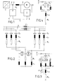
- Fig. 1, 1 designates a frequency converter, which is used to convert an alternating current of certain frequency and number of phases into an alternating current with the same or different number of phases and a different, variable frequency.
- a frequency converter with a DC intermediate circuit is preferably used, which draws energy from an AC or three-phase network via a rectifier and feeds an AC load with 6-pulse AC via a network or self-extinguished inverter.
- the current in the DC link is kept constant with the help of a choke.
- the frequency converter 1 feeds an alternating current machine M via alternating current lines 2, the number of which is equal to the number of phases of the alternating current. For outputs up to 2 MW, asynchronous machines are inexpensive to use and for outputs over 2 MW synchronous machines.
- a commutation choke L k is connected in each AC line 2 to limit the change in time of the alternating current di / dt.
- a variable frequency filter 6 is provided, which filters out or short-circuits undesired harmonics in the alternating current supplied by the frequency converter 1, so that the alternating current machine receives an almost sinusoidal alternating current over a predefinable frequency or speed range. This can improve the efficiency of the AC machine.
- the frequency of the AC voltage generated by the frequency converter 1 is changed during operation in accordance with the speed required by the AC machine, in particular by a synchronous motor.
- the frequencies of the harmonics to be filtered out also change in accordance with this frequency change.
- the frequency variable filter 6 not only filters out the harmonics for the nominal frequency of the synchronous motor, but also for a predeterminable frequency range in which the synchronous motor is predominantly operated.
- the frequency of the alternating current is measured on the AC line 2 by means of a frequency meter 3 and compared with at least one predefinable limit frequency in a frequency limit value detector 4 connected to the frequency meter. If the measured frequency exceeds a predeterminable limit value, a switching signal is transmitted to the frequency-variable filter 6 via a switching signal line 5 and actuates an AC switch there.
- FIG. 2 shows a frequency-variable filter 6 according to FIG. 1.
- a filter for the 5th and 7th harmonic is connected to each phase line R, S, T of the AC lines 2.
- c 5 and C 7 are filter capacitors, with L 5 , L 7 , L7 filter chokes, with R 5 and R 7 frequency-dependent resistors of the associated filter chokes and with 7 and 8 AC switch designated with anti-parallel connected thyristors.
- the indices 5 and 7 denote the harmonic of the filter.
- the filters connected on the input side to the same phase conductor are connected to one another on the output side.
- filter line chokes L7 indicated by dashed lines can also be used, which are then switched on at the point shown in the phase lines R, S, T and at the same time act as commutation chokes.
- L are connected chokes and R their ohmic x x frequency-dependent resistors.
- the AC switches 7 and 8 can be switched as a function of a switching signal from the frequency limit value detector 4. If the two AC switches are open, a connection choke L is connected in series for each phase to the outputs of the filters of this phase. If the AC switches 7 and 8 are closed, the connection chokes are short-circuited and the outputs of the phase filters of all phases are mutually exclusive. An output of each cut-in choke L x is also connected to an output of every other cut-in choke L.
- n of the harmonics to be filtered out results from:
- U E RMS value of the mains voltage fundamental
- I n RMS value of the nth current harmonic, and for one power be designed.
- the capacitor power has a minimum for
- the inductance for the respective harmonic can be calculated from equation (3).
- the amount of the alternating current resistance, ie the impedance of the alternating current machine Z M , must be taken into account when calculating In according to: where 1 0 is the ideal average DC component of the alternating current and Z s is the total impedance for which the following applies: With and R n0 , R n1 and R n2 are constants. In a first approximation, R n2 can be neglected in the calculation.
- the best attenuation for the 5th and 7th harmonic for the 100 Hz fundamental and an effective attenuation in the frequency range from about 90 Hz to 108 Hz is achieved. If, for example, the frequency of the alternating current falls below the frequency limit value 90 Hz, the alternating current switches 7 and 8 are switched off and the connecting chokes L x are thus connected to the suction circuits of each alternating current phase.
- the connection chokes L are dimensioned with their inductance x in such a way that they effect optimal damping of both the 5th and the 7th harmonic for about 86 Hz. This allows effective attenuation of the undesirable harmonics from about 80 Hz to 108 Hz Harmonics and thus good efficiency and a reduction in the alternating torque of the AC machine can be achieved.
- Fig. 3 shows a suction circuit connected on the input side to one of the three-phase lines R, S, T for an n.
- Harmonic harmonic in which instead of a single filter choke line main filter choke L n0 with several taps in series with three additional filter chokes L nl , L n2 , L n3 are provided for the nth harmonic, the three additional filter chokes being connected in parallel with one another.
- the additional filter chokes L n2 and L n3 are each connected in parallel via series-connected alternating current switches 10 and 9 with thyristors connected in parallel.
- R n denotes the frequency - dependent ohmic resistance of the filter chokes and C n a filter capacitor for the nth harmonic.
- the suction circuit is grounded on the output side.
- the taps of the main filter choke L nO shown in broken lines, are connected to the grounded output of the main filter choke via an electronic step switch 11.
- the dashed lines indicate that this tap changer can be provided as an alternative to the additional filter chokes L n2 and L n3 or additionally.
- the frequency range in which the suction circuit has a damping effect can be changed by gradually reducing and increasing the suction circuit inductance.
- the switching on and off of additional filter chokes and main filter choke sections is carried out by switching signals depending on predeterminable frequency limit values.
- Fig. 4 shows a suction circuit connected on the input side to one of the three three-phase lines R, S, T for an n.
- Harmonic harmonic which is grounded on the output side and a filter capacitor C, a main filter choke L n0 and two in series and one below the other the parallel connected additional filter chokes L na and L nb with ferromagnetic core.
- diodes 12 and 13 are connected, which are polarized in the same direction, so that only the positive current half-wave through the additional filter choke L na and only through the additional filter choke L nb the negative current semi-oscillation can happen.
- the additional filter chokes L na and L nb are operated in the vicinity of the saturation range of the ferromagnetic cores. Their inductances are dimensioned such that the ferromagnetic cores for frequencies below the frequencies to be filtered out are not saturated and above these frequencies, which corresponds to a reduction in the inductance. This enables a continuous change in the resonance frequency of the suction circuit.
- R again denotes the frequency-dependent ohmic resistance of the filter chokes.
- the invention is of course not limited to what is shown in the drawings.
- a gradual change in the resonance frequency of the suction circuits can also take place by a step-by-step change in the capacitance of the filter capacitors instead of a step-by-step change in the inductance.
- Several capacitors connected in parallel are used, which can be switched on and off in stages using AC switches. This measure can also be used in addition to the measures described to change the inductance of the filter chokes.
- frequency-variable filters can be produced in particular for nominal frequencies in the range from 4 Hz and 200 Hz, which are of particular interest for frequency-variable drives.
- the filters are provided with a symmetry protection known per se and an overvoltage protection, which are not the subject of the invention and are therefore not shown.
Landscapes
- Power Engineering (AREA)
- Engineering & Computer Science (AREA)
- Ac-Ac Conversion (AREA)
- Power Conversion In General (AREA)
- Control Of Ac Motors In General (AREA)
- Control Of Motors That Do Not Use Commutators (AREA)
- Valve Device For Special Equipments (AREA)
- Power Steering Mechanism (AREA)
- Soil Working Implements (AREA)
- Forklifts And Lifting Vehicles (AREA)
- Preliminary Treatment Of Fibers (AREA)
- Vending Machines For Individual Products (AREA)
- Control Of Multiple Motors (AREA)
Priority Applications (1)
| Application Number | Priority Date | Filing Date | Title |
|---|---|---|---|
| AT84107494T ATE21982T1 (de) | 1983-07-13 | 1984-06-28 | Wechselstrommaschinenantrieb. |
Applications Claiming Priority (2)
| Application Number | Priority Date | Filing Date | Title |
|---|---|---|---|
| CH3831/83 | 1983-07-13 | ||
| CH383183 | 1983-07-13 |
Publications (2)
| Publication Number | Publication Date |
|---|---|
| EP0131815A1 true EP0131815A1 (fr) | 1985-01-23 |
| EP0131815B1 EP0131815B1 (fr) | 1986-09-03 |
Family
ID=4264400
Family Applications (1)
| Application Number | Title | Priority Date | Filing Date |
|---|---|---|---|
| EP84107494A Expired EP0131815B1 (fr) | 1983-07-13 | 1984-06-28 | Dispositif pour moteur à courant alternatif |
Country Status (8)
| Country | Link |
|---|---|
| US (1) | US4623830A (fr) |
| EP (1) | EP0131815B1 (fr) |
| AT (1) | ATE21982T1 (fr) |
| CA (1) | CA1218694A (fr) |
| DE (1) | DE3460615D1 (fr) |
| ES (1) | ES8506949A1 (fr) |
| IN (1) | IN161365B (fr) |
| ZA (1) | ZA845346B (fr) |
Cited By (6)
| Publication number | Priority date | Publication date | Assignee | Title |
|---|---|---|---|---|
| DE3832922A1 (de) * | 1987-09-28 | 1989-04-06 | Toshiba Kawasaki Kk | Vorrichtung zur energieumformung mit harmonischenfilterung |
| DE102005019215B4 (de) * | 2005-04-25 | 2008-05-15 | Siemens Ag | Ausgangsfilter für einen gepulsten Stromrichter |
| WO2009146961A1 (fr) * | 2008-06-05 | 2009-12-10 | Siemens Aktiengesellschaft | Filtre passe-bas triphasé avec pertes |
| DE102012216266A1 (de) * | 2012-09-13 | 2014-03-13 | Siemens Aktiengesellschaft | Verfahren und Vorrichtung zum Herstellen eines Filters und Filter |
| WO2019057736A1 (fr) * | 2017-09-19 | 2019-03-28 | Wobben Properties Gmbh | Installation d'énergie éolienne à équipement de filtre dépendant de la puissance |
| WO2020084064A1 (fr) * | 2018-10-26 | 2020-04-30 | Maschinenfabrik Reinhausen Gmbh | Dispositif de filtrage pour un réseau d'énergie, utilisation d'un agencement de bobines et procédé de fonctionnement d'un dispositif de filtrage |
Families Citing this family (18)
| Publication number | Priority date | Publication date | Assignee | Title |
|---|---|---|---|---|
| US4761703A (en) * | 1987-08-31 | 1988-08-02 | Electric Power Research Institute, Inc. | Rotor fault detector for induction motors |
| DE59004640D1 (de) * | 1989-11-13 | 1994-03-24 | Siemens Ag | Verfahren zur korrektur eines ermittelten, fehlerbehafteten istwertes eines oberschwingungsbehafteten signals und schaltungsanordnung zur durchführung dieses verfahrens. |
| DE4132340A1 (de) * | 1991-08-26 | 1993-03-04 | Loher Ag | Schaltungsanordnung mit einem stromsteller und mit einem motor, insbesondere mit einem drehstromsteller und mit einem drehstrom-asynchronmotor |
| SE9704421D0 (sv) * | 1997-02-03 | 1997-11-28 | Asea Brown Boveri | Seriekompensering av elektrisk växelströmsmaskin |
| DE19814059A1 (de) * | 1998-03-30 | 1999-10-07 | Asea Brown Boveri | Lastseitige Filteranordnung für eine Stromrichter-Schaltungsanordnung |
| DE19846637A1 (de) | 1998-10-09 | 2000-04-13 | Heidenhain Gmbh Dr Johannes | Verfahren und Schaltungsanordnung zur automatischen Parametrierung eines schnellen digitalen Drehzahlregelkreises |
| JP3499786B2 (ja) * | 1999-11-25 | 2004-02-23 | 株式会社日立製作所 | 超高速永久磁石式回転電機システム |
| JP2003219691A (ja) * | 2002-01-17 | 2003-07-31 | Meidensha Corp | 永久磁石式同期モータの駆動システム及びその試験方法 |
| GB0314550D0 (en) * | 2003-06-21 | 2003-07-30 | Weatherford Lamb | Electric submersible pumps |
| US7701106B2 (en) * | 2003-06-21 | 2010-04-20 | Oilfield Equipment Development Center Limited | Electric submersible pumps |
| GB0314553D0 (en) * | 2003-06-21 | 2003-07-30 | Weatherford Lamb | Electric submersible pumps |
| GB0426585D0 (en) * | 2004-12-06 | 2005-01-05 | Weatherford Lamb | Electrical connector and socket assemblies |
| US20080080991A1 (en) * | 2006-09-28 | 2008-04-03 | Michael Andrew Yuratich | Electrical submersible pump |
| US8106540B2 (en) * | 2008-10-10 | 2012-01-31 | General Electric Company | Compensation system for power transmission |
| US10256757B1 (en) * | 2012-05-15 | 2019-04-09 | The Boeing Company | Apparatus and methods to damp electromechanical device vibration |
| US9293248B2 (en) * | 2012-12-12 | 2016-03-22 | Raytheon Company | Methods and apparatus for EMI filter having switched capacitance based on loading |
| US11018610B2 (en) | 2017-01-27 | 2021-05-25 | Franklin Electric Co., Inc. | Motor drive system and method |
| US10877097B2 (en) * | 2019-02-06 | 2020-12-29 | Power Standard Labs, Inc. | DC monitoring system for variable frequency drives |
Citations (3)
| Publication number | Priority date | Publication date | Assignee | Title |
|---|---|---|---|---|
| US3501686A (en) * | 1968-08-22 | 1970-03-17 | Asea Ab | Control device for a filter circuit for a static inverter |
| DE2852066A1 (de) * | 1978-11-29 | 1980-06-12 | Licentia Gmbh | Elektrisches filter mit saugkreischarakteristik |
| DE2905408A1 (de) * | 1979-02-09 | 1980-08-21 | Licentia Gmbh | Thyristorgeschaltete leistungskondensatoren zur blindstromkompensation |
Family Cites Families (8)
| Publication number | Priority date | Publication date | Assignee | Title |
|---|---|---|---|---|
| US2241832A (en) | 1940-05-07 | 1941-05-13 | Hugo W Wahlquist | Method and apparatus for reducing harmonics in power systems |
| CA848023A (en) | 1966-08-31 | 1970-07-28 | D. Kaiser Francis | High voltage direct current transmission systems |
| US3555291A (en) | 1968-05-16 | 1971-01-12 | Gen Electric | Power system filter |
| GB1450931A (en) | 1973-01-17 | 1976-09-29 | Ass Elect Ind | Frequency selective damping circuits for use in ac power systems |
| US3859542A (en) | 1973-09-12 | 1975-01-07 | Inductotherm Corp | Harmonic and power factor compensation means and method for power systems controlled by a non-linear device |
| US4039926A (en) | 1976-06-21 | 1977-08-02 | General Electric Company | Current fed inverter with commutation independent of load inductance |
| JPS5579676A (en) | 1978-12-13 | 1980-06-16 | Toshiba Corp | Harmonic filter for electric power |
| US4355241A (en) | 1980-08-15 | 1982-10-19 | Electric Power Research Institute, Inc. | Means for damping subsynchronous oscillations in an AC power system including overload protection |
-
1984
- 1984-06-28 AT AT84107494T patent/ATE21982T1/de not_active IP Right Cessation
- 1984-06-28 DE DE8484107494T patent/DE3460615D1/de not_active Expired
- 1984-06-28 EP EP84107494A patent/EP0131815B1/fr not_active Expired
- 1984-07-06 IN IN490/MAS/84A patent/IN161365B/en unknown
- 1984-07-10 US US06/629,464 patent/US4623830A/en not_active Expired - Fee Related
- 1984-07-10 CA CA000458545A patent/CA1218694A/fr not_active Expired
- 1984-07-11 ES ES534226A patent/ES8506949A1/es not_active Expired
- 1984-07-11 ZA ZA845346A patent/ZA845346B/xx unknown
Patent Citations (3)
| Publication number | Priority date | Publication date | Assignee | Title |
|---|---|---|---|---|
| US3501686A (en) * | 1968-08-22 | 1970-03-17 | Asea Ab | Control device for a filter circuit for a static inverter |
| DE2852066A1 (de) * | 1978-11-29 | 1980-06-12 | Licentia Gmbh | Elektrisches filter mit saugkreischarakteristik |
| DE2905408A1 (de) * | 1979-02-09 | 1980-08-21 | Licentia Gmbh | Thyristorgeschaltete leistungskondensatoren zur blindstromkompensation |
Non-Patent Citations (1)
| Title |
|---|
| (BROWN BOVERI REVIEW, Band 10, 1980, Seiten 577-583, Baden, CH; V. SUCHANEK et al.: "Static frequency converters for variable-speed drives" * |
Cited By (7)
| Publication number | Priority date | Publication date | Assignee | Title |
|---|---|---|---|---|
| DE3832922A1 (de) * | 1987-09-28 | 1989-04-06 | Toshiba Kawasaki Kk | Vorrichtung zur energieumformung mit harmonischenfilterung |
| DE102005019215B4 (de) * | 2005-04-25 | 2008-05-15 | Siemens Ag | Ausgangsfilter für einen gepulsten Stromrichter |
| WO2009146961A1 (fr) * | 2008-06-05 | 2009-12-10 | Siemens Aktiengesellschaft | Filtre passe-bas triphasé avec pertes |
| US8743572B2 (en) | 2008-06-05 | 2014-06-03 | Siemens Aktiengesellschaft | Lossy triphase low-pass filter |
| DE102012216266A1 (de) * | 2012-09-13 | 2014-03-13 | Siemens Aktiengesellschaft | Verfahren und Vorrichtung zum Herstellen eines Filters und Filter |
| WO2019057736A1 (fr) * | 2017-09-19 | 2019-03-28 | Wobben Properties Gmbh | Installation d'énergie éolienne à équipement de filtre dépendant de la puissance |
| WO2020084064A1 (fr) * | 2018-10-26 | 2020-04-30 | Maschinenfabrik Reinhausen Gmbh | Dispositif de filtrage pour un réseau d'énergie, utilisation d'un agencement de bobines et procédé de fonctionnement d'un dispositif de filtrage |
Also Published As
| Publication number | Publication date |
|---|---|
| ES534226A0 (es) | 1985-08-01 |
| DE3460615D1 (en) | 1986-10-09 |
| EP0131815B1 (fr) | 1986-09-03 |
| ES8506949A1 (es) | 1985-08-01 |
| CA1218694A (fr) | 1987-03-03 |
| IN161365B (fr) | 1987-11-14 |
| ATE21982T1 (de) | 1986-09-15 |
| ZA845346B (en) | 1985-03-27 |
| US4623830A (en) | 1986-11-18 |
Similar Documents
| Publication | Publication Date | Title |
|---|---|---|
| EP0131815B1 (fr) | Dispositif pour moteur à courant alternatif | |
| DE2950247C2 (de) | Stromversorgungssystem | |
| DE60120664T2 (de) | Pwm-frequenzwandler | |
| DE1613695C2 (de) | Schaltungsanordnung zur Umrichtung einer Mehrphasenspannung in eine Wechselspannung niedriger Frequenz | |
| EP1199794B1 (fr) | Procédé pour le fonctionnement d'un convertisseur à matrix et tel convertisseur pour la mise en oeuvre de ce procédé | |
| DE3113178A1 (de) | Asynchrongeneratorsystem mit geschalteter kondensatorsteuerung | |
| EP0540968B1 (fr) | Dispositif de production d'énergie électrique | |
| EP1759450B1 (fr) | Circuit commutateur polyphase pauvre en oscillations harmoniques | |
| EP1561273B1 (fr) | Procede de fonctionnement d'un convertisseur matriciel et generateur avec convertisseur matriciel utilise pour la mise en oeuvre de ce procede | |
| DE2305251B2 (de) | Erreger-einrichtung fuer einen selbsterregten asynchron-generator | |
| DE19735742B4 (de) | Über- und untersynchrone Stromrichterkaskade | |
| EP1766751A2 (fr) | Dispositif de transport de courant continu a haute tension | |
| EP2367272B1 (fr) | Onduleur | |
| EP0026374B1 (fr) | Dispositif pour le transfert d'énergie électrique de grande puissance d'un réseau d'alimentation triphasé à fréquence plus élevée à un réseau de charge monophasé à fréquence plus basse | |
| DE102005019215B4 (de) | Ausgangsfilter für einen gepulsten Stromrichter | |
| DE69108076T2 (de) | Direktumrichter und Verfahren zu dessen Steuerung. | |
| DE4110225C2 (de) | Steuerverfahren und Steueranordnung für einen Wechselrichter | |
| EP0221247B1 (fr) | Commande à machine asynchrone | |
| DE4138596A1 (de) | Mit variabler hubgeschwindigkeit arbeitendes hebezeug | |
| DE2248938A1 (de) | Gleichrichter-schaltungsanordnung | |
| DE3014352A1 (de) | Schaltungsanordnung fuer ein- oder mehrphasige elektrische maschinen | |
| EP0535333A1 (fr) | Dispositif avec un vérin de courant et un moteur, particulièrement avec un vérin de courant triphasé et un moteur triphasé asynchrone | |
| DE4219214A1 (de) | Schaltung zur Oberwellenbedämpfung | |
| EP0891035A2 (fr) | Circuit d'alimentation d'une charge | |
| DE2433825C3 (de) | Vorrichtungen zur Energieversorgung und Verbesserung des Leistungsfaktors von Wechselstromnetzen |
Legal Events
| Date | Code | Title | Description |
|---|---|---|---|
| PUAI | Public reference made under article 153(3) epc to a published international application that has entered the european phase |
Free format text: ORIGINAL CODE: 0009012 |
|
| AK | Designated contracting states |
Designated state(s): AT CH DE FR GB LI |
|
| 17P | Request for examination filed |
Effective date: 19841119 |
|
| GRAA | (expected) grant |
Free format text: ORIGINAL CODE: 0009210 |
|
| AK | Designated contracting states |
Kind code of ref document: B1 Designated state(s): AT CH DE FR GB LI |
|
| REF | Corresponds to: |
Ref document number: 21982 Country of ref document: AT Date of ref document: 19860915 Kind code of ref document: T |
|
| REF | Corresponds to: |
Ref document number: 3460615 Country of ref document: DE Date of ref document: 19861009 |
|
| ET | Fr: translation filed | ||
| PLBE | No opposition filed within time limit |
Free format text: ORIGINAL CODE: 0009261 |
|
| STAA | Information on the status of an ep patent application or granted ep patent |
Free format text: STATUS: NO OPPOSITION FILED WITHIN TIME LIMIT |
|
| 26N | No opposition filed | ||
| PGFP | Annual fee paid to national office [announced via postgrant information from national office to epo] |
Ref country code: AT Payment date: 19890526 Year of fee payment: 6 |
|
| PGFP | Annual fee paid to national office [announced via postgrant information from national office to epo] |
Ref country code: GB Payment date: 19890531 Year of fee payment: 6 |
|
| PGFP | Annual fee paid to national office [announced via postgrant information from national office to epo] |
Ref country code: CH Payment date: 19890926 Year of fee payment: 6 |
|
| PG25 | Lapsed in a contracting state [announced via postgrant information from national office to epo] |
Ref country code: GB Effective date: 19900628 Ref country code: AT Effective date: 19900628 |
|
| PG25 | Lapsed in a contracting state [announced via postgrant information from national office to epo] |
Ref country code: LI Effective date: 19900630 Ref country code: CH Effective date: 19900630 |
|
| GBPC | Gb: european patent ceased through non-payment of renewal fee | ||
| REG | Reference to a national code |
Ref country code: CH Ref legal event code: PL |
|
| PGFP | Annual fee paid to national office [announced via postgrant information from national office to epo] |
Ref country code: DE Payment date: 19920810 Year of fee payment: 9 |
|
| PGFP | Annual fee paid to national office [announced via postgrant information from national office to epo] |
Ref country code: FR Payment date: 19930519 Year of fee payment: 10 |
|
| PG25 | Lapsed in a contracting state [announced via postgrant information from national office to epo] |
Ref country code: DE Effective date: 19940301 |
|
| PG25 | Lapsed in a contracting state [announced via postgrant information from national office to epo] |
Ref country code: FR Effective date: 19950228 |
|
| REG | Reference to a national code |
Ref country code: FR Ref legal event code: ST |