EP0131872A2 - Chaudière pour petites enceintes - Google Patents
Chaudière pour petites enceintes Download PDFInfo
- Publication number
- EP0131872A2 EP0131872A2 EP84107932A EP84107932A EP0131872A2 EP 0131872 A2 EP0131872 A2 EP 0131872A2 EP 84107932 A EP84107932 A EP 84107932A EP 84107932 A EP84107932 A EP 84107932A EP 0131872 A2 EP0131872 A2 EP 0131872A2
- Authority
- EP
- European Patent Office
- Prior art keywords
- chamber
- heater according
- blower
- space heater
- fresh air
- Prior art date
- Legal status (The legal status is an assumption and is not a legal conclusion. Google has not performed a legal analysis and makes no representation as to the accuracy of the status listed.)
- Granted
Links
Images
Classifications
-
- B—PERFORMING OPERATIONS; TRANSPORTING
- B60—VEHICLES IN GENERAL
- B60H—ARRANGEMENTS OF HEATING, COOLING, VENTILATING OR OTHER AIR-TREATING DEVICES SPECIALLY ADAPTED FOR PASSENGER OR GOODS SPACES OF VEHICLES
- B60H1/00—Heating, cooling or ventilating devices
- B60H1/22—Heating, cooling or ventilating devices the heat source being other than the propulsion plant
- B60H1/2203—Heating, cooling or ventilating devices the heat source being other than the propulsion plant the heat being derived from burners
- B60H1/2212—Heating, cooling or ventilating devices the heat source being other than the propulsion plant the heat being derived from burners arrangements of burners for heating air
-
- F—MECHANICAL ENGINEERING; LIGHTING; HEATING; WEAPONS; BLASTING
- F24—HEATING; RANGES; VENTILATING
- F24H—FLUID HEATERS, e.g. WATER OR AIR HEATERS, HAVING HEAT-GENERATING MEANS, e.g. HEAT PUMPS, IN GENERAL
- F24H3/00—Air heaters
- F24H3/02—Air heaters with forced circulation
- F24H3/06—Air heaters with forced circulation the air being kept separate from the heating medium, e.g. using forced circulation of air over radiators
- F24H3/065—Air heaters with forced circulation the air being kept separate from the heating medium, e.g. using forced circulation of air over radiators using fluid fuel
Definitions
- the invention relates to a space heater for small rooms, in particular for mobile rooms, such as caravans, vehicle and ship cabins or the like, according to the preamble of claim 1.
- the heat exchanger In a room heater of this type (DE-OS 21 39 504), the heat exchanger consists of a tube with a circular cross section, from which inner and outer fins protrude as indirect heating surfaces. At one end, this heat exchanger is closed off by an approximately spherical cap, while at the other open end there is the combustion chamber, from which a cylindrical flame tube projects into the heat exchanger.
- a heat exchanger cylinder with internally and externally projecting fins requires relatively large diameters and an additional outer boiler room jacket for guiding the hot air to be heated enlarges the device even more.
- the known heater not only is the burner aligned coaxially with the combustion chamber or the flame tube, but also the fresh air supply with an impeller is connected upstream thereof in an axial extension. This creates a relatively long device that can practically only be used in a lying arrangement. Since the room air to be heated enters the device from the hot air outlet at the opposite end, preheating this hot air is not possible.
- the invention is therefore based on the object of providing an improved air duct for a heater of the aforementioned type, so that a particularly simple free-standing device which, despite its small design, ensures increased heating power is produced.
- the hot air flow is forced through a fan to increase the flow and thus the heating power.
- the fan is arranged on the side of the heater, which enables a compact, space-saving design, which is particularly cheap for a free-standing device and can be further developed into a heater with preheating of heating air by means of an additional housing jacket.
- the side blower arrangement also enables an advantageous fresh air supply to the burner, for which only a slight expansion of the heater housing is required.
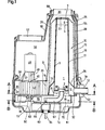
- a combustion chamber 1 is not described in detail ner burner 2.
- a flame tube 3 is placed on this burner 2 with its push-on end 8.
- This flame tube extends upwards in the interior of a heat exchanger 10, where it ends with its upper outlet opening 5 shortly before a ceiling surface 23 of the heat exchanger.
- a protective plate 7 is placed on the flame tube, which protects the heat exchanger top surface 23 from overheating.
- the heat exchanger 10 expediently a shaped piece made of an aluminum alloy, forms an annular space 11 at its open end through a base cylinder 13.
- a base collar 14 is also designed to hold the heat exchanger on a base plate 32.
- An exhaust pipe 12 leads from the annular space 11 for the extraction of the combustion gases to the outside.
- the heat exchanger is formed, for example, by a wave jacket 15. This consists of waves running evenly around the circumference with outer wave crests 18 and inner wave troughs 17. In the channels formed by these waves, the combustion gases flow after exiting the flame tube and deflecting downward at the ceiling surface 23, where they are received by the annular space 11 and finally be discharged outside through the exhaust pipe 12.
- the inner shaft channels are closed at the top by deflecting walls 25, which slope downwards towards the outside and thereby form favorable deflecting surfaces for the combustion gases.
- the annular space 11 formed by the base cylinder 13 is delimited on the outside by the transition walls 26.
- the flame tube lies directly against the inner surfaces of the wave troughs 17, the heat is transferred directly from the flame tube to the heat exchanger.
- the flame tube 3 adjacent to the wave troughs 17 closes off these wave channels, so that the combustion gases are divided into a large number of individual streams, which fall down in the form of relatively narrow flow layers and are surrounded by relatively large heating surfaces are. This results in a very even distribution of the combustion gases and thus also a uniform heat emission over the entire circumference of the heat exchanger.
- the annular space 11 acts here as a collecting space for the falling combustion gases and thus ensures their undisturbed extraction, even if there is only one exhaust port at one point.
- the heat exchanger 10 is surrounded by a heating space jacket 28 at a predetermined distance.
- a hot air inlet opening 29 at the level of the annular space 11 enables sufficient air access, a slight expansion 31 of the heating space jacket in the lower area ensuring a uniform distribution of the incoming air around the heat exchanger.
- the heating room is above the heat exchanger. brought together to form a hot air outlet opening 30, from which the hot air can either flow directly into the space to be heated or flow into a line system.
- the heat exchanger and thus the boiler room jacket can also be exactly cylindrical.
- a predetermined conicity which takes into account the gas concentration due to cooling and thereby avoids a flow delay, is advantageous.
- a forced flow is provided in order to improve and, in particular, to intensify the hot air flow between the heat exchanger and the heating space jacket 28 even in a narrow boiler room.
- a blower chamber 35 adjoins the hot air inlet opening 29, which is separated from an end plate 36 at the bottom Is delimited by a spiral chamber wall 37 and at the top by a cover plate 38.
- a suction opening 40 is formed in the cover plate, through which hot air flows into the blower chamber, compressed by a radial fan 42, for example in the form of a roller wheel, and through which Entry opening 29 into the boiler room ge is pressed.
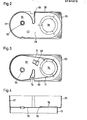
- the blower chamber as shown in FIG.
- the chamber wall forms a blower diffuser 43 which directly into the also moves to the side shifted inlet opening 29.
- the chamber wall forms a constriction 45, which delimits the inlet opening 29 on the inside, so that the hot air is fed radially to the heating space and in this way an approximately helically rising hot air flow, which is evenly distributed over the entire circumference of the heater, is initiated becomes.
- the fan 42 is driven by a motor 48 flanged onto the cover plate 38 by means of a stator 47 via the shaft 49, which is mounted in a bearing 50 on the other fan side.
- the end plate 36 is expediently an extension of the base plate 32, which securely closes off the heater and thus the combustion gas flow from the hot air.
- the air to be heated is removed from the room without special guidance and fed to the boiler room by the fan.
- an outer jacket 55 is provided, which surrounds the heating chamber jacket at a distance and extends on the side of the inlet opening 29 by a suction plenum chamber 56 which has an upwardly directed inlet opening 57, so that the ambient air both through this opening and through an annular inlet 58 which surrounds the hot air outlet opening 30 of the boiler room, can flow.
- the outer jacket expediently consists of two longitudinally divided shells.
- the outer jacket 55 continues to below the end plate and base plate 36 and forms a lower, self-contained fresh air chamber 61 with its attachment housing 60.
- its inlet 62 is at the Relocated the exhaust port 12, which surrounds it in a ring, so that the fresh air to be supplied to the burner is already preheated by the exhaust port. It also makes it possible to connect this heater to a wall connection box with a combined fresh air and exhaust gas opening (not shown). The preheating of the fresh air naturally also cools the combustion gas flowing out through the exhaust pipe 12.
- the coaxial fresh air supply has the further advantage that if there is a leak in the exhaust gas duct, the escaping gas is taken up by the fresh air stream and led to the burner, which automatically goes out if the enrichment is too strong. In this way, the interior of the room is reliably protected, especially with a longer exhaust pipe up to the outside wall.
- This fresh air chamber can also accommodate regulating devices, such as an automatically controlled gas valve 63, which is connected to a gas nozzle 65 fed by a gas line 64.
- This gas nozzle is located in an inlet opening of a mixer tube 67 which, held by a clamp 68 (FIG. 3), leads to the burner 2 and is formed by a flexible tube, the corrugated inner surface of which promotes the mixing of the gas with the first air.
- the fresh air also cools the gas valve and other fittings housed here.
- a forced guidance of the fresh air is also provided in this area.
- a prechamber 70 is formed in the interior of the fresh air chamber, which is delimited at the top by the end and base plates 36, 32, laterally by a wall 71 and below by a base plate 72.
- An inflow opening 73 is formed away from the inlet 62 and approximately coaxially to the suction opening 40 in the end plate. The fresh air entering through the inlet must therefore flow through the fresh air chamber 61 to the other end before it reaches the antechamber 70.
- This flow is supported by a fan wheel 75 aligned in the antechamber to the inflow opening 73, which conveys the sucked-in air past the gas nozzle as first air into the mixer pipe 67 and past it as second air through a base plate opening 76 to the burner 2.
- the fan wheel is arranged coaxially with the radial fan 42 and can also be driven by the motor 48.
- the prechamber wall 71 in the area of the fan wheel is again formed spirally with respect to the axle bearing 50, this pressure space designed in this way being supplemented by an insert wedge 74 (FIG. 3).
- blower chamber 42 and the pre-chamber 70 are separated by the common end and base plates 36, 32 and since the design of these chambers largely coincides, the design of such a molded piece can result in a significant simplification in device construction and assembly .
- 4, consists of the end plate and base plate 36, 32, the blower chamber wall 37 projecting therefrom on one side, which is expanded by a heating chamber base 78, and the prechamber wall 71 projecting on the other side.
- the invention is not restricted to the exemplary embodiment shown.
- the fresh air chamber and possibly also the antechamber are not absolutely necessary if the device is installed in a room floor in such a way that the fresh air is supplied exclusively from below this room floor.
- the formation of the fresh air and pre-chamber 61, 70 is also possible without the outer jacket 55.
- the heater offers the highest performance and greatest advantages with an outer jacket for circulating air or hot air, as well as with fresh air and antechamber, whereby these devices are expediently formed by a housing, thus creating a relatively small, compact heater that can be installed in the room .
Landscapes
- Engineering & Computer Science (AREA)
- Physics & Mathematics (AREA)
- Thermal Sciences (AREA)
- Mechanical Engineering (AREA)
- Chemical & Material Sciences (AREA)
- Combustion & Propulsion (AREA)
- General Engineering & Computer Science (AREA)
- Air-Conditioning For Vehicles (AREA)
Applications Claiming Priority (2)
| Application Number | Priority Date | Filing Date | Title |
|---|---|---|---|
| DE3325344 | 1983-07-13 | ||
| DE19833325344 DE3325344C2 (de) | 1983-07-13 | 1983-07-13 | Raumheizgerät für Kleinräume |
Publications (3)
| Publication Number | Publication Date |
|---|---|
| EP0131872A2 true EP0131872A2 (fr) | 1985-01-23 |
| EP0131872A3 EP0131872A3 (en) | 1986-01-08 |
| EP0131872B1 EP0131872B1 (fr) | 1987-09-30 |
Family
ID=6203927
Family Applications (1)
| Application Number | Title | Priority Date | Filing Date |
|---|---|---|---|
| EP19840107932 Expired EP0131872B1 (fr) | 1983-07-13 | 1984-07-06 | Chaudière pour petites enceintes |
Country Status (2)
| Country | Link |
|---|---|
| EP (1) | EP0131872B1 (fr) |
| DE (1) | DE3325344C2 (fr) |
Cited By (2)
| Publication number | Priority date | Publication date | Assignee | Title |
|---|---|---|---|---|
| EP0271783A3 (en) * | 1986-12-19 | 1988-09-21 | Philipp Kreis Gmbh & Co. Truma-Geratebau | Heater for small spaces, especially for mobile spaces |
| US11046150B2 (en) * | 2017-08-21 | 2021-06-29 | Eberspächer Climate Control Systems GmbH | Vehicle heater |
Families Citing this family (4)
| Publication number | Priority date | Publication date | Assignee | Title |
|---|---|---|---|---|
| AU201712794S (en) | 2016-11-23 | 2017-05-23 | Dometic Sweden Ab | Ventilation and air conditioning apparatus |
| DE112018005883B4 (de) | 2017-11-16 | 2025-12-18 | Dometic Sweden Ab | Klimatisierungsvorrichtung für Wohnmobile, Wohnmobil und Verfahren zur Zufuhr von klimatisierter Luft in einem Wohnmobil |
| USD905217S1 (en) | 2018-09-05 | 2020-12-15 | Dometic Sweden Ab | Air conditioning apparatus |
| IT201900019193A1 (it) | 2019-10-17 | 2021-04-17 | Dometic Sweden Ab | Apparato di condizionamento dell'aria per veicoli ricreativi |
Family Cites Families (6)
| Publication number | Priority date | Publication date | Assignee | Title |
|---|---|---|---|---|
| NL43876C (fr) * | 1928-01-25 | 1900-01-01 | ||
| US2384836A (en) * | 1941-02-26 | 1945-09-18 | Galvin Mfg Corp | Heater |
| GB876229A (en) * | 1960-03-09 | 1961-08-30 | Webasto Werk Baier Kg W | Improvements in and relating to heating devices operated with liquid fuel |
| US3265058A (en) * | 1964-01-24 | 1966-08-09 | Bahco Ab | Air heater using volatile fuels |
| DE2139504C3 (de) * | 1971-08-06 | 1979-06-28 | Fa. J. Eberspaecher, 7300 Esslingen | Heizgerät für mobile Einheiten |
| DE2434450C3 (de) * | 1974-07-17 | 1980-03-13 | Kreis, Philipp, 8000 Muenchen | Raumheizgerät, insbesondere für fahrbare Räume |
-
1983
- 1983-07-13 DE DE19833325344 patent/DE3325344C2/de not_active Expired
-
1984
- 1984-07-06 EP EP19840107932 patent/EP0131872B1/fr not_active Expired
Cited By (2)
| Publication number | Priority date | Publication date | Assignee | Title |
|---|---|---|---|---|
| EP0271783A3 (en) * | 1986-12-19 | 1988-09-21 | Philipp Kreis Gmbh & Co. Truma-Geratebau | Heater for small spaces, especially for mobile spaces |
| US11046150B2 (en) * | 2017-08-21 | 2021-06-29 | Eberspächer Climate Control Systems GmbH | Vehicle heater |
Also Published As
| Publication number | Publication date |
|---|---|
| EP0131872B1 (fr) | 1987-09-30 |
| EP0131872A3 (en) | 1986-01-08 |
| DE3325344A1 (de) | 1985-01-24 |
| DE3325344C2 (de) | 1986-11-13 |
Similar Documents
| Publication | Publication Date | Title |
|---|---|---|
| DE1476743A1 (de) | Gehaeuse fuer eine Gasturbine und einen elektrischen Generatorsatz | |
| EP0544853B1 (fr) | Appareil de chauffage d'air | |
| CH633347A5 (de) | Gasturbine. | |
| DE1451413A1 (de) | Tragbarer Raumheizapparat | |
| EP3428533B1 (fr) | Dispositif de gaz d'échappement pour une installation de combustion dans un véhicule | |
| EP0131872A2 (fr) | Chaudière pour petites enceintes | |
| DE68922313T2 (de) | Verbrennungsvorrichtung. | |
| EP0128463B1 (fr) | Appareil de chauffage des locaux pour des locaux de petite dimension | |
| DE2432850A1 (de) | Heizgeraet fuer fahrzeuge | |
| EP0348646B1 (fr) | Brûleur | |
| EP0281506A2 (fr) | Installation de chauffage avec préchauffage de l'air de combustion | |
| DE2609987A1 (de) | Brenner fuer kessel mit hohem widerstand | |
| DE2212320A1 (de) | Heizvorrichtung fuer Absorptionskuehler | |
| EP0271783B1 (fr) | Appareil de chauffage pour des petites enceintes, en particulier pour des enceintes amovibles | |
| EP1970233B1 (fr) | Dispositif de conditionnement d'air entrant dans un espace intérieur de véhicule | |
| DE2811586A1 (de) | Heizanlage | |
| DE1806519A1 (de) | Verfahren und Vorrichtung zum Aufheizen von Gasen,insbesondere Luft | |
| DE1558557C3 (de) | Umwälzbackofen | |
| DE3502648A1 (de) | Vorrichtung zur mischung eines haupt-gasstroms mit mindestens einem neben-gasstrom | |
| DE19538701C2 (de) | Warmlufterzeuger | |
| DE735331C (de) | Einrichtung zum Zufuehren von Zweitluft bei Kohlenstaubbrennern | |
| DE4109576A1 (de) | An der wand montierbarer, gegenueber dem raum abgeschlossener gasheizkessel mit geblaese | |
| EP0916907B1 (fr) | Soufflante mobile d'air chaud | |
| AT229998B (de) | Ölbrenneraggregat | |
| AT255012B (de) | Ölbrenneraggregat mit Niederdruckzerstäubung |
Legal Events
| Date | Code | Title | Description |
|---|---|---|---|
| PUAI | Public reference made under article 153(3) epc to a published international application that has entered the european phase |
Free format text: ORIGINAL CODE: 0009012 |
|
| AK | Designated contracting states |
Designated state(s): BE FR GB IT NL SE |
|
| PUAL | Search report despatched |
Free format text: ORIGINAL CODE: 0009013 |
|
| AK | Designated contracting states |
Designated state(s): BE FR GB IT NL SE |
|
| 17P | Request for examination filed |
Effective date: 19851204 |
|
| 17Q | First examination report despatched |
Effective date: 19860520 |
|
| GRAA | (expected) grant |
Free format text: ORIGINAL CODE: 0009210 |
|
| AK | Designated contracting states |
Kind code of ref document: B1 Designated state(s): BE FR GB IT NL SE |
|
| ITF | It: translation for a ep patent filed | ||
| ET | Fr: translation filed | ||
| GBT | Gb: translation of ep patent filed (gb section 77(6)(a)/1977) | ||
| PLBE | No opposition filed within time limit |
Free format text: ORIGINAL CODE: 0009261 |
|
| STAA | Information on the status of an ep patent application or granted ep patent |
Free format text: STATUS: NO OPPOSITION FILED WITHIN TIME LIMIT |
|
| 26N | No opposition filed | ||
| ITTA | It: last paid annual fee | ||
| PGFP | Annual fee paid to national office [announced via postgrant information from national office to epo] |
Ref country code: GB Payment date: 19930701 Year of fee payment: 10 |
|
| PGFP | Annual fee paid to national office [announced via postgrant information from national office to epo] |
Ref country code: SE Payment date: 19930728 Year of fee payment: 10 Ref country code: FR Payment date: 19930728 Year of fee payment: 10 |
|
| PGFP | Annual fee paid to national office [announced via postgrant information from national office to epo] |
Ref country code: NL Payment date: 19930731 Year of fee payment: 10 |
|
| PGFP | Annual fee paid to national office [announced via postgrant information from national office to epo] |
Ref country code: BE Payment date: 19930805 Year of fee payment: 10 |
|
| PG25 | Lapsed in a contracting state [announced via postgrant information from national office to epo] |
Ref country code: GB Effective date: 19940706 |
|
| PG25 | Lapsed in a contracting state [announced via postgrant information from national office to epo] |
Ref country code: SE Effective date: 19940707 |
|
| PG25 | Lapsed in a contracting state [announced via postgrant information from national office to epo] |
Ref country code: BE Effective date: 19940731 |
|
| BERE | Be: lapsed |
Owner name: PHILIPP KREIS G.M.B.H. & CO. TRUMA-GERATEBAU Effective date: 19940731 |
|
| EUG | Se: european patent has lapsed |
Ref document number: 84107932.0 Effective date: 19950210 |
|
| PG25 | Lapsed in a contracting state [announced via postgrant information from national office to epo] |
Ref country code: NL Effective date: 19950201 |
|
| GBPC | Gb: european patent ceased through non-payment of renewal fee |
Effective date: 19940706 |
|
| NLV4 | Nl: lapsed or anulled due to non-payment of the annual fee | ||
| PG25 | Lapsed in a contracting state [announced via postgrant information from national office to epo] |
Ref country code: FR Effective date: 19950331 |
|
| EUG | Se: european patent has lapsed |
Ref document number: 84107932.0 |
|
| REG | Reference to a national code |
Ref country code: FR Ref legal event code: ST |