EP0131916A2 - Outil pour la fabrication d'une connexion enfichable entre un tube en matière synthétique et un boîtier en matière synthétique pour dispositifs de jonction électrique - Google Patents
Outil pour la fabrication d'une connexion enfichable entre un tube en matière synthétique et un boîtier en matière synthétique pour dispositifs de jonction électrique Download PDFInfo
- Publication number
- EP0131916A2 EP0131916A2 EP84108197A EP84108197A EP0131916A2 EP 0131916 A2 EP0131916 A2 EP 0131916A2 EP 84108197 A EP84108197 A EP 84108197A EP 84108197 A EP84108197 A EP 84108197A EP 0131916 A2 EP0131916 A2 EP 0131916A2
- Authority
- EP
- European Patent Office
- Prior art keywords
- handle
- tube
- tool
- cutting
- hollow cylinder
- Prior art date
- Legal status (The legal status is an assumption and is not a legal conclusion. Google has not performed a legal analysis and makes no representation as to the accuracy of the status listed.)
- Withdrawn
Links
Images
Classifications
-
- B—PERFORMING OPERATIONS; TRANSPORTING
- B23—MACHINE TOOLS; METAL-WORKING NOT OTHERWISE PROVIDED FOR
- B23B—TURNING; BORING
- B23B5/00—Turning-machines or devices specially adapted for particular work; Accessories specially adapted therefor
- B23B5/16—Turning-machines or devices specially adapted for particular work; Accessories specially adapted therefor for bevelling, chamfering, or deburring the ends of bars or tubes
- B23B5/167—Tools for chamfering the ends of bars or tubes
-
- B—PERFORMING OPERATIONS; TRANSPORTING
- B23—MACHINE TOOLS; METAL-WORKING NOT OTHERWISE PROVIDED FOR
- B23D—PLANING; SLOTTING; SHEARING; BROACHING; SAWING; FILING; SCRAPING; LIKE OPERATIONS FOR WORKING METAL BY REMOVING MATERIAL, NOT OTHERWISE PROVIDED FOR
- B23D21/00—Machines or devices for shearing or cutting tubes
- B23D21/06—Hand-operated tube-cutters
- B23D21/10—Hand-operated tube-cutters with other cutting blades or tools
-
- H—ELECTRICITY
- H02—GENERATION; CONVERSION OR DISTRIBUTION OF ELECTRIC POWER
- H02G—INSTALLATION OF ELECTRIC CABLES OR LINES, OR OF COMBINED OPTICAL AND ELECTRIC CABLES OR LINES
- H02G1/00—Methods or apparatus specially adapted for installing, maintaining, repairing or dismantling electric cables or lines
-
- Y—GENERAL TAGGING OF NEW TECHNOLOGICAL DEVELOPMENTS; GENERAL TAGGING OF CROSS-SECTIONAL TECHNOLOGIES SPANNING OVER SEVERAL SECTIONS OF THE IPC; TECHNICAL SUBJECTS COVERED BY FORMER USPC CROSS-REFERENCE ART COLLECTIONS [XRACs] AND DIGESTS
- Y10—TECHNICAL SUBJECTS COVERED BY FORMER USPC
- Y10T—TECHNICAL SUBJECTS COVERED BY FORMER US CLASSIFICATION
- Y10T408/00—Cutting by use of rotating axially moving tool
- Y10T408/31—Convertible cutting means
-
- Y—GENERAL TAGGING OF NEW TECHNOLOGICAL DEVELOPMENTS; GENERAL TAGGING OF CROSS-SECTIONAL TECHNOLOGIES SPANNING OVER SEVERAL SECTIONS OF THE IPC; TECHNICAL SUBJECTS COVERED BY FORMER USPC CROSS-REFERENCE ART COLLECTIONS [XRACs] AND DIGESTS
- Y10—TECHNICAL SUBJECTS COVERED BY FORMER USPC
- Y10T—TECHNICAL SUBJECTS COVERED BY FORMER US CLASSIFICATION
- Y10T408/00—Cutting by use of rotating axially moving tool
- Y10T408/50—Cutting by use of rotating axially moving tool with product handling or receiving means
- Y10T408/51—Ejector
Definitions
- the present invention relates to a tool for producing a plug connection between a plastic tube and a plastic housing for electrical connection means, with a cutting head which is intended to surround the tube shell and can be rotated relative to the tube, in the interior of which a first knife for chamfering the one surrounded by the cutting head Tube and a second knife distanced from the former for cutting a pine cone-shaped rib protrudes into the jacket of the tube, the cutting head being connected in a rotationally fixed manner to one end of a rod-shaped handle, which at its other end is used to produce the fitting bore in the wall of the housing serving drill head.
- the applicant has already disclosed a tool of the aforementioned type with which a chamfer is attached to the pipe end and a pine cone-shaped rib is cut into the pipe jacket at a distance from the pipe end, such that the rib is partially pulled out of the pipe when it is cut into the inlet box Installed bore hole inserted pipe end on the wall of the inlet box and acts as a stop. It is then no longer possible for the end of the E in convenientlyen concrete or through the cable collection tube loaded from the intake box can move out because the pine cone shaped rib forms an effective stop. The interaction of the fitting bore, tube and rib also results in a sufficiently tight seal against the ingress of moisture into the inlet box. The chamfer at the end of the pipe makes it easier to push the pipe into the fitting bore.
- the problem with such a tool is the drill head for producing the fitting bore in the plastic housing, which in addition to the aforementioned inlet box can also be any other box for electrical installations.
- the drill head for producing the fitting bore in the plastic housing which in addition to the aforementioned inlet box can also be any other box for electrical installations.
- the drilling head comprises a cutting edge formed on one end face of a hollow steel cylinder, the other end of the hollow cylinder being fixedly connected to the handle and projecting from the relevant end face thereof and wherein within the hollow cylinder and A protective and centering plunger which can be displaced against the action of a spring extends centrally in the handle and forms a pressure plate at its free end which, in the normal state of the tool, projects beyond the cutting edge on the hollow cylinder.
- the tool can now be placed very precisely at the desired location by means of the pressure plate and the cutting edge can be effective relatively gently and without hooking on the housing wall.
- Ergonomic handling of the tool also results when the handle has an oval or elliptical cross-section for the drill head on the handle side and is of a smaller and at least approximately round cross-section for the cutting head, with the transition areas from the smaller handle circumference to the larger handle circumference stop surfaces for which form the hand enclosing the smaller grip circumference.
- this allows a high torque to be transferred to the drilling head without slipping, and on the other hand, it enables a high axial pressure of the cutting head against the pipe.
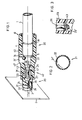
- the tool according to the invention for producing a plug connection between a plastic tube 1 and a plastic housing 2 for electrical connection means comprises in a known manner a drill head 20 for producing a fitting bore 3 in the wall of the housing 2 and a cutting head 30 for simultaneous production a chamfer 5 and for cutting the pine cone-like rib 4 on the tube 1.
- the drilling head 20 and the cutting head 30 are each fixed in the manner described in more detail below to one end of a rod-shaped handle 40, which is made of a suitable material, for example plastic.
- this rod-shaped handle is ergonomically designed according to the invention so that it has an approximately oval shape in cross section on the handle side 41 for the drill head 20, which allows high torque to be transmitted to the drill head 20 without slipping with the comprehensive hand.
- the handle 40 is of smaller and round cross-section, the transition regions 42 ′ towards the handle side 41 forming a stop for the comprehensive hand, which is what allows to exert a high axial pressure in the direction of the pipe 1 to be chamfered in order to hold the pipe 1 at the inner stop 33 of the cutting head 30.
- the cutting head 30 here comprises a central bore 31 of approximately the usual tube diameter, which ends at an annular shoulder that forms the abovementioned stop 33.
- a first knife 34 extends radially inwards, the cutting edge of which is designed such that the chamfer 5 is cut to a relative rotation between the pipe 1 and the cutting head 30 at the pipe end.
- the cutting edge of this knife can, however, also be such that it simultaneously causes a face rotation of the pipe end and possibly also an internal chamfering or deburring of the pipe.
- the resulting material chip falls into a chip receiving space 35 inside the cutting head 30 and can leave it through an opening 35 'in the handle 40.
- a second knife 36 extends radially inwards, which serves to cut the tubular jacket to form the pine cone-shaped rib 4.
- this knife is designed like a sickle in such a way that the material of the tube 1 that bulges out when the rib is cut can move into a recess in the knife 36.
- the tube 1 cut to a predetermined length is pushed into the cutting head 30 with its end, the protruding knife 34, which is relatively narrow in the radial direction, practically representing no resistance and at most one negligible indentation of a groove in the pipe jacket.
- the protruding knife 34 which is relatively narrow in the radial direction, practically representing no resistance and at most one negligible indentation of a groove in the pipe jacket.
- the drilling head 20 now comprises one on the one end face of a hollow cylinder 21 made of a suitable steel in a suitably ground cutting edge 22.
- the diameter of this cutting edge 22 or of the hollow cylinder 21 naturally corresponds practically to the diameter of the tube 1. It can be seen from the drawing that this hollow cylinder 21 protrudes from the relevant end face of the handle 40 and in the handle is firmly anchored in an annular groove 23. Locking screws (not shown in detail) can allow the hollow cylinder 21 to be replaced.
- the free lateral surface of the hollow cylinder 21 is expediently provided with suitable relaxation slots 24.
- a protective and centering plunger 26 is now supported in a guide bore 47 in the handle 40 within the hollow cylinder 21 and axially displaceably in the handle 40 against the action of a spring 25.
- this plunger 26 has a pressure plate 28 which, in the normal state of the tool, projects beyond the cutting edge 22 of the hollow cylinder 21, that is to say protrudes from the latter, and thus prevents an injury to the cutting edge 22.
- the diameter of this pressure plate 28 corresponds approximately to the inner diameter of the hollow cylinder 21.
- the outer end position of the pressure plate 28 is limited by an inner end flange 29 on the tappet 26, which cooperates with an inner annular shoulder 43 in the guide bore 47 of the handle 40.
- One end of the spring 25, which pushes the plunger 26 outwards, is supported on this annular shoulder 43, the other end of which cooperates with an annular shoulder 27 on the plunger 26.
- the tool is first placed on the wall of the housing 2 with the pressure plate 28 of the plunger 26 in order to produce the fitting bore 3 in the housing 2, in order then to exert an axial pressure on the handle 40 with simultaneous rotation, whereby there is an axial relative displacement between the pressure plate 28 and the hollow cylinder 21 and the cutting edge 22 becomes effective relatively gently and without hooking on the housing wall.
- the tool can be placed very precisely at the desired location through the pressure plate 28.
- the pressure plate 28 can also be provided with a small centering tip (not shown) which could be placed in a grain recess.
- the hollow cylinder 21 made of steel can be rolled and the jacket can then butt against one another along a longitudinal jacket seam.
- the two adjacent longitudinal edges can be radially offset from one another, if necessary, conical, which results in a cut edge 21 'which permits tolerance-compensating re-cutting.
- the assembly of the plunger 26 can be considerably simplified if, according to FIG. 3, the inner end flange 29 is designed as a slotted, resilient head 29 '.
- a tool for producing a plug connection between a plastic tube and a plastic housing for electrical connection means with excellent handling results from the above, taking into account the necessary safety precautions.
Landscapes
- Engineering & Computer Science (AREA)
- Mechanical Engineering (AREA)
- Drilling Tools (AREA)
- Shearing Machines (AREA)
- Packaging Of Annular Or Rod-Shaped Articles, Wearing Apparel, Cassettes, Or The Like (AREA)
Applications Claiming Priority (2)
| Application Number | Priority Date | Filing Date | Title |
|---|---|---|---|
| CH3833/83A CH659922A5 (de) | 1983-07-13 | 1983-07-13 | Werkzeug zur herstellung einer steckverbindung zwischen einem kunststoff-rohr und einem kunststoff-gehaeuse fuer elektrische anschlussmittel. |
| CH3833/83 | 1983-07-13 |
Publications (2)
| Publication Number | Publication Date |
|---|---|
| EP0131916A2 true EP0131916A2 (fr) | 1985-01-23 |
| EP0131916A3 EP0131916A3 (fr) | 1987-12-23 |
Family
ID=4264447
Family Applications (1)
| Application Number | Title | Priority Date | Filing Date |
|---|---|---|---|
| EP84108197A Withdrawn EP0131916A3 (fr) | 1983-07-13 | 1984-07-12 | Outil pour la fabrication d'une connexion enfichable entre un tube en matière synthétique et un boítier en matière synthétique pour dispositifs de jonction électrique |
Country Status (3)
| Country | Link |
|---|---|
| US (1) | US4583256A (fr) |
| EP (1) | EP0131916A3 (fr) |
| CH (1) | CH659922A5 (fr) |
Families Citing this family (3)
| Publication number | Priority date | Publication date | Assignee | Title |
|---|---|---|---|---|
| GB0005782D0 (en) * | 2000-03-11 | 2000-05-03 | Imi Yorkshire Fittings | Tube preparation device |
| US20100310332A1 (en) * | 2009-06-09 | 2010-12-09 | Henry Serba | Quick core removal hole cutting product |
| US20110010933A1 (en) * | 2009-07-20 | 2011-01-20 | Sam Van Duyne | Multi-functional tool and method of using same |
Family Cites Families (6)
| Publication number | Priority date | Publication date | Assignee | Title |
|---|---|---|---|---|
| GB596520A (en) * | 1945-07-28 | 1948-01-06 | Elsie Righton | An ejector corer |
| US983810A (en) * | 1910-05-05 | 1911-02-07 | Thomas Linsey Crossley | Circular core and disk cutting tool. |
| US1234468A (en) * | 1916-03-17 | 1917-07-24 | Mengel Box Company | Woodworking-tool. |
| US1234467A (en) * | 1916-03-17 | 1917-07-24 | Mengel Box Company | Woodworking-tool or barrel-saw. |
| US4274770A (en) * | 1979-11-09 | 1981-06-23 | Karl Singer | Hand-held burr remover for conduit and pipe |
| SE417018B (sv) * | 1979-12-20 | 1981-02-16 | Bengt Wester | Anordning for att i byggnader lokalisera den exakta placeringen av dolda objekt |
-
1983
- 1983-07-13 CH CH3833/83A patent/CH659922A5/de not_active IP Right Cessation
-
1984
- 1984-07-05 US US06/627,803 patent/US4583256A/en not_active Expired - Fee Related
- 1984-07-12 EP EP84108197A patent/EP0131916A3/fr not_active Withdrawn
Also Published As
| Publication number | Publication date |
|---|---|
| CH659922A5 (de) | 1987-02-27 |
| US4583256A (en) | 1986-04-22 |
| EP0131916A3 (fr) | 1987-12-23 |
Similar Documents
| Publication | Publication Date | Title |
|---|---|---|
| DE3035867C2 (fr) | ||
| DE1475216C3 (de) | Blindschraubverbindung | |
| EP0118778B1 (fr) | Clou d'ancrage | |
| DE3833040C2 (fr) | ||
| DD139779A5 (de) | Kabeldurchfuehrung mit zugentlastung | |
| EP0354446B1 (fr) | Elément de fixation avec taraudage interne | |
| DE2552254A1 (de) | Schlitz-spannschraube | |
| EP1746244A2 (fr) | Dispositif de fermeture pour ouvertures dans les bâtiments | |
| EP0131916A2 (fr) | Outil pour la fabrication d'une connexion enfichable entre un tube en matière synthétique et un boîtier en matière synthétique pour dispositifs de jonction électrique | |
| WO2008058621A1 (fr) | Cheville à expansion avec manchon flexible en direction axiale | |
| DE19822915C1 (de) | Vorrichtung zum Verbinden von Fluidleitungen | |
| DE59703501C5 (de) | Spreizdübel | |
| DE3424075C2 (de) | Steckverbinder | |
| DE102016123316B4 (de) | Werkzeug zum Schneiden eines Gewindes | |
| DE3206678A1 (de) | Bohrwerkzeug zum erzeugen eines hinterschnittes in einer vorgebohrten zylindrischen bohrung | |
| DE9419900U1 (de) | Osteosynthesevorrichtung | |
| EP2612040B1 (fr) | Cheville à expansion | |
| EP0290654A1 (fr) | Cheville à expansion pour l'ancrage à engagement positif dans un trou de forage | |
| CH647842A5 (de) | Bohrwerkzeug zum herstellen einer radialen erweiterung in einer zylindrischen grundbohrung. | |
| DE3108016A1 (de) | Duebel | |
| EP2128948B1 (fr) | Elément d'installation | |
| DE2428280C3 (de) | Werkzeug zur Herstellung einer Steckverbindung zwischen einem Kunststoffrohr und einem Unterputz-Einlasskasten | |
| DE4428570C1 (de) | Rohrkupplung | |
| DE1684261A1 (de) | Vorrichtung zum Aufbau von Betonschalungen od. dgl. | |
| DE3806971A1 (de) | Einrichtung zum einsetzen eines rohrartigen elementes in eine rohrleitung |
Legal Events
| Date | Code | Title | Description |
|---|---|---|---|
| PUAI | Public reference made under article 153(3) epc to a published international application that has entered the european phase |
Free format text: ORIGINAL CODE: 0009012 |
|
| 17P | Request for examination filed |
Effective date: 19840712 |
|
| AK | Designated contracting states |
Designated state(s): AT DE FR GB IT |
|
| PUAL | Search report despatched |
Free format text: ORIGINAL CODE: 0009013 |
|
| AK | Designated contracting states |
Kind code of ref document: A3 Designated state(s): AT DE FR GB IT |
|
| STAA | Information on the status of an ep patent application or granted ep patent |
Free format text: STATUS: THE APPLICATION HAS BEEN WITHDRAWN |
|
| 18W | Application withdrawn |
Withdrawal date: 19880513 |
|
| RIN1 | Information on inventor provided before grant (corrected) |
Inventor name: REICHLE, HANS |