EP0131941A2 - Dispositif d'arrêt pour portes à rouleau, grilles à rouleau ou actionnements enrouleurs semblables - Google Patents
Dispositif d'arrêt pour portes à rouleau, grilles à rouleau ou actionnements enrouleurs semblables Download PDFInfo
- Publication number
- EP0131941A2 EP0131941A2 EP84108297A EP84108297A EP0131941A2 EP 0131941 A2 EP0131941 A2 EP 0131941A2 EP 84108297 A EP84108297 A EP 84108297A EP 84108297 A EP84108297 A EP 84108297A EP 0131941 A2 EP0131941 A2 EP 0131941A2
- Authority
- EP
- European Patent Office
- Prior art keywords
- brake disc
- drive
- support element
- pawl
- der
- Prior art date
- Legal status (The legal status is an assumption and is not a legal conclusion. Google has not performed a legal analysis and makes no representation as to the accuracy of the status listed.)
- Granted
Links
Images


Classifications
-
- E—FIXED CONSTRUCTIONS
- E06—DOORS, WINDOWS, SHUTTERS, OR ROLLER BLINDS IN GENERAL; LADDERS
- E06B—FIXED OR MOVABLE CLOSURES FOR OPENINGS IN BUILDINGS, VEHICLES, FENCES OR LIKE ENCLOSURES IN GENERAL, e.g. DOORS, WINDOWS, BLINDS, GATES
- E06B9/00—Screening or protective devices for wall or similar openings, with or without operating or securing mechanisms; Closures of similar construction
- E06B9/56—Operating, guiding or securing devices or arrangements for roll-type closures; Spring drums; Tape drums; Counterweighting arrangements therefor
- E06B9/80—Safety measures against dropping or unauthorised opening; Braking or immobilising devices; Devices for limiting unrolling
- E06B9/82—Safety measures against dropping or unauthorised opening; Braking or immobilising devices; Devices for limiting unrolling automatic
- E06B9/84—Safety measures against dropping or unauthorised opening; Braking or immobilising devices; Devices for limiting unrolling automatic against dropping
Definitions
- the invention relates to a safety gear for roller shutters, rolling grilles or similar winding drives, in which a trigger is arranged on a hub rotating with a drive or deflecting shaft in such a way that when a permissible speed of the drive or deflecting shaft is exceeded, a trigger acting between it and a fixed point Latches locking device, and in which the locking device is equipped with a, preferably plastic, deformable energy absorber for damping and reshaping (destruction) the movement, in particular the fall energy, of the load.
- a generic safety device is known from German Patent 24 33 237.
- a disk brake is known from French patent specification 20 32 528, in which, as usual, there are two working positions of the brake pads opposite on the end faces of the brake disk. In the first working position, the brake disc runs freely and freely from the brake pads between them and has the usual smooth and undeformed disc shape. In the second working position, the opposing brake pads are pressed against the brake disc, so that the friction that takes effect gradually brings the brake disc to a standstill.
- the braking effect in this known disc brake is now increased by the fact that three brake pads are preferably offset from one another on a quarter-circular support element and are therefore able to deform the brake disc in a wavy, elastic manner on about a quarter of its circumference.
- the material of the brake disc must ensure that the brake disc takes on a completely flat disc shape again outside of its relatively short, wavy, deformed circumferential area, because otherwise no proper free running of the brake disc is guaranteed in the unbraked state; likewise the brake disc also take on a flat disc shape in the area of the brake shoes when the brake shoes are pulled back at the end of the braking process.
- the invention has for its object to provide a safety device of the type mentioned, in which the energy sensor can be used several times without having to be exchanged or edited.
- a safety device according to the invention should be fully functional even after years of non-use;
- the technical solution for this is a brake disk and deformation elements arranged on both sides of the brake disk on an annular support element, evenly distributed on the circumference of the brake disk and offset from one another, which are arranged in the axial direction in such a way that the brake disk is deformed in a circumferential undulating manner in any operating situation the support element rotates during normal movement of the winding drive with the brake disc, wherein either the brake disc is rotatably connected to the drive or deflection shaft and the support element can be fixed by the locking device or vice versa.
- the invention is therefore based on the basic idea of equipping the safety gear with an overload clutch, in the case of which a brake disk starts to move relative to the clutch disks and thereby from Verfor Mung elements is deformed all around wavy, so that the falling energy of the load acting on the safety gear is primarily converted into deformation energy of the brake disc, the rotation of the deformation shaft around the circumference of the brake disc leads to a damping effect, so that the locking device does not jerky, but with a time delay and dampens the falling load gradually, but brings it to a standstill.
- the carrier element consists of two ring disks arranged on both sides of the brake disc with e.g. Four deformation elements each, distributed uniformly on the circumference of the end face facing the brake disc.
- this purpose is also served by deformation elements which can be set to a predetermined degree of deformation and which, inter alia, allow the safety gear to be reset to the original braking force in the event of a brake disc becoming thinner due to wear.
- the deformation elements can be supported as simple projections of the support element, preferably at right angles, against the brake disc, so that when the safety gear triggers, approximately 10 to 15% of the braking energy is applied by sliding friction and the majority of the braking energy is applied by the brake disc deformation.
- the static friction of the deformation elements on the brake disc is greater than the sliding friction and, moreover, depends to a large extent on the surface properties of the brake disc and the deformation elements, it can be advantageous according to another development of the invention as a deform mung elements to use roles and to rotate them on the support element so that when the safety gear is triggered, the braking energy is only available in the form of deformation energy.
- the damping measure can be adjusted particularly precisely and remains essentially unchanged even after years of non-use of the safety gear.
- Brake discs made of stainless steel also serve this purpose, the material properties of which remain unchanged even without maintenance for the purpose required here.
- a very simple and effective practical embodiment of the invention results from the fact that the support element is non-rotatably, positively connected to a ratchet wheel of the locking device.
- the ratchet wheels with ratchets and a control disk with a feeler roller which have also been used up to now, can be used as a trigger and locking device.
- One or more ratchet wheels form a support element consisting of two ring disks and the control disk forms a unit which is firmly screwed together and rotates synchronously with one another.
- the pawl In order to prevent the pawl from disengaging again immediately after the safety catch has been triggered, for example by reversing the direction of rotation, the pawl is provided with a rocker arm mounted thereon which, when Locking the pawl in the ratchet wheel tilts into a position in which the moment generated by the rocker arm holds the pawl in the locked position. Accordingly, after the triggering event, the rocker arm itself must first be turned back to its normal position before a load can be raised or lowered again. This forces the user to interrupt his work and reminds him to first determine the cause of the safety gear tripping and to remedy any damage before lifting and lowering loads again.
- the safety device according to the invention has the advantage that, despite the simplest design, it can be reused several times without the energy absorber having to be replaced, serviced or otherwise processed.
- the invention makes it possible for the first time to check the functionality of the safety gear before starting up the system for lifting and lowering the loads and to adjust the desired braking force to the damping behavior; it is also possible to test the safety of the safety device in its simplest manner at any time intervals.
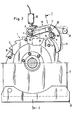
- a safety device 1 for lifting and lowering loads consists of a stationary support plate 2, a trigger consisting of a feeler roller 3 and a control disk 4, a locking device consisting of a ratchet wheel 5 and a ratchet 6 as well as a brake disk 7 and an annular support element 8 with deformation elements 9 existing energy absorbers.
- a key 12 On a drive or deflecting shaft 10 for lifting and lowering the load, a key 12 is connected in a rotationally fixed manner by means of a feather key 11, with which a package of one or more brake disks 7 arranged in parallel is screwed tight and which is lightweight relative to the support plate 2 by means of a ball bearing 13 is rotatably mounted.
- the support element 8 consists of two washers 14, 15 which are arranged on both sides of the brake disc 7 and are radially screwed together radially outside the same by means of bolts 16 with the control disc 4 in between.
- One or more pawl ratchet wheels 5, preferably stamped from sheet metal, are also screwed to the supporting element 8 in a rotationally fixed manner using the same screw bolts.
- This firmly screwed unit rotates synchronously during normal operation with the brake disc 7, because it is frictionally clamped to the support element 8 by the fact that the washers 14 and 15 on the end face to the brake disc 7 towards the circumference evenly distributed deformation elements 9, which are mutually attached to the two washers and the brake disc 7 under maintain such a high preload that the brake disc 7 is deformed at least elastically, but preferably even plastically, undulatingly over its circumference, as is shown in broken lines in FIG. 3.
- the deformation elements 9 can be rollers mounted in the ring disks in a roller cage.
- the pawl 6 and the feeler roller 3 are located at the ends of a lever 18 which can be pivoted slightly about its axis 17 and which is balanced in a known manner so that the feeler roller 3 rolls over its cam when the control disc 4 is not moving too quickly and only at high speeds of the cam can no longer follow and the pawl 7 with the ratchet wheel 5 engages. Since the ratchet wheel 5 initially rotates synchronously with the drive or deflection shaft 10 due to the pretension between the support element 8 and the brake disc 7, it exerts a large thrust on the pawl 6.
- This thrust can avoid the pawl 6 over the distance a, so that a stop 19 of the pawl 6 is supported on a bolt-shaped stationary counter bearing 20 and the thrust is only absorbed by this counter bearing 20 and no longer by the rolling bearing 21 with which the Lever 18 is rotatably mounted on a fixed shaft 23 via circlips 22.
- the axis 17 is located at the end of a lever 27 which can be pivoted about a fixed joint 26.
- the brake disc 7 must slide past the deformation elements 9, so that the wave-shaped deformation of the brake disc 7 propagates on its circumference. 3, the brake disc 7 is deformed, for example, in four approximately sinusoidal shafts, so that each revolution of the brake disc 7 is deformed four times to the right and to the left from the center plane when the brake disc rotates with the locking device fixed. The deformation energy required for this dampens the falling energy which is reduced by the braking effect.
- the wave formation of the brake disk 7 can be seen particularly clearly from FIGS. 4a and 4b, in FIG. 4a being made in one piece with the ring disks 14, 15, while in FIG. 4b the deformation elements 9 can be adjusted to a specific deformation level by means of adjusting screws 24 .
- the support plate 2 is mounted on a conventional bracket 25 fixed.
- An angled rocker arm with a relatively heavy lever arm 28 and a relatively light lever arm 29 is mounted on the axis 17 in such a way that the entire rocker arm weight is supported on the counter bearing 20 by a free movement of the load over the free end of the light lever arm 29.
- the free end of the light lever arm 29 is released after the pawl 6 has engaged, so that the rocker arm weight now resting on the pawl 6 holds the pawl in the latched position.
- an electrical switch 30 force disconnector
- an electrical switch 30 can be actuated, which opens two contacts when the pawl 6 engages in the ratchet wheel 5.
Landscapes
- Engineering & Computer Science (AREA)
- Structural Engineering (AREA)
- Architecture (AREA)
- Civil Engineering (AREA)
- Operating, Guiding And Securing Of Roll- Type Closing Members (AREA)
- Braking Arrangements (AREA)
- Refuge Islands, Traffic Blockers, Or Guard Fence (AREA)
- Machines For Manufacturing Corrugated Board In Mechanical Paper-Making Processes (AREA)
- Transmission Devices (AREA)
Priority Applications (1)
| Application Number | Priority Date | Filing Date | Title |
|---|---|---|---|
| AT84108297T ATE22960T1 (de) | 1983-07-16 | 1984-07-14 | Fangvorrichtung fuer rolltore, rollgitter oder aehnliche wickeltriebe. |
Applications Claiming Priority (2)
| Application Number | Priority Date | Filing Date | Title |
|---|---|---|---|
| DE3325750 | 1983-07-16 | ||
| DE3325750A DE3325750A1 (de) | 1983-07-16 | 1983-07-16 | Fangvorrichtung fuer heb- und senkbare lasten |
Publications (3)
| Publication Number | Publication Date |
|---|---|
| EP0131941A2 true EP0131941A2 (fr) | 1985-01-23 |
| EP0131941A3 EP0131941A3 (en) | 1985-10-02 |
| EP0131941B1 EP0131941B1 (fr) | 1986-10-15 |
Family
ID=6204182
Family Applications (1)
| Application Number | Title | Priority Date | Filing Date |
|---|---|---|---|
| EP84108297A Expired EP0131941B1 (fr) | 1983-07-16 | 1984-07-14 | Dispositif d'arrêt pour portes à rouleau, grilles à rouleau ou actionnements enrouleurs semblables |
Country Status (3)
| Country | Link |
|---|---|
| EP (1) | EP0131941B1 (fr) |
| AT (1) | ATE22960T1 (fr) |
| DE (2) | DE3325750A1 (fr) |
Cited By (1)
| Publication number | Priority date | Publication date | Assignee | Title |
|---|---|---|---|---|
| DE202007002787U1 (de) | 2007-02-22 | 2008-07-03 | GfA-Antriebstechnik Gesellschaft mit beschränkter Haftung | Fangvorrichtung zum Stillsetzen einer Umlenk- oder Wickelwelle |
Families Citing this family (4)
| Publication number | Priority date | Publication date | Assignee | Title |
|---|---|---|---|---|
| DE3802775C1 (en) * | 1988-01-30 | 1989-09-21 | Wilhelm 4420 Coesfeld De Uhlenkotte | Securing device for a winding shaft |
| DE3901206C2 (de) * | 1989-01-17 | 1994-11-10 | Mfz Antriebe Gmbh | Fangvorrichtung zur Sicherung von Rolltoren u.a. |
| DE4002074C1 (en) * | 1990-01-25 | 1991-05-08 | Gfa - Antriebstechnik Gmbh, 4000 Duesseldorf, De | Arrester for roller door, roller shutter etc. lifting drive - whose hub has two firmly coupled brake hubs with rotary cam disc in between |
| DE4407416C2 (de) * | 1994-03-05 | 1996-02-01 | Flender Himmelwerk Gmbh | Sicherungsvorrichtung gegen den Absturz von motorisch auf- und abbewegbaren Objekten |
Family Cites Families (4)
| Publication number | Priority date | Publication date | Assignee | Title |
|---|---|---|---|---|
| FR2032528A5 (fr) * | 1969-02-07 | 1970-11-27 | Lebour Arnaud | |
| DE2617784C3 (de) * | 1976-04-23 | 1979-09-13 | Elero Ag, Daellikon (Schweiz) | Abrollsicherung für eine antreibbare Wickeltrommel |
| DE8205731U1 (de) * | 1982-03-02 | 1982-07-29 | Fa. W.u.H. Neukirchen, 4060 Viersen | Fangvorrichtung fuer einen rolladen, ein rolltor od. dgl. |
| DE8320578U1 (de) * | 1983-07-16 | 1984-01-05 | GfA - Antriebstechnik GmbH, 4000 Düsseldorf | Fangvorrichtung fuer heb- und senkbare lasten |
-
1983
- 1983-07-16 DE DE3325750A patent/DE3325750A1/de not_active Withdrawn
-
1984
- 1984-07-14 EP EP84108297A patent/EP0131941B1/fr not_active Expired
- 1984-07-14 AT AT84108297T patent/ATE22960T1/de not_active IP Right Cessation
- 1984-07-14 DE DE8484108297T patent/DE3460997D1/de not_active Expired
Cited By (3)
| Publication number | Priority date | Publication date | Assignee | Title |
|---|---|---|---|---|
| DE202007002787U1 (de) | 2007-02-22 | 2008-07-03 | GfA-Antriebstechnik Gesellschaft mit beschränkter Haftung | Fangvorrichtung zum Stillsetzen einer Umlenk- oder Wickelwelle |
| DE102008010675A1 (de) | 2007-02-22 | 2008-09-04 | GfA-Antriebstechnik Gesellschaft mit beschränkter Haftung | Fangvorrichtung zum Stillsetzen einer Umlenk- oder Wickelwelle |
| DE102008010675B4 (de) * | 2007-02-22 | 2014-08-07 | Gesellschaft für Antriebstechnik Dr.Ing .Günther Hammann GmbH & Co. | Fangvorrichtung zum Stillsetzen einer Umlenk- oder Wickelwelle |
Also Published As
| Publication number | Publication date |
|---|---|
| DE3460997D1 (en) | 1986-11-20 |
| EP0131941A3 (en) | 1985-10-02 |
| DE3325750A1 (de) | 1985-01-24 |
| ATE22960T1 (de) | 1986-11-15 |
| EP0131941B1 (fr) | 1986-10-15 |
Similar Documents
| Publication | Publication Date | Title |
|---|---|---|
| DE69416720T2 (de) | Verfahren und Einrichtung zum Auslösen eines Aufzugssicherheitsmechanismus | |
| EP0149658B1 (fr) | Unite d'entrainement de galets | |
| DE69509265T2 (de) | Vorrichtung in einem Aufzugsübergeschwindigkeitsbegrenzer | |
| EP2422105B1 (fr) | Embrayage centrifuge et descendeur à entraînement direct | |
| DE3910369C2 (fr) | ||
| DE2528067C2 (de) | Geschwindigkeitsbegrenzer für Aufzüge | |
| DE102004023123A1 (de) | Absturzsicherung | |
| EP3883875A1 (fr) | Limiteur de vitesse pour un engin de levage comprenant un frein actionné par la force centrifuge | |
| DE69511589T2 (de) | Verfahren und Vorrichtung zum Auslösen eines Aufzugssicherheitsmechanismus | |
| EP0131941B1 (fr) | Dispositif d'arrêt pour portes à rouleau, grilles à rouleau ou actionnements enrouleurs semblables | |
| EP0275509A2 (fr) | Dispositif antichute avec anneau de blocage pour portes enroulables | |
| EP0114041B1 (fr) | Porte | |
| DE3330753C2 (de) | Bewegungsdämpfende Stützeinrichtung | |
| DE1800270A1 (de) | Geschwindigkeitsbegrenzer fuer Aufzuege | |
| DE8320578U1 (de) | Fangvorrichtung fuer heb- und senkbare lasten | |
| DE19734467B4 (de) | Fliehkraftgesteuerter Schaltautomat | |
| DE2617784C3 (de) | Abrollsicherung für eine antreibbare Wickeltrommel | |
| EP2331838B1 (fr) | Embrayage à friction avec protection contre les surcharges | |
| DE19805568B4 (de) | Fangvorrichtung für eine Wickelwelle | |
| DE2726154C2 (de) | Fangvorrichtung | |
| DE9204156U1 (de) | Stellantrieb für Lichtkuppeln o.dgl. | |
| DE2737433C2 (de) | Sicherheitsbremse für Aufzugkabinen od. dgl. Fördereinrichtungen | |
| EP0297289B1 (fr) | Accouplement de sécurité | |
| DE3622867C1 (en) | Anti-drop device for loads which can be drawn up using a winding shaft | |
| DE3048090C2 (fr) |
Legal Events
| Date | Code | Title | Description |
|---|---|---|---|
| PUAI | Public reference made under article 153(3) epc to a published international application that has entered the european phase |
Free format text: ORIGINAL CODE: 0009012 |
|
| AK | Designated contracting states |
Designated state(s): AT CH DE FR GB IT LI NL SE |
|
| PUAL | Search report despatched |
Free format text: ORIGINAL CODE: 0009013 |
|
| AK | Designated contracting states |
Designated state(s): AT CH DE FR GB IT LI NL SE |
|
| 17P | Request for examination filed |
Effective date: 19850813 |
|
| 17Q | First examination report despatched |
Effective date: 19860403 |
|
| GRAA | (expected) grant |
Free format text: ORIGINAL CODE: 0009210 |
|
| AK | Designated contracting states |
Kind code of ref document: B1 Designated state(s): AT CH DE FR GB IT LI NL SE |
|
| PG25 | Lapsed in a contracting state [announced via postgrant information from national office to epo] |
Ref country code: NL Effective date: 19861015 Ref country code: IT Free format text: LAPSE BECAUSE OF FAILURE TO SUBMIT A TRANSLATION OF THE DESCRIPTION OR TO PAY THE FEE WITHIN THE PRESCRIBED TIME-LIMIT;WARNING: LAPSES OF ITALIAN PATENTS WITH EFFECTIVE DATE BEFORE 2007 MAY HAVE OCCURRED AT ANY TIME BEFORE 2007. THE CORRECT EFFECTIVE DATE MAY BE DIFFERENT FROM THE ONE RECORDED. Effective date: 19861015 Ref country code: FR Free format text: THE PATENT HAS BEEN ANNULLED BY A DECISION OF A NATIONAL AUTHORITY Effective date: 19861015 |
|
| REF | Corresponds to: |
Ref document number: 22960 Country of ref document: AT Date of ref document: 19861115 Kind code of ref document: T |
|
| PG25 | Lapsed in a contracting state [announced via postgrant information from national office to epo] |
Ref country code: SE Effective date: 19861031 |
|
| REF | Corresponds to: |
Ref document number: 3460997 Country of ref document: DE Date of ref document: 19861120 |
|
| EN | Fr: translation not filed | ||
| NLV1 | Nl: lapsed or annulled due to failure to fulfill the requirements of art. 29p and 29m of the patents act | ||
| PG25 | Lapsed in a contracting state [announced via postgrant information from national office to epo] |
Ref country code: AT Effective date: 19870714 |
|
| PG25 | Lapsed in a contracting state [announced via postgrant information from national office to epo] |
Ref country code: LI Effective date: 19870731 Ref country code: CH Effective date: 19870731 |
|
| PLBE | No opposition filed within time limit |
Free format text: ORIGINAL CODE: 0009261 |
|
| STAA | Information on the status of an ep patent application or granted ep patent |
Free format text: STATUS: NO OPPOSITION FILED WITHIN TIME LIMIT |
|
| 26N | No opposition filed | ||
| REG | Reference to a national code |
Ref country code: CH Ref legal event code: PL |
|
| PG25 | Lapsed in a contracting state [announced via postgrant information from national office to epo] |
Ref country code: GB Effective date: 19880714 |
|
| GBPC | Gb: european patent ceased through non-payment of renewal fee | ||
| PGFP | Annual fee paid to national office [announced via postgrant information from national office to epo] |
Ref country code: DE Payment date: 19930910 Year of fee payment: 10 |
|
| PG25 | Lapsed in a contracting state [announced via postgrant information from national office to epo] |
Ref country code: DE Effective date: 19950401 |