EP0132056B1 - Rheometer und Verfahren zur Benutzung desselben - Google Patents
Rheometer und Verfahren zur Benutzung desselben Download PDFInfo
- Publication number
- EP0132056B1 EP0132056B1 EP84304169A EP84304169A EP0132056B1 EP 0132056 B1 EP0132056 B1 EP 0132056B1 EP 84304169 A EP84304169 A EP 84304169A EP 84304169 A EP84304169 A EP 84304169A EP 0132056 B1 EP0132056 B1 EP 0132056B1
- Authority
- EP
- European Patent Office
- Prior art keywords
- rotor
- sample
- rotated
- torque
- rheometer
- Prior art date
- Legal status (The legal status is an assumption and is not a legal conclusion. Google has not performed a legal analysis and makes no representation as to the accuracy of the status listed.)
- Expired
Links
- 238000000034 method Methods 0.000 title claims description 12
- 230000002441 reversible effect Effects 0.000 claims abstract description 45
- 238000011084 recovery Methods 0.000 claims abstract description 27
- 229920001971 elastomer Polymers 0.000 claims abstract description 10
- 229920003051 synthetic elastomer Polymers 0.000 claims abstract description 8
- 239000000463 material Substances 0.000 claims description 13
- 238000010008 shearing Methods 0.000 claims description 5
- 238000010276 construction Methods 0.000 claims description 4
- 239000000806 elastomer Substances 0.000 claims description 2
- 238000003780 insertion Methods 0.000 claims description 2
- 230000037431 insertion Effects 0.000 claims description 2
- 238000012360 testing method Methods 0.000 abstract description 15
- 241001441571 Hiodontidae Species 0.000 abstract description 3
- 238000005259 measurement Methods 0.000 description 6
- 230000010355 oscillation Effects 0.000 description 5
- 238000004073 vulcanization Methods 0.000 description 5
- 238000010438 heat treatment Methods 0.000 description 2
- 238000012986 modification Methods 0.000 description 2
- 230000004048 modification Effects 0.000 description 2
- 230000000704 physical effect Effects 0.000 description 2
- 230000000979 retarding effect Effects 0.000 description 2
- 230000009286 beneficial effect Effects 0.000 description 1
- 238000011161 development Methods 0.000 description 1
- 230000018109 developmental process Effects 0.000 description 1
- 230000002093 peripheral effect Effects 0.000 description 1
Images


Classifications
-
- G—PHYSICS
- G01—MEASURING; TESTING
- G01N—INVESTIGATING OR ANALYSING MATERIALS BY DETERMINING THEIR CHEMICAL OR PHYSICAL PROPERTIES
- G01N11/00—Investigating flow properties of materials, e.g. viscosity, plasticity; Analysing materials by determining flow properties
- G01N11/10—Investigating flow properties of materials, e.g. viscosity, plasticity; Analysing materials by determining flow properties by moving a body within the material
- G01N11/14—Investigating flow properties of materials, e.g. viscosity, plasticity; Analysing materials by determining flow properties by moving a body within the material by using rotary bodies, e.g. vane
Definitions
- This invention relates to rheometers, which are instruments for measuring physical properties of uncured or unvulcanised, or partly cured or partly vulcanised, rubber or synthetic elastomers.
- the invention is specifically concerned with rheometers which include a chamber in which, in use, a sample of the material of which the properties are to be measured is held under pressure, a rotor which has a surface in contact with the sample in the chamber and has a drive by which it is rotatable, and torque measuring means for measuring the torque applied to the rotor as it is rotated.
- the rotor may be a disc which is rotatably mounted in the chamber and, in use, is entirely surrounded by the sample of material, or it may alternatively form a part of the wall of the chamber, the remainder of the wall of which is stationary.
- Such rheometers are subsequently referred to as being of the type described.
- the rotor can be disconnected from its drive at any time during the measurement and the magnitude of the angular return movement of the rotor, which is brought about by the recovery of the material in the chamber, is then measured.
- the aim of the present invention is to enable more accurate and informative measurements of the recovery of samples of rubber or synthetic elastomers to be made during the course of vulcanisation or curing by means of a rheometer of the type described.
- a rheometer of the type described is characterised in that the drive is reversible and includes a pulse-operated electric stepping motor which is connected to the rotor through gearing, the drive enabling the rotor to be rotated selectively in either direction in steps of not more than 20 minutes of arc.
- the construction of the rotor drive in this way also gives rise to a new method of measuring the recovery of a sample of rubber or of a synthetic elastomer after it has been subjected to a substantial shearing strain using a rheometer in accordance with the invention just described.
- This method comprises inserting a sample of the elastomer under pressure into the chamber of the rheometer in accordance with the invention and rotating the rotor in one direction to apply a substantial shear strain to the sample, the angular strain being greater than the maximum angular recovery of the sample, and the method is characterised in that the rotation of the rotor in the one direction is then stopped; the rotor is rotated in a reverse direction step by step through predetermined angles; the torque applied to the rotor by the sample as it recovers after each step of reverse rotation is observed from the torque measuring means, and then the rotor is rotated through a further step until the observed torque falls to zero, at which time the reverse rotation of the rotor indicates the angular recovery of the sample.
- steps of 20 minutes of arc are the maximum through which the rotor can be rotated to provide a reading of the recovery of the sample of sufficient accuracy for practical purposes, but preferably the construction of the stepping motor and of the gearing through which the rotor is connected to the stepping motor are such that each step is smaller than this and, in one example, each step is 1.8 minutes of arc and in another example, where very great accuracy is necessary, each step of rotation is only through a few seconds of arc.
- the rheometer in accordance with the invention is preferably provided with a timing device which, in operation, indicates the time taken for variations in the torque on the rotor to take place after the rotor has been rotated by the drive.
- the timing device is preferably electrical and so also is the torque measuring means.
- the torque measuring means and the timing device are both connected to an electronic controller which indicates the required time intervals automatically.
- the same electronic controller preferably also includes pulse generating circuits for operating the electric stepping motor, or the motors if the drive includes more than one.
- the rotor is again rotated in a forward direction through one or more steps until a minimum observable torque in the reverse direction is indicated by the torque measuring means.
- This final very small forward rotation of the rotor takes up any lag that there may be in the reading of the torque measuring means and also any backlash that there may be in the driving mechanism. In this way a still more accurate measurement of the recovery of the sample may be obtained.
- the drive of the rotor may include only a single pulse-operated electric stepping motor which is reversible.
- the drive preferably incorporates means by which the rotor may be rotated step by step continuously in one direction or the other, or by which it may be oscillated by being rotated through one or more steps in one direction followed by rotation through one or more steps in an opposite direction.
- the drive preferably includes two pulse-operated electric stepping motors which are connected to the rotor through differential gearing.
- This drive is however even more advantageous if it is operated by changing the speeds of rotation of the two motors whilst continuing to rotate each motor continuously in one direction.
- rotation of one motor faster than the other motor rotates the rotor in one direction; rotation of the other motor faster than the one motor rotates the rotor in an opposite direction and alternate rotation of the two motors faster and slower than each other oscillates the rotor.
- Operation of the drive in this way has the advantage that it is never necessary to stop either of the motors to rotate the rotor in either one direction or the other or to oscillate the rotor and this is beneficial, because the inertia of stepping motors is considerable.
- a rapid oscillation can be achieved by increasing the speed of one motor while retarding the other and then retarding the one motor while increasing the speed of the other alternately.
- the motor or the motors and the gearing form a unit having an output shaft connected to the rotor.
- the unit is freely rotatably mounted, but is prevented from rotation by the connection to it of a load cell, which forms the torque measuring means and which indicates the reaction torque on the unit when the rotor is being rotated and hence indicates the torque on the rotor.
- the rotor is a disc which is rotatably mounted in a chamber and, in use, is entirely surrounded by the sample of material being tested.
- the chamber is preferably enclosed in a housing which is separable into two parts along a plane transverse to the axis of rotation of the rotor and the part of the housing on the side of the plane remote from the drive has a mechanism by which it can be clamped to the other part of the housing and by which it is movable linearly away from the plane and is tiltable to provide access to the chamber and to the rotor for the insertion and removal of the sample of material into and from the chamber.
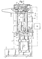
- the rheometer has a base 1 which is mounted on a pair of wheels, one of which is shown at 2 and on a foot 3 to enable it to be tipped up onto the wheels 2 and moved about if required.
- the base 1 supports an outer casing 4 which encloses most of the working parts of the rheometer and it also carries a main supporting framework 5.
- the supporting framework 5 includes a bottom plate 6 and a plate 7 which are the end plates of a pneumatic cylinder 9 and are fixed to each other by a cylinder wall 8 of the pneumatic cylinder which also has a piston rod 10.
- Another plate 11 is supported above the plate 7 by columns 12 and yet another plate 13 is fixed above the plate 11 by three tubes 14, 15 and 16, the disposition of which is best shown in Figure 3.
- Three rods 17, 18 and 19 are slidable upwards and downwards in the tubes 14, 15 and 16 respectively and have their lower ends fixed to a cross-head 20 which is itself fixed on the upper end of the piston rod 10 so that the rods 17-19 are movable upwards and downwards by the pneumatic cylinder 9.
- an upper platen 21, which lies within an upper cover 22 is pivotally mounted between the upper ends of the rods 18 and 19.
- the upper platen 21 carries an upper die 24 and the lower platen 23 carries a lower die 25.
- the upper and lower dies 24 and 25 form the two parts of a housing which, when the two dies are closed together as shown in Figures 2 and 6, enclose a chamber 26 between them.
- the chamber 26 contains a cylindrical disc-like rotor 27 which is mounted on a spindle 28 (see Figure 2).
- the spindle 28 has a lower portion 29 of square cross section which fits in a recess of similar cross section in a head 30 which is fixed in a rotor driving shaft 31.
- the shaft 31 has a bore 32 and is rotatably mounted in an upper bearing 33 carried in the platen 23 and in a lower bearing 34 carried by the plate 11.
- a driving unit 35 for driving the shaft 31 and through it the rotor27 is rotatably mounted on the shaft 31.
- the unit 35 comprises a gearbox 36 which is rotatably mounted on the shaft 31 by an upper bearing 38 and a lower bearing 39.
- the gearbox 36 supports an upper pulse-operated electric stepping motor 40 and a lower pulse-operated electric stepping motor 41.
- the motor 40 has a shaft 42 with a driving pinion 43 which meshes with the larger part of a double pinion 44.
- the smaller part of the double pinion 44 meshes with an upper gear wheel 45 of a differential gear 46.
- the lower motor 41 has a shaft 47 with a pinion 48 meshing with a double pinion 49 which in turn meshes with a lower gear wheel 50 of the differential gear 46.
- the pinions 44 and 49 are rotatably mounted by needle bearings on a fixed shaft 51 and the gear wheels 45 and 50 are mounted on the rotor shaft 31 by means of bearings 52 and 53 respectively.
- the gear wheels 45 and 50 have bevel gear portions 54 and 55 respectively and these mesh with two planetary bevel pinions 56 and 57.
- the pinions 56 and 57 are rotatably mounted on stub shafts 58 and 59 which are fixed to and project radially from the pinion shaft 31.
- the planetary pinions 56 and 57 will move around the stationary one of the two gear wheels 45 and 50, that is to say the planetary pinions will orbit and the rotor shaft 31 and with it the rotor 27 will be rotated.
- the rotor 27 can similarly be rotated, but at a lower speed merely by rotating one of the motors 40 or 41 faster than the other. What is more, by first rotating the motor 40 faster than the motor 41, the rotor 27 will be rotated in one direction and then by rotating the motor 41 faster than the motor 40, the rotor 27 will be rotated in an opposite direction. Thus by varying the speed of rotation of the motors 40 and 41, but without stopping either of these motors, the rotor 27 can be rotated continuously in either direction or it may be oscillated to and fro with any required frequency and speed solely in dependence upon the frequency of the pulses delivered to the motors 40 and 41.
- the upper end of the rod 17 has a peripheral groove 63 which forms one part of a catch.
- the upper platen 21 and the cover 22 which is attached to the platen 21 by a bracket 64, are acted upon by a gas strut 65 which counterbalances the platen 21 and the parts which it carries about its pivot 66 and also by a small pneumatic cylinder 67.
- a second catch part 68 containing a socket for receiving the upper end of the rod 17 and a small pneumatic ram, which is not shown, are fixed to the underside of the upper platen 21 and with the rods 17-19 raised by the pneumatic cylinder 9 acting through the cross head 20, and the pneumatic cylinder 67 extended, the platen 21 assumes the raised position shown in Figure 4.
- This provides easy access to the chamber 26 in the lower die 25. With this easy access, the rotor with its spindle 28 can be lifted out of the socket in the upper end of the shaft 31 and the chamber 26 can be cleaned.
- part of a sample to be tested is then inserted into the chamber 26 and the rotor 27 is then replaced in position.
- a further part of the sample to be tested is then placed over the rotor 27 and after this has been done, the pneumatic cylinder 67 is retracted to turn the upper platen 21 and the parts which it carries about the pivot 66 into the position shown in Figure 5.
- the catch in the part 68 is caused to engage by its pneumatic ram in the groove at the upper end of the rod 17.
- the chamber 26 is still open, but the upper die 24 is situated immediately above the lower die 25.
- the pneumatic cylinder 9 is operated to retract its piston rod 10 and lower the cross head 20, which in turn pulls the rods 17 to 19 downwards and this pulls the upper platen 21 downwards to compress the sample to be tested in the chamber 26 and close the chamber completely.
- the pneumatic cylinders 9 and 67 and the pneumatic cylinder which operates the catch 68 are supplied with compressed air from a supply, which is not shown, under the control of solenoid valves which are also not shown.
- These solenoid valves together with the motors 40 and 41 are in turn controlled by an electronic controller 69, which is indicated in Figure 1.
- the controller 69 contains conventional electronic circuitry and this circuitry includes circuits for controlling the solenoid valves which operate the various pneumatic cylinders, pulsing circuits for energising the motors 40 and 41 and in addition a circuit with a digital read out which indicates via the load cell 60, the torque which acts upon the gearbox 36 and thus also the torque acting upon the rotor 27.
- the controller 69 also contains a timing device which is connected to the circuits of the motors 40 and 41 and the circuit of the load cell 60 so that the time between any movements of the rotor 27 as provided by the motors 40 and 41 and the instants of zero or maximum torque as indicated by the load cell 60 can be measured.
- both the dies 24 and 25 are provided with electrical heating devices which are not shown. These may or may not be used as required.
- a sample of rubber or of a synthetic elastomer is inserted into and held under pressure in, the chamber 27 in the manner already described.
- the sample is then subjected to a substantial angular shearing strain by rotating the rotor 27 through an angle which is greater than the total angle of recovery of the sample when the torque applied to it through the rotor 27 is released.
- This angular shearing strain is applied by rotating the rotor 27 by operation of either one or both of the motors 40 and 41.
- the angle of rotation of the rotor 27 is indicated by an indicator on the controller 69 in dependence upon the number of pulses applied to either one or both of the motors.
- the rotation of the rotor 27 is then stopped and this may be done by stopping both of the motors 40 and 41, but it is preferably done by continuing to rotate both the motors, but at identical speeds and in opposite directions to each other.
- the rotor is then rotated in a reverse direction by one step through a predetermined angle by the application to one motor of a single pulse or predetermined number of pulses greater than the number of pulses applied to the other motor. In this example this step is equal to 1.8 minutes of arc. As the reverse rotation takes place, there will be a momentary torque exerted by the sample on the rotor in the forward direction and this is indicated by the controller through the load cell 60.
- the time taken for the torque applied to the rotor by the sample to fall to zero and then to increase to a maximum in the reverse direction is measured by the timing device in the controller.
- the rotor is again rotated in forward direction through one or more steps until a minimum observable torque upon the rotor by the sample is again indicated by the load cell.
- the angle of recovery of the sample is taken as the mean angle between that after the last step of reverse rotation of the rotor has taken place and that after the forward rotation has taken until the minimum observable torque is indicated.
- This testing technique may be repeated time after time as the sample, which may be initially completely uncured or unvulcanised, is cured or vulcanised by heating the dies 24 and 25.
- This example of the rheometer in accordance with the invention has the further great advantage that in addition to being able to carry out the testing method just described, it can also be used to carry out tests similar to those made by the well-known Mooney Viscometer by continuously rotating the rotor in one direction and measuring gradually increasing torque required to produce this rotation. It may also be used to carry out tests which have in the past been made by the conventional type of oscillating disc rheometer as described in GB-A-1036904. What is more the rheometer in accordance with the invention has the advantage over the conventional oscillating disc rheometer that the angle through which the rotor is oscillated may be varied during the course of the test by varying the speeds of rotation of the two motors 40 and 41.
- the sample may be subjected to large angles of strain at the start of its test and the angles of strain can be progressively reduced as the sample is vulcanised or cured.
- Variation of the angle of oscillation during the course of a test is not possible with a rheometer as described in GB-A-1036904.
- the variation of the angle of oscillation of the rotor during the course of the test gives more accurate test results during the stage of testing while the sample is viscous than those that can be obtained with a conventional oscillating disc rheometer since the conventional oscillating disc rheometer must have its oscillation set at an amplitude which is applicable to the sample when in its cured state and this amplitude is too small for accuracy when the sample is in its viscous state.
- the rheometer illustrated in Figure 7 of the drawings is constructed and can be operated in very much the same way as the first example described with reference to Figures 1 to 6 of the drawings, but in place of the gearbox 36 with its differential gear 46 and two pulse-operated stepping motors 40 and 41, the example shown in Figure 7 is provided with a simplified drive.
- This comprises a gearbox 136 which is rotatably mounted on the shaft 31' by means of bearings 138 and 139.
- the gearbox 137 carries a single reversible pulse-operated stepping motor 140 which has a driving shaft 142 with a pinion 143.
- the pinion 143 meshes with the larger part of a double pinion 144 which is rotatably mounted on a shaft 151.
- the smaller part of the double pinion 144 meshes with a gear wheel 152 which is permanently keyed to the rotor shaft 31'.
- the rotor 27 may be rotated step by step in one direction or in a reverse direction or it may be oscillated as in the first example, but these different modes of driving can only be effected by stopping and starting the motor 140.
- This is not so efficient as the drive in the first example with the two separate stepping motors which drive the shaft 31 through a differential gear because pulse-operated stepping motors have considerable starting inertia and, what is more, when oscillation of the shaft 31 is taking place, only parts of the peripheries of the pinions 144 and 152 are in use and in consequence these pinions are liable to suffer over a period of time from uneven wear which can upset the accuracy of the rheometer.
Landscapes
- General Health & Medical Sciences (AREA)
- General Physics & Mathematics (AREA)
- Life Sciences & Earth Sciences (AREA)
- Chemical & Material Sciences (AREA)
- Analytical Chemistry (AREA)
- Biochemistry (AREA)
- Immunology (AREA)
- Physics & Mathematics (AREA)
- Health & Medical Sciences (AREA)
- Pathology (AREA)
- Investigating Strength Of Materials By Application Of Mechanical Stress (AREA)
- Saccharide Compounds (AREA)
- Oscillators With Electromechanical Resonators (AREA)
- Ticket-Dispensing Machines (AREA)
Claims (12)
Priority Applications (1)
| Application Number | Priority Date | Filing Date | Title |
|---|---|---|---|
| AT84304169T ATE30473T1 (de) | 1983-07-15 | 1984-06-20 | Rheometer und verfahren zur benutzung desselben. |
Applications Claiming Priority (2)
| Application Number | Priority Date | Filing Date | Title |
|---|---|---|---|
| GB8319195 | 1983-07-15 | ||
| GB838319195A GB8319195D0 (en) | 1983-07-15 | 1983-07-15 | Pheometer |
Publications (2)
| Publication Number | Publication Date |
|---|---|
| EP0132056A1 EP0132056A1 (de) | 1985-01-23 |
| EP0132056B1 true EP0132056B1 (de) | 1987-10-28 |
Family
ID=10545786
Family Applications (1)
| Application Number | Title | Priority Date | Filing Date |
|---|---|---|---|
| EP84304169A Expired EP0132056B1 (de) | 1983-07-15 | 1984-06-20 | Rheometer und Verfahren zur Benutzung desselben |
Country Status (5)
| Country | Link |
|---|---|
| US (1) | US4559812A (de) |
| EP (1) | EP0132056B1 (de) |
| AT (1) | ATE30473T1 (de) |
| DE (1) | DE3467040D1 (de) |
| GB (1) | GB8319195D0 (de) |
Cited By (1)
| Publication number | Priority date | Publication date | Assignee | Title |
|---|---|---|---|---|
| EP1219948A3 (de) * | 2000-12-19 | 2011-06-29 | Malvern Instruments Limited | Rheometer mit Regelkreis |
Families Citing this family (19)
| Publication number | Priority date | Publication date | Assignee | Title |
|---|---|---|---|---|
| DE3636872A1 (de) * | 1986-10-30 | 1988-05-11 | Messerschmitt Boelkow Blohm | Geraet zur ermittlung der gelierzeit |
| US4794788A (en) * | 1987-10-05 | 1989-01-03 | Monsanto Company | Method and apparatus for rheological testing |
| US5103679A (en) * | 1990-07-10 | 1992-04-14 | The B. F. Goodrich Company | Method and apparatus for determining the fundamental viscoelastic properties of a material |
| SE9201665D0 (sv) * | 1992-05-27 | 1992-05-27 | Quality Measurement Devic | Anordning och foerfarande foer i vulkaniseringsutrustning inbyggd och kontinuerlig maetning, oevervakning och styrning av vulkaniseringsgrad samt av parametrar, vilka staar i samband med vulkaniserade foeremaals fysikaliska egenskaper |
| US5396804A (en) * | 1993-10-12 | 1995-03-14 | Gas Research Institute | Apparatus and method for force-controlled fatigue testing |
| FI101019B (fi) * | 1995-02-27 | 1998-03-31 | Janesko Oy | Mittauslaite aineen reologisten ominaisuuksien mittausta varten |
| GB9518176D0 (en) * | 1995-09-06 | 1995-11-08 | Watson William F | Rubber testing |
| DE19542920A1 (de) * | 1995-11-17 | 1997-05-22 | Asea Brown Boveri | Eisen-Nickel-Superlegierung vom Typ IN 706 |
| US5652376A (en) * | 1996-07-05 | 1997-07-29 | Dow Corning Corporation | Method of measuring yield stress |
| GB9624264D0 (en) * | 1996-11-21 | 1997-01-08 | Malaysian Rubber Producers | Method of measuring theological properties of a material and device therefor |
| US5920005A (en) * | 1997-08-01 | 1999-07-06 | Moss; Arthur L. | Geosynthetic liner testing apparatus and method |
| US8256272B1 (en) * | 2009-12-23 | 2012-09-04 | Western Digital (Fremont), Llc | UV adhesive viscosity adjustment apparatus and method |
| DE102013207184A1 (de) * | 2013-04-20 | 2014-10-23 | Anton Paar Gmbh | Doppelmotorrheometer mit Dehnanordnung |
| WO2016060928A1 (en) * | 2014-10-14 | 2016-04-21 | Alpha Technologies Services Llc | Rheometer system with decoupled cross-head |
| US10837874B2 (en) * | 2016-03-21 | 2020-11-17 | Abaco Drilling Technologies, LLC | Stall simulator for PDM performance testing device |
| US11821510B1 (en) | 2016-09-02 | 2023-11-21 | Eskridge, Inc. | Gearbox torque sensor |
| CN110361301B (zh) * | 2018-06-28 | 2022-04-22 | 廊坊立邦涂料有限公司 | 一种平整/装饰表面的半固体材料的流变性能测试方法 |
| CN110361299B (zh) * | 2018-06-28 | 2022-04-22 | 廊坊立邦涂料有限公司 | 一种平整/装饰表面的半固体材料的流变性能测试方法 |
| CN121898952A (zh) * | 2025-10-09 | 2026-04-21 | 南通绿萌食品有限公司 | 一种食品标准化的流变特性检测仪 |
Family Cites Families (10)
| Publication number | Priority date | Publication date | Assignee | Title |
|---|---|---|---|---|
| GB1051596A (de) * | 1900-01-01 | |||
| US2037529A (en) * | 1932-08-11 | 1936-04-14 | Us Rubber Co | Plastometer |
| GB578496A (en) * | 1944-09-05 | 1946-07-01 | Henleys Telegraph Works Co Ltd | Improvements in instruments for measuring properties of rubber and rubber-like materials |
| US3182494A (en) * | 1962-10-17 | 1965-05-11 | Goodrich Co B F | Viscurometer |
| GB1036904A (en) * | 1962-10-18 | 1966-07-20 | Monsanto Co | Measuring apparatus for determining the properties of plastic materials |
| US3282091A (en) * | 1963-10-29 | 1966-11-01 | James E Webb | Instrument for measuring torsional creep and recovery |
| US3535914A (en) * | 1969-02-07 | 1970-10-27 | Goodrich Co B F | Continuous shear dynamometer |
| US3688568A (en) * | 1970-07-28 | 1972-09-05 | Goodrich Co B F | Viscurometer |
| US3769830A (en) * | 1972-09-01 | 1973-11-06 | Goodrich Co B F | Viscurometer |
| GB1587706A (en) * | 1978-05-09 | 1981-04-08 | Avon Rubber Co Ltd | Testing rubber |
-
1983
- 1983-07-15 GB GB838319195A patent/GB8319195D0/en active Pending
-
1984
- 1984-06-08 US US06/618,856 patent/US4559812A/en not_active Expired - Fee Related
- 1984-06-20 AT AT84304169T patent/ATE30473T1/de active
- 1984-06-20 EP EP84304169A patent/EP0132056B1/de not_active Expired
- 1984-06-20 DE DE8484304169T patent/DE3467040D1/de not_active Expired
Cited By (1)
| Publication number | Priority date | Publication date | Assignee | Title |
|---|---|---|---|---|
| EP1219948A3 (de) * | 2000-12-19 | 2011-06-29 | Malvern Instruments Limited | Rheometer mit Regelkreis |
Also Published As
| Publication number | Publication date |
|---|---|
| DE3467040D1 (en) | 1987-12-03 |
| US4559812A (en) | 1985-12-24 |
| EP0132056A1 (de) | 1985-01-23 |
| GB8319195D0 (en) | 1983-08-17 |
| ATE30473T1 (de) | 1987-11-15 |
Similar Documents
| Publication | Publication Date | Title |
|---|---|---|
| EP0132056B1 (de) | Rheometer und Verfahren zur Benutzung desselben | |
| US5456118A (en) | Gyratory compactor | |
| US5606133A (en) | Gyratory compactor with mold specimen extruder | |
| EP0041375B1 (de) | Rheometer mit bewegter Form und Form zur Verwendung in einem solchen Rheometer | |
| US3681980A (en) | Oscillating disk rheometer | |
| KR920011037B1 (ko) | 점탄성 물질의 특성을 측정하기 위한 방법과 장치 | |
| EP0227573B1 (de) | Gerät und Verfahren zur Messung von rheologischen/viskoelastischen Eigenschaften einer vulkanisierten Kautschukprobe | |
| US3488992A (en) | Curometer | |
| US4335615A (en) | Equipment for testing materials for stress corrosion cracking | |
| US3494172A (en) | Cone curemeter | |
| CN210863005U (zh) | 一种防护效果好的弹簧压力值测试机 | |
| US4539838A (en) | Variable volume dual action rheometer | |
| JPS6260641B2 (de) | ||
| US4109516A (en) | Cam plastometer | |
| US3982427A (en) | Apparatus for working and testing solid elastomers | |
| GB2205959A (en) | Stress testing materials | |
| US3400595A (en) | Drive mechanism for converting rotary to oscillating motion | |
| CN217637908U (zh) | 一种大推力振动台转向机构 | |
| Atkinson | Simple and inexpensive pressure control equipment for conventional and stress path triaxial testing of soils | |
| CN220583758U (zh) | 一种机器人球关节用齿轮装配检测装置 | |
| CN223727400U (zh) | 一种用于低阻尼磁流体密封的阻尼测试装置 | |
| CN224137087U (zh) | 一种vvt扭转测试机 | |
| Yavari et al. | Simple reverse bending machine for low cycle fatigue at elevated temperatures | |
| CN120093249B (zh) | 一种用于电子血压计的检测器械及其方法 | |
| CN220542606U (zh) | 谐波减速器耐磨性检测器 |
Legal Events
| Date | Code | Title | Description |
|---|---|---|---|
| PUAI | Public reference made under article 153(3) epc to a published international application that has entered the european phase |
Free format text: ORIGINAL CODE: 0009012 |
|
| AK | Designated contracting states |
Designated state(s): AT BE CH DE FR GB IT LI LU NL SE |
|
| 17P | Request for examination filed |
Effective date: 19850709 |
|
| 17Q | First examination report despatched |
Effective date: 19861027 |
|
| GRAA | (expected) grant |
Free format text: ORIGINAL CODE: 0009210 |
|
| AK | Designated contracting states |
Kind code of ref document: B1 Designated state(s): AT BE CH DE FR GB IT LI LU NL SE |
|
| PG25 | Lapsed in a contracting state [announced via postgrant information from national office to epo] |
Ref country code: NL Effective date: 19871028 Ref country code: LI Effective date: 19871028 Ref country code: IT Free format text: LAPSE BECAUSE OF FAILURE TO SUBMIT A TRANSLATION OF THE DESCRIPTION OR TO PAY THE FEE WITHIN THE PRESCRIBED TIME-LIMIT;WARNING: LAPSES OF ITALIAN PATENTS WITH EFFECTIVE DATE BEFORE 2007 MAY HAVE OCCURRED AT ANY TIME BEFORE 2007. THE CORRECT EFFECTIVE DATE MAY BE DIFFERENT FROM THE ONE RECORDED. Effective date: 19871028 Ref country code: FR Free format text: THE PATENT HAS BEEN ANNULLED BY A DECISION OF A NATIONAL AUTHORITY Effective date: 19871028 Ref country code: CH Effective date: 19871028 Ref country code: BE Effective date: 19871028 Ref country code: AT Effective date: 19871028 |
|
| REF | Corresponds to: |
Ref document number: 30473 Country of ref document: AT Date of ref document: 19871115 Kind code of ref document: T |
|
| PG25 | Lapsed in a contracting state [announced via postgrant information from national office to epo] |
Ref country code: SE Effective date: 19871031 |
|
| REF | Corresponds to: |
Ref document number: 3467040 Country of ref document: DE Date of ref document: 19871203 |
|
| REG | Reference to a national code |
Ref country code: CH Ref legal event code: PL |
|
| EN | Fr: translation not filed | ||
| NLV1 | Nl: lapsed or annulled due to failure to fulfill the requirements of art. 29p and 29m of the patents act | ||
| PG25 | Lapsed in a contracting state [announced via postgrant information from national office to epo] |
Ref country code: LU Free format text: LAPSE BECAUSE OF NON-PAYMENT OF DUE FEES Effective date: 19880630 |
|
| PLBE | No opposition filed within time limit |
Free format text: ORIGINAL CODE: 0009261 |
|
| STAA | Information on the status of an ep patent application or granted ep patent |
Free format text: STATUS: NO OPPOSITION FILED WITHIN TIME LIMIT |
|
| 26N | No opposition filed | ||
| PG25 | Lapsed in a contracting state [announced via postgrant information from national office to epo] |
Ref country code: GB Effective date: 19890620 |
|
| GBPC | Gb: european patent ceased through non-payment of renewal fee | ||
| PG25 | Lapsed in a contracting state [announced via postgrant information from national office to epo] |
Ref country code: DE Effective date: 19900301 |