EP0132149A1 - Foret hélicoidal - Google Patents
Foret hélicoidal Download PDFInfo
- Publication number
- EP0132149A1 EP0132149A1 EP84304867A EP84304867A EP0132149A1 EP 0132149 A1 EP0132149 A1 EP 0132149A1 EP 84304867 A EP84304867 A EP 84304867A EP 84304867 A EP84304867 A EP 84304867A EP 0132149 A1 EP0132149 A1 EP 0132149A1
- Authority
- EP
- European Patent Office
- Prior art keywords
- drill
- chisel
- helical groove
- edge
- cutting
- Prior art date
- Legal status (The legal status is an assumption and is not a legal conclusion. Google has not performed a legal analysis and makes no representation as to the accuracy of the status listed.)
- Granted
Links
Images

Classifications
-
- B—PERFORMING OPERATIONS; TRANSPORTING
- B23—MACHINE TOOLS; METAL-WORKING NOT OTHERWISE PROVIDED FOR
- B23B—TURNING; BORING
- B23B51/00—Tools for drilling machines
- B23B51/02—Twist drills
-
- B—PERFORMING OPERATIONS; TRANSPORTING
- B23—MACHINE TOOLS; METAL-WORKING NOT OTHERWISE PROVIDED FOR
- B23B—TURNING; BORING
- B23B2251/00—Details of tools for drilling machines
- B23B2251/18—Configuration of the drill point
-
- B—PERFORMING OPERATIONS; TRANSPORTING
- B23—MACHINE TOOLS; METAL-WORKING NOT OTHERWISE PROVIDED FOR
- B23B—TURNING; BORING
- B23B2251/00—Details of tools for drilling machines
- B23B2251/18—Configuration of the drill point
- B23B2251/182—Web thinning
Definitions
- This invention relates to a twist drill having specific chisel edges at its point, more particularly to a twist drill subjected to less drilling thrust, offering good cutting quality in a cutting operation, and having sufficient strength and rigidity.
- the length of the thinning cut is one-half to three-fourths that of the cutting lip.
- the cut therefore extends far up the top end of the flute.
- the average distance of the thinning cut may be one-fourth to one-half of the drill diameter. It is also often recommended to extend the thinning out to the extreme edge in order to change the shape of the chip. In this case, a selectively positive or negative rake is rendered at the full length of the cutting edge.
- the object of this invention is to eliminate the above-mentioned disadvantages.
- the present invention aims to make available permanent chisel edges with an invariable and efficient rake surface, i.e., chisel edges which repeated regrinding of the drill point does not change the rake surface at all. By merely regrinding the point of a dull drill, the same or higher drilling effect can be obtained as with a drill having web thinning cuts. Therefore, troublesome thinning cut work can be eliminated.
- a twist drill characterized in that each of the chisel edges at the drill point is provided with a specific twisted wall surface functioning as the positive rake surface thereof and efficient in cutting.
- the surface is defined as an additional interior helical groove united to the original helical groove so as to extend over the full length of the drill body and to have the same lead of helix as the original helical groove of the drill body. It is preferable that the intersecting corners of the lips forming the main cutting edge and the chisel edge be chamfered or rounded off.
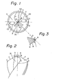
- 0 indicates the center of the point of a two-flute drill.
- Main cutting edges or cutting lips 1 and 2 stretch along lines AC and BD , respectively, extending from the chisel edge to the periphery of the drill.
- Chisel edges 3 and 4 are defined as approximately straight lines AU and BO , respectively, extending from the center 0 to the inner corners A and B of each lip.
- Numerals 5 and 6 respectively indicate relief surfaces ground with appropriate relief angles to the cutting lips 1 and 2. According to this invention, parts of the relief surfaces 5 and 6 also serve as seats of the built-up edge at the inner portion of the chisel edges 3 and 4.
- the essential feature of the invention resides in the formation of additional interior helical grooves 30 and 40 smoothly united to the original exterior helical groove over the entire length of the drill body so as to make available permanently efficient chisel edges.
- Each of the interior helical grooves 30 and 40 has the same lead length of helix as the original helical groove, thus the chisel edge always has a constant rake surface when reground.
- interior helical grooves are provided with a positive rake surface to the ch.isel edge at the drill point, thereby enabling efficient cutting action of the chisel edge.
- reference numeral 31 indicates a twisted wall surface forming the rake surface of the chisel edge 3. This forms a part of the interior helical groove 30 terminating in a curve AEG or BFH at the point of the drill.
- the rake surface of the chisel edge 3 usually is formed by the relief surface 6 of the opposite lip 2 and, accordingly, has a negative or minus rake angle, resulting in adverse cutting.
- Two different types of efficient rake surfaces are formed along the chisel edge line: Representing one are the outer chisel edge portions AE, BF extending toward the drill center 0 from the inner corners A, B of the lips 1, 2 through intermediate points E, F of the chisel edge. These outer portions AE and SF have wall surfaces of the helical grooves 31, 41 adjacent to the lip, which serve as a sole rake surface. Representing the other type are the ) inner chisel edges EO , FO from the intermediate points E, F to the drill center 0. These portions have combined rake surfaces comprising narrow triangular regions for the relief surfaces 6, 5 of the opposite lips 2, 1 and part of the wall surfaces of the helical grooves 31, 41 separated by curved edges EG, FH from the region.
- FIG. 3 illustrates one section of the combined rake surfaces, including an optional point K in the inner chisel edge EO .
- Line RP remains as the primary rake surface having a minus rake angle with regard to the rake surface 6.
- Line PQ is included in the twisted wall surface 31 having a positive rake angle.
- line KP is short enough, a built-up edge 9 with effective cutting action may be created over the region, thereby protecting the chisel edge from becoming dull.
- the greater part of the narrow region including line KP serves as a stable seating face for creating the hard built-up edge. Further, further the built-up edge is smoothly connected to the secondary rake surface having the positive rake angle with an efficiently sharp cutting edge.
- the chisel edge is given the above-mentioned specific rake surface, whenever the point of the drill becomes dull and the relief surface of the lips is reground, the predetermined accurate rake surface of the chisel edge is constantly obtained.
- the drill can be designed for a larger amount of offset W of the cutting lip line and, thus, a greater length of the chisel edge.
- the design of lips having a larger offset W means an increase of the web thickness, resulting in greater strength and rigidity of the drill.
- An appropriate design can more than compensate for the reduction of strength and rigidity of the drill due to the partial removal of material around the web for the formation of the interior helical grooves.
- Another advantage of the present invention relates to chip formation.
- a long continuous chip often winds up around the drill, making chip disposal difficult.
- this problem is eliminated.
- Test results show that, even when drilling holes in ductile workpieces such as steel, the twist drill of the present invention produces chip fragments rather than long chips.
- the mechanism behind this fragmentation in actual cutting it is believed that two different types of chips, one from the lips and the other from the chisel cutting edges, are produced. These are believed to flow in a slightly different direction, thereby interfering with each other and thereby fragmenting.
- the thinning cut is limited to the chisel edge area at the web end of the drill in consideration of not decreasing the stiffness of the drill. Due to this, the present invention solves various problems around the chisel edge in one stroke. This is, the formation of interior groove walls for producing a permanent positive rake surface to the chisel edge occurs principally over the full length of the flute in length. In addition, the bottom of the groove is located near the axis of the web.
- the cutting edge lines of the lip and the chisel edge make an obtuse angle at the crossing corner.
- the crossing corner between the lip and the chisel edge be finished by rounding off or chamfering, as is the practice in the design of general machining tools.
- the rake surface corresponding to the, for example, chamfered portion is defined as another twisted wall surface smoothly joined to both the lip and chisel edge wall surfaces in which the axial lead length of those helical grooves are all the same.
- Figures 4 and 5 illustrate an embodiment of the joining comer connected by a chamfered portion having a comparatively larger width of chamfer.
- the chamfered portion is contoured by a straight line segment cutting off the comer between the lip line and the chisel edge line. That is to say, on the lower side of the horizontal axis, the portion stretching from point 14 in the lip line 1 to point 34 in the chisel edge line 3 and, on the upper side thereof, the portion stretching from point 24 to 44 function as intermediate effective cutting edges.
- the length of the chisel edge after chamfering then becomes smaller than the original length as shown in section 34 , 44 .
- the grooves are preferably formed over the full length of the drill. However, if a larger strength is desired, they may be limited to the middle of the drill.
Landscapes
- Engineering & Computer Science (AREA)
- Mechanical Engineering (AREA)
- Drilling Tools (AREA)
Applications Claiming Priority (2)
| Application Number | Priority Date | Filing Date | Title |
|---|---|---|---|
| JP130314/83 | 1983-07-19 | ||
| JP58130314A JPS6025608A (ja) | 1983-07-19 | 1983-07-19 | ツイストドリル |
Publications (2)
| Publication Number | Publication Date |
|---|---|
| EP0132149A1 true EP0132149A1 (fr) | 1985-01-23 |
| EP0132149B1 EP0132149B1 (fr) | 1987-09-30 |
Family
ID=15031356
Family Applications (1)
| Application Number | Title | Priority Date | Filing Date |
|---|---|---|---|
| EP84304867A Expired EP0132149B1 (fr) | 1983-07-19 | 1984-07-17 | Foret hélicoidal |
Country Status (4)
| Country | Link |
|---|---|
| EP (1) | EP0132149B1 (fr) |
| JP (1) | JPS6025608A (fr) |
| KR (1) | KR920008792B1 (fr) |
| DE (1) | DE3466483D1 (fr) |
Cited By (4)
| Publication number | Priority date | Publication date | Assignee | Title |
|---|---|---|---|---|
| WO1996027469A1 (fr) * | 1995-03-03 | 1996-09-12 | Komet Präzisionswerkzeuge Robert Breuning Gmbh | Outil de forage |
| WO1997040953A1 (fr) * | 1996-05-02 | 1997-11-06 | Sandvik Ab | Foret |
| CN1087987C (zh) * | 1996-05-02 | 2002-07-24 | 桑德维克公司 | 钻头 |
| WO2022179709A1 (fr) | 2021-02-26 | 2022-09-01 | Gripp-X B.V. | Foret |
Families Citing this family (5)
| Publication number | Priority date | Publication date | Assignee | Title |
|---|---|---|---|---|
| JPS6384807A (ja) * | 1986-09-26 | 1988-04-15 | Kobe Steel Ltd | ドリル |
| JPH01164626U (fr) * | 1988-05-10 | 1989-11-16 | ||
| JPH0534620U (ja) * | 1991-10-11 | 1993-05-07 | ミツミ電機株式会社 | スイツチ装置 |
| SE507842C2 (sv) * | 1992-09-24 | 1998-07-20 | Sandvik Ab | Borr |
| CN103128346B (zh) * | 2013-03-19 | 2015-11-25 | 大连远东工具有限公司 | 具有螺旋状切削后刀面的麻花钻 |
Citations (1)
| Publication number | Priority date | Publication date | Assignee | Title |
|---|---|---|---|---|
| US2778252A (en) * | 1956-09-26 | 1957-01-22 | Nat Twist Drill & Tool Company | Self-thinned heavy-duty twist drill structure |
Family Cites Families (1)
| Publication number | Priority date | Publication date | Assignee | Title |
|---|---|---|---|---|
| JPS5633215A (en) * | 1979-08-22 | 1981-04-03 | Daijietsuto Kogyo Kk | Twist drill |
-
1983
- 1983-07-19 JP JP58130314A patent/JPS6025608A/ja active Granted
-
1984
- 1984-07-17 EP EP84304867A patent/EP0132149B1/fr not_active Expired
- 1984-07-17 DE DE8484304867T patent/DE3466483D1/de not_active Expired
- 1984-07-18 KR KR1019840004204A patent/KR920008792B1/ko not_active Expired
Patent Citations (1)
| Publication number | Priority date | Publication date | Assignee | Title |
|---|---|---|---|---|
| US2778252A (en) * | 1956-09-26 | 1957-01-22 | Nat Twist Drill & Tool Company | Self-thinned heavy-duty twist drill structure |
Cited By (6)
| Publication number | Priority date | Publication date | Assignee | Title |
|---|---|---|---|---|
| WO1996027469A1 (fr) * | 1995-03-03 | 1996-09-12 | Komet Präzisionswerkzeuge Robert Breuning Gmbh | Outil de forage |
| US6012881A (en) * | 1995-03-03 | 2000-01-11 | Komet Praezisionswerkzeuge Robert Breuning Gmbh | Drilling tool |
| WO1997040953A1 (fr) * | 1996-05-02 | 1997-11-06 | Sandvik Ab | Foret |
| US5807041A (en) * | 1996-05-02 | 1998-09-15 | Sandvik Ab | Drill having a pointed center cutting edge formed on a fluted shank |
| CN1087987C (zh) * | 1996-05-02 | 2002-07-24 | 桑德维克公司 | 钻头 |
| WO2022179709A1 (fr) | 2021-02-26 | 2022-09-01 | Gripp-X B.V. | Foret |
Also Published As
| Publication number | Publication date |
|---|---|
| JPS625727B2 (fr) | 1987-02-06 |
| EP0132149B1 (fr) | 1987-09-30 |
| DE3466483D1 (en) | 1987-11-05 |
| KR850001045A (ko) | 1985-03-14 |
| JPS6025608A (ja) | 1985-02-08 |
| KR920008792B1 (ko) | 1992-10-09 |
Similar Documents
| Publication | Publication Date | Title |
|---|---|---|
| US4688972A (en) | Twist drill | |
| US4671710A (en) | Drill bit | |
| US6957935B2 (en) | Cutting insert with curved cutting edge | |
| EP0817695B1 (fr) | Piece rapportee pour fraise a queue a bout spherique | |
| RU2277458C2 (ru) | Сверло | |
| US5226761A (en) | Metal cutting insert and metal cutting tool utilizing the metal cutting insert | |
| JP3215429B2 (ja) | オフセット切削エッジを有する螺旋状切削差し込み工具 | |
| JP4063338B2 (ja) | 切削加工用カッティングインサート | |
| US5709509A (en) | Cutting insert | |
| JP2000084708A (ja) | 切り屑を形成する機械加工用の切削チップ | |
| KR19990087448A (ko) | 둥근 모서리를 가진 절삭 인서트 | |
| US20040253062A1 (en) | Milling Tool | |
| EP0747156A1 (fr) | Plaquette de coupe et outil de coupe pour fraisage | |
| US5664914A (en) | Drill | |
| JPH1086003A (ja) | 多角形として形成された切削チップ | |
| US5755536A (en) | indexable cutting insert | |
| EP0132149B1 (fr) | Foret hélicoidal | |
| US5176476A (en) | Router cutting bit | |
| US7252465B2 (en) | Drill for chip removing machining | |
| US5059069A (en) | Insert for thread cutting | |
| US2035298A (en) | Auger bit | |
| JP3515167B2 (ja) | ドリル | |
| JP2007050477A (ja) | 超高圧焼結体チップ付きドリル | |
| JP3515168B2 (ja) | ドリル | |
| EP0295946A1 (fr) | Foret à élément tranchant |
Legal Events
| Date | Code | Title | Description |
|---|---|---|---|
| PUAI | Public reference made under article 153(3) epc to a published international application that has entered the european phase |
Free format text: ORIGINAL CODE: 0009012 |
|
| AK | Designated contracting states |
Designated state(s): DE FR GB IT |
|
| 17P | Request for examination filed |
Effective date: 19850713 |
|
| 17Q | First examination report despatched |
Effective date: 19860414 |
|
| GRAA | (expected) grant |
Free format text: ORIGINAL CODE: 0009210 |
|
| AK | Designated contracting states |
Kind code of ref document: B1 Designated state(s): DE FR GB IT |
|
| ITF | It: translation for a ep patent filed | ||
| REF | Corresponds to: |
Ref document number: 3466483 Country of ref document: DE Date of ref document: 19871105 |
|
| ET | Fr: translation filed | ||
| PLBE | No opposition filed within time limit |
Free format text: ORIGINAL CODE: 0009261 |
|
| STAA | Information on the status of an ep patent application or granted ep patent |
Free format text: STATUS: NO OPPOSITION FILED WITHIN TIME LIMIT |
|
| 26N | No opposition filed | ||
| ITTA | It: last paid annual fee | ||
| PGFP | Annual fee paid to national office [announced via postgrant information from national office to epo] |
Ref country code: GB Payment date: 19960708 Year of fee payment: 13 |
|
| PGFP | Annual fee paid to national office [announced via postgrant information from national office to epo] |
Ref country code: FR Payment date: 19960717 Year of fee payment: 13 |
|
| PGFP | Annual fee paid to national office [announced via postgrant information from national office to epo] |
Ref country code: DE Payment date: 19960925 Year of fee payment: 13 |
|
| PG25 | Lapsed in a contracting state [announced via postgrant information from national office to epo] |
Ref country code: GB Free format text: LAPSE BECAUSE OF NON-PAYMENT OF DUE FEES Effective date: 19970717 |
|
| GBPC | Gb: european patent ceased through non-payment of renewal fee |
Effective date: 19970717 |
|
| PG25 | Lapsed in a contracting state [announced via postgrant information from national office to epo] |
Ref country code: FR Free format text: LAPSE BECAUSE OF NON-PAYMENT OF DUE FEES Effective date: 19980331 |
|
| PG25 | Lapsed in a contracting state [announced via postgrant information from national office to epo] |
Ref country code: DE Free format text: LAPSE BECAUSE OF NON-PAYMENT OF DUE FEES Effective date: 19980401 |
|
| REG | Reference to a national code |
Ref country code: FR Ref legal event code: ST |