EP0132169A1 - Procédé et dispositif pour la fabrication par coulée d'une couche optiquement homogène transparente à partir d'un mélange de composants - Google Patents
Procédé et dispositif pour la fabrication par coulée d'une couche optiquement homogène transparente à partir d'un mélange de composants Download PDFInfo
- Publication number
- EP0132169A1 EP0132169A1 EP84401216A EP84401216A EP0132169A1 EP 0132169 A1 EP0132169 A1 EP 0132169A1 EP 84401216 A EP84401216 A EP 84401216A EP 84401216 A EP84401216 A EP 84401216A EP 0132169 A1 EP0132169 A1 EP 0132169A1
- Authority
- EP
- European Patent Office
- Prior art keywords
- mixing
- mixer
- reaction
- components
- mixture
- Prior art date
- Legal status (The legal status is an assumption and is not a legal conclusion. Google has not performed a legal analysis and makes no representation as to the accuracy of the status listed.)
- Granted
Links
Images
Classifications
-
- B—PERFORMING OPERATIONS; TRANSPORTING
- B29—WORKING OF PLASTICS; WORKING OF SUBSTANCES IN A PLASTIC STATE IN GENERAL
- B29B—PREPARATION OR PRETREATMENT OF THE MATERIAL TO BE SHAPED; MAKING GRANULES OR PREFORMS; RECOVERY OF PLASTICS OR OTHER CONSTITUENTS OF WASTE MATERIAL CONTAINING PLASTICS
- B29B7/00—Mixing; Kneading
- B29B7/74—Mixing; Kneading using other mixers or combinations of mixers, e.g. of dissimilar mixers ; Plant
- B29B7/7461—Combinations of dissimilar mixers
-
- B—PERFORMING OPERATIONS; TRANSPORTING
- B01—PHYSICAL OR CHEMICAL PROCESSES OR APPARATUS IN GENERAL
- B01F—MIXING, e.g. DISSOLVING, EMULSIFYING OR DISPERSING
- B01F23/00—Mixing according to the phases to be mixed, e.g. dispersing or emulsifying
- B01F23/40—Mixing liquids with liquids; Emulsifying
- B01F23/49—Mixing systems, i.e. flow charts or diagrams
-
- B—PERFORMING OPERATIONS; TRANSPORTING
- B01—PHYSICAL OR CHEMICAL PROCESSES OR APPARATUS IN GENERAL
- B01F—MIXING, e.g. DISSOLVING, EMULSIFYING OR DISPERSING
- B01F25/00—Flow mixers; Mixers for falling materials, e.g. solid particles
- B01F25/40—Static mixers
- B01F25/42—Static mixers in which the mixing is affected by moving the components jointly in changing directions, e.g. in tubes provided with baffles or obstructions
- B01F25/43—Mixing tubes, e.g. wherein the material is moved in a radial or partly reversed direction
- B01F25/431—Straight mixing tubes with baffles or obstructions that do not cause substantial pressure drop; Baffles therefor
- B01F25/4317—Profiled elements, e.g. profiled blades, bars, pillars, columns or chevrons
-
- B—PERFORMING OPERATIONS; TRANSPORTING
- B01—PHYSICAL OR CHEMICAL PROCESSES OR APPARATUS IN GENERAL
- B01F—MIXING, e.g. DISSOLVING, EMULSIFYING OR DISPERSING
- B01F25/00—Flow mixers; Mixers for falling materials, e.g. solid particles
- B01F25/40—Static mixers
- B01F25/42—Static mixers in which the mixing is affected by moving the components jointly in changing directions, e.g. in tubes provided with baffles or obstructions
- B01F25/43—Mixing tubes, e.g. wherein the material is moved in a radial or partly reversed direction
- B01F25/431—Straight mixing tubes with baffles or obstructions that do not cause substantial pressure drop; Baffles therefor
- B01F25/43197—Straight mixing tubes with baffles or obstructions that do not cause substantial pressure drop; Baffles therefor characterised by the mounting of the baffles or obstructions
- B01F25/431971—Mounted on the wall
-
- B—PERFORMING OPERATIONS; TRANSPORTING
- B01—PHYSICAL OR CHEMICAL PROCESSES OR APPARATUS IN GENERAL
- B01F—MIXING, e.g. DISSOLVING, EMULSIFYING OR DISPERSING
- B01F27/00—Mixers with rotary stirring devices in fixed receptacles; Kneaders
- B01F27/27—Mixers with stator-rotor systems, e.g. with intermeshing teeth or cylinders or having orifices
- B01F27/272—Mixers with stator-rotor systems, e.g. with intermeshing teeth or cylinders or having orifices with means for moving the materials to be mixed axially between the surfaces of the rotor and the stator, e.g. the stator rotor system formed by conical or cylindrical surfaces
- B01F27/2721—Mixers with stator-rotor systems, e.g. with intermeshing teeth or cylinders or having orifices with means for moving the materials to be mixed axially between the surfaces of the rotor and the stator, e.g. the stator rotor system formed by conical or cylindrical surfaces provided with intermeshing elements
-
- B—PERFORMING OPERATIONS; TRANSPORTING
- B01—PHYSICAL OR CHEMICAL PROCESSES OR APPARATUS IN GENERAL
- B01F—MIXING, e.g. DISSOLVING, EMULSIFYING OR DISPERSING
- B01F27/00—Mixers with rotary stirring devices in fixed receptacles; Kneaders
- B01F27/60—Mixers with rotary stirring devices in fixed receptacles; Kneaders with stirrers rotating about a horizontal or inclined axis
- B01F27/70—Mixers with rotary stirring devices in fixed receptacles; Kneaders with stirrers rotating about a horizontal or inclined axis with paddles, blades or arms
- B01F27/707—Mixers with rotary stirring devices in fixed receptacles; Kneaders with stirrers rotating about a horizontal or inclined axis with paddles, blades or arms the paddles co-operating, e.g. intermeshing, with elements on the receptacle wall
-
- B—PERFORMING OPERATIONS; TRANSPORTING
- B01—PHYSICAL OR CHEMICAL PROCESSES OR APPARATUS IN GENERAL
- B01F—MIXING, e.g. DISSOLVING, EMULSIFYING OR DISPERSING
- B01F33/00—Other mixers; Mixing plants; Combinations of mixers
- B01F33/45—Magnetic mixers; Mixers with magnetically driven stirrers
- B01F33/453—Magnetic mixers; Mixers with magnetically driven stirrers using supported or suspended stirring elements
-
- B—PERFORMING OPERATIONS; TRANSPORTING
- B01—PHYSICAL OR CHEMICAL PROCESSES OR APPARATUS IN GENERAL
- B01F—MIXING, e.g. DISSOLVING, EMULSIFYING OR DISPERSING
- B01F33/00—Other mixers; Mixing plants; Combinations of mixers
- B01F33/80—Mixing plants; Combinations of mixers
- B01F33/82—Combinations of dissimilar mixers
-
- B—PERFORMING OPERATIONS; TRANSPORTING
- B29—WORKING OF PLASTICS; WORKING OF SUBSTANCES IN A PLASTIC STATE IN GENERAL
- B29B—PREPARATION OR PRETREATMENT OF THE MATERIAL TO BE SHAPED; MAKING GRANULES OR PREFORMS; RECOVERY OF PLASTICS OR OTHER CONSTITUENTS OF WASTE MATERIAL CONTAINING PLASTICS
- B29B7/00—Mixing; Kneading
- B29B7/30—Mixing; Kneading continuous, with mechanical mixing or kneading devices
- B29B7/32—Mixing; Kneading continuous, with mechanical mixing or kneading devices with non-movable mixing or kneading devices
- B29B7/325—Static mixers
-
- B—PERFORMING OPERATIONS; TRANSPORTING
- B29—WORKING OF PLASTICS; WORKING OF SUBSTANCES IN A PLASTIC STATE IN GENERAL
- B29B—PREPARATION OR PRETREATMENT OF THE MATERIAL TO BE SHAPED; MAKING GRANULES OR PREFORMS; RECOVERY OF PLASTICS OR OTHER CONSTITUENTS OF WASTE MATERIAL CONTAINING PLASTICS
- B29B7/00—Mixing; Kneading
- B29B7/30—Mixing; Kneading continuous, with mechanical mixing or kneading devices
- B29B7/34—Mixing; Kneading continuous, with mechanical mixing or kneading devices with movable mixing or kneading devices
- B29B7/38—Mixing; Kneading continuous, with mechanical mixing or kneading devices with movable mixing or kneading devices rotary
- B29B7/40—Mixing; Kneading continuous, with mechanical mixing or kneading devices with movable mixing or kneading devices rotary with single shaft
- B29B7/401—Mixing; Kneading continuous, with mechanical mixing or kneading devices with movable mixing or kneading devices rotary with single shaft having a casing closely surrounding the rotor, e.g. with a plunger for feeding the material
-
- B—PERFORMING OPERATIONS; TRANSPORTING
- B29—WORKING OF PLASTICS; WORKING OF SUBSTANCES IN A PLASTIC STATE IN GENERAL
- B29B—PREPARATION OR PRETREATMENT OF THE MATERIAL TO BE SHAPED; MAKING GRANULES OR PREFORMS; RECOVERY OF PLASTICS OR OTHER CONSTITUENTS OF WASTE MATERIAL CONTAINING PLASTICS
- B29B7/00—Mixing; Kneading
- B29B7/30—Mixing; Kneading continuous, with mechanical mixing or kneading devices
- B29B7/34—Mixing; Kneading continuous, with mechanical mixing or kneading devices with movable mixing or kneading devices
- B29B7/38—Mixing; Kneading continuous, with mechanical mixing or kneading devices with movable mixing or kneading devices rotary
- B29B7/40—Mixing; Kneading continuous, with mechanical mixing or kneading devices with movable mixing or kneading devices rotary with single shaft
- B29B7/402—Mixing; Kneading continuous, with mechanical mixing or kneading devices with movable mixing or kneading devices rotary with single shaft using a rotor-stator system with intermeshing elements, e.g. teeth
-
- B—PERFORMING OPERATIONS; TRANSPORTING
- B29—WORKING OF PLASTICS; WORKING OF SUBSTANCES IN A PLASTIC STATE IN GENERAL
- B29B—PREPARATION OR PRETREATMENT OF THE MATERIAL TO BE SHAPED; MAKING GRANULES OR PREFORMS; RECOVERY OF PLASTICS OR OTHER CONSTITUENTS OF WASTE MATERIAL CONTAINING PLASTICS
- B29B7/00—Mixing; Kneading
- B29B7/30—Mixing; Kneading continuous, with mechanical mixing or kneading devices
- B29B7/34—Mixing; Kneading continuous, with mechanical mixing or kneading devices with movable mixing or kneading devices
- B29B7/38—Mixing; Kneading continuous, with mechanical mixing or kneading devices with movable mixing or kneading devices rotary
- B29B7/40—Mixing; Kneading continuous, with mechanical mixing or kneading devices with movable mixing or kneading devices rotary with single shaft
- B29B7/405—Mixing heads
- B29B7/407—Mixing heads with a casing closely surrounding the rotor, e.g. with conical rotor
-
- B—PERFORMING OPERATIONS; TRANSPORTING
- B29—WORKING OF PLASTICS; WORKING OF SUBSTANCES IN A PLASTIC STATE IN GENERAL
- B29B—PREPARATION OR PRETREATMENT OF THE MATERIAL TO BE SHAPED; MAKING GRANULES OR PREFORMS; RECOVERY OF PLASTICS OR OTHER CONSTITUENTS OF WASTE MATERIAL CONTAINING PLASTICS
- B29B7/00—Mixing; Kneading
- B29B7/30—Mixing; Kneading continuous, with mechanical mixing or kneading devices
- B29B7/34—Mixing; Kneading continuous, with mechanical mixing or kneading devices with movable mixing or kneading devices
- B29B7/38—Mixing; Kneading continuous, with mechanical mixing or kneading devices with movable mixing or kneading devices rotary
- B29B7/40—Mixing; Kneading continuous, with mechanical mixing or kneading devices with movable mixing or kneading devices rotary with single shaft
- B29B7/405—Mixing heads
- B29B7/408—Mixing heads with mixing elements on a rotor co-operating with mixing elements, perpendicular to the axis of the rotor, fixed on a stator
-
- B—PERFORMING OPERATIONS; TRANSPORTING
- B29—WORKING OF PLASTICS; WORKING OF SUBSTANCES IN A PLASTIC STATE IN GENERAL
- B29B—PREPARATION OR PRETREATMENT OF THE MATERIAL TO BE SHAPED; MAKING GRANULES OR PREFORMS; RECOVERY OF PLASTICS OR OTHER CONSTITUENTS OF WASTE MATERIAL CONTAINING PLASTICS
- B29B7/00—Mixing; Kneading
- B29B7/74—Mixing; Kneading using other mixers or combinations of mixers, e.g. of dissimilar mixers ; Plant
- B29B7/7404—Mixing devices specially adapted for foamable substances
- B29B7/7409—Mixing devices specially adapted for foamable substances with supply of gas
- B29B7/7414—Mixing devices specially adapted for foamable substances with supply of gas with rotatable stirrer, e.g. using an intermeshing rotor-stator system
-
- B—PERFORMING OPERATIONS; TRANSPORTING
- B29—WORKING OF PLASTICS; WORKING OF SUBSTANCES IN A PLASTIC STATE IN GENERAL
- B29B—PREPARATION OR PRETREATMENT OF THE MATERIAL TO BE SHAPED; MAKING GRANULES OR PREFORMS; RECOVERY OF PLASTICS OR OTHER CONSTITUENTS OF WASTE MATERIAL CONTAINING PLASTICS
- B29B7/00—Mixing; Kneading
- B29B7/74—Mixing; Kneading using other mixers or combinations of mixers, e.g. of dissimilar mixers ; Plant
- B29B7/7404—Mixing devices specially adapted for foamable substances
- B29B7/7409—Mixing devices specially adapted for foamable substances with supply of gas
- B29B7/7419—Mixing devices specially adapted for foamable substances with supply of gas with static or injector mixer elements
- B29B7/7423—Mixing devices specially adapted for foamable substances with supply of gas with static or injector mixer elements preceded or followed by rotatable stirring device
-
- B—PERFORMING OPERATIONS; TRANSPORTING
- B29—WORKING OF PLASTICS; WORKING OF SUBSTANCES IN A PLASTIC STATE IN GENERAL
- B29B—PREPARATION OR PRETREATMENT OF THE MATERIAL TO BE SHAPED; MAKING GRANULES OR PREFORMS; RECOVERY OF PLASTICS OR OTHER CONSTITUENTS OF WASTE MATERIAL CONTAINING PLASTICS
- B29B7/00—Mixing; Kneading
- B29B7/74—Mixing; Kneading using other mixers or combinations of mixers, e.g. of dissimilar mixers ; Plant
- B29B7/7404—Mixing devices specially adapted for foamable substances
- B29B7/7409—Mixing devices specially adapted for foamable substances with supply of gas
- B29B7/7428—Methodical aspects
-
- B—PERFORMING OPERATIONS; TRANSPORTING
- B29—WORKING OF PLASTICS; WORKING OF SUBSTANCES IN A PLASTIC STATE IN GENERAL
- B29B—PREPARATION OR PRETREATMENT OF THE MATERIAL TO BE SHAPED; MAKING GRANULES OR PREFORMS; RECOVERY OF PLASTICS OR OTHER CONSTITUENTS OF WASTE MATERIAL CONTAINING PLASTICS
- B29B7/00—Mixing; Kneading
- B29B7/74—Mixing; Kneading using other mixers or combinations of mixers, e.g. of dissimilar mixers ; Plant
- B29B7/7476—Systems, i.e. flow charts or diagrams; Plants
- B29B7/7485—Systems, i.e. flow charts or diagrams; Plants with consecutive mixers, e.g. with premixing some of the components
-
- C—CHEMISTRY; METALLURGY
- C08—ORGANIC MACROMOLECULAR COMPOUNDS; THEIR PREPARATION OR CHEMICAL WORKING-UP; COMPOSITIONS BASED THEREON
- C08G—MACROMOLECULAR COMPOUNDS OBTAINED OTHERWISE THAN BY REACTIONS ONLY INVOLVING UNSATURATED CARBON-TO-CARBON BONDS
- C08G18/00—Polymeric products of isocyanates or isothiocyanates
- C08G18/06—Polymeric products of isocyanates or isothiocyanates with compounds having active hydrogen
- C08G18/08—Processes
-
- B—PERFORMING OPERATIONS; TRANSPORTING
- B01—PHYSICAL OR CHEMICAL PROCESSES OR APPARATUS IN GENERAL
- B01F—MIXING, e.g. DISSOLVING, EMULSIFYING OR DISPERSING
- B01F25/00—Flow mixers; Mixers for falling materials, e.g. solid particles
- B01F2025/91—Direction of flow or arrangement of feed and discharge openings
-
- Y—GENERAL TAGGING OF NEW TECHNOLOGICAL DEVELOPMENTS; GENERAL TAGGING OF CROSS-SECTIONAL TECHNOLOGIES SPANNING OVER SEVERAL SECTIONS OF THE IPC; TECHNICAL SUBJECTS COVERED BY FORMER USPC CROSS-REFERENCE ART COLLECTIONS [XRACs] AND DIGESTS
- Y10—TECHNICAL SUBJECTS COVERED BY FORMER USPC
- Y10S—TECHNICAL SUBJECTS COVERED BY FORMER USPC CROSS-REFERENCE ART COLLECTIONS [XRACs] AND DIGESTS
- Y10S261/00—Gas and liquid contact apparatus
- Y10S261/26—Foam
Definitions
- a catalyst and, where appropriate, other additives are added to the reaction mixture, such as, for example, a stabilizer, to increase resistance to ultraviolet rays.
- these additives are distributed uniformly in one of the reaction components before the reaction components are combined. It has been found that it is thus possible to avoid in the most secure manner possible homogeneity defects which are to be attributed to the supply of these additives.
- a device suitable for implementing the method according to the invention comprises in a particularly advantageous manner a dynamic mixer in which the mixing shaft is coupled to the drive apparatus by means of a coupling with permanent magnets, the reaction mixture flowing between the wall of the mixer casing and the magnetic coupling ring connected to the mixing shaft, so that the inner magnetic coupling ring is driven by a ring magneto coupling further enhanced by certain preferred arrangements of the devices used.
- the invention is based on the established fact that the use of known mixing methods does not lead to the desired result in the case of existing particular difficulties, but on the contrary that the manufacture of. dandruff-free films, i.e. streak-free films, are not possible in this way. If, for example, the static mixing process is used in which the various mixers known for mixing liquids are used in the laminar flow domain, it is observed that a relatively long mixing distance is necessary to ensure a sufficient mixture of reaction components. The reactive mixture, however, needs a relatively long time to travel this long mixing distance while the polyaddition process already begins.
- the object of the invention is to provide a process for mixing two or more components of a multi-component system - in particular a polyurethane casting resin, which, in the shortest possible time after the combination of the reaction components, ensures optimal homogeneity of the mixture satisfying the highest requirements.
- this object is achieved by the fact that the components. reaction are mixed, after their combination first in a mixer operating on the basis of the static principle, then in a dynamic mixer which immediately follows the static mixer.
- the process according to the invention gives transparent films or layers free of streaks of optimum optical quality. This result is achieved by a desired combination of two known mixing methods carried out in a determined order, the result of the mixing operation still being able to be improved.
- the present invention relates to a process for the production of optically homogeneous, highly transparent layers from a mixture of several components, in particular from a mixture of components which can be poured and reacts to give a polyurethane, according to which the reaction components, if necessary with the addition of a reaction catalyst, and the mixture is deposited on a casting substrate on which the layer performs its reaction.
- the invention further relates to a device for carrying out the method.
- plastic objects must meet extremely high requirements regarding the uniformity of the plastic. This is the case, for example, with layers, films or transparent plates which must allow vision without defect or distortion. Such highly transparent layers or films are used, for example, as protective layers against fragmentation on silicate glass panes or as layers improving abrasion resistance on plastic substrates. Such panes of safety glass or panes of plastic material insensitive to abrasion, as well as the manufacture of such layers from determined polyurethanes are described, for example, in documents DE-OS 20 58 504 and DE-AS 22 28 299 and 26 29 779.
- the homogeneity and thus the optical quality of the polyurethane layer is essentially determined by the mixing operation which immediately precedes the casting of the layer.
- the polyaddition reaction indeed begins and since the reacting fractions of the mixture entrained tick disposed outside of the mixer casing.
- a dynamic mixer of this construction has the advantage that the reaction mixture is drawn linearly through the mixer, so that an essentially linear flow of liquid is established because the mixer is devoid of so-called dead zones in which fractions of the reaction mixture can stay longer than others.
- the pressure of the reaction mixture passing through this mixer can be greatly increased without sealing difficulties arising.
- the higher pressure achieves increased flow rates, so that the residence time of the plastic reaction mixture in the mixer is shortened, which avoids the risk of early hardening or too strong polymerization of the reaction mixture, influencing the fluidity and the homogeneity of the plastic reaction mixture.
- the reaction mixture which leaves the mixer is of a completely homogeneous composition and is therefore entirely free of streaks.
- the mixing method according to the invention and the device described below in detail are suitable not only for mixing reaction resins, but also of course for mixing and homogenizing other systems, for example solvents and adhesives, when the mixture must meet particularly high requirements from the point of view of its homogeneity. This is always the case when these films or films must be free of streaks to guarantee vision without distortion.
- a polyether obtained by condensation of propylene oxide with a triol and having a molecular weight of approximately 450 and a content of free OH radicals is used as component K 1. from 10.5 to 12% and as component K 2, a biuret of 1,6-hexamethylenediisocyanate having a content of free NCO radicals of 21 to 22%.
- component K 1 has a viscosity at room temperature of 300 to 800 cP and component K 2 also at room temperature, a viscosity of 2000 to 14000 cP.
- the pourable mixture additionally, as UV stabilizer, 2,6-di-t-butyl-p-cresol in an amount of 2.3%, based on the amount of component K 1 and as an accelerator, dibutyltin dilaurate in an amount of 0.05%, based on the amount of component K 1.
- the components K 1 and K 2 are mixed one with the other. the other in a weight ratio of approximately 1: 1.
- a mixture of the additives that is to say of the stabilizer S and of the catalyst B, is prepared in the indicated ratio, and the following is introduced this mixture in the mixing device 3 by means of the metering pump 2 shown diagrammatically.
- the component K 1 is also introduced into this mixing device 3 by means of the metering pump 4, the metering pumps 2 and 4 being arranged so that the desired quantitative ratio to the mixture of stabilizer and catalyst, on the one hand, and of the component K 1, on the other hand, is maintained with precision.
- the mixing apparatus 3 as such can in principle be of any structure and is not a critical element of the process. Static mixers of the type of the static mixer 10, described in detail below, which follows the mixing chamber 1 have been found suitable for the mixing apparatus 3.
- the component K 1 mixed with the stabilizer and the catalyst flows in the mixing chamber. 1 from the mixing device 3.
- Component K 2 is also introduced into the mixing chamber 1, also with the aid of a metering pump 8 in the desired quantitative ratio.
- the function of the mixing chamber 1 is simply to combine the reaction components.
- check valves are provided (not shown) which prevent the direction of flow from changing in the event of pressure reversal.
- the pipe 9 which introduces the combined reaction components into the static mixer 10.
- the static mixer 10 which is shown in longitudinal section in FIG. 2, is formed by a tube 11 provided with flanges 12 and a length of 360 mm, in which are installed mixing elements 13, 14.
- the mixing elements 13, 14 with a length of 24 mm and a 12 mm diameter corresponding to the inner diameter of the tube 11, are formed of slats assembled and arranged in substance transversely to the direction of flow, while being offset each time by 90 ° from each other.
- Fifteen mixing elements 13 and 14 of this type are alternately placed in the tube 11.
- the slats of the mixing elements arranged across the direction of flow continuously cut the components to be mixed into layers and spread them over the entire section of the tube.
- the static mixer SULZER type SMX from the company Gebrüder Sulzer AG, Switzerland, and the N-FORM mixer from the company Bran & Lübbe from Hamburg have proved particularly suitable.
- FIG. 3 shows the mixer 21 with the retaining sleeve 22 stationary and the intake manifold 23 through which the fluid reaction mixture enters.
- the retaining sleeve 22 is provided with a through hole 24 which is connected to the intake manifold 23.
- a hole 25 connects to the through hole 24 and opens into a recess 35 -centred in the holding sleeve 22
- Part of the reaction mixture immediately flows through the bore 25 through the ball bearing 34 carrying the shaft 33 and thus ensures a continuous flushing of the bearing, which avoids dead zones of flow in the region of the bearing.
- the casing 26 of the mixer can be rigidly fixed the envelope 26. Preferably; two to four mixing rods are arranged distributed over the periphery of the casing 26 (Fig. 7).
- a coupling ring 45 is mounted to rotate on the casing.
- the coupling ring 45 is preferably mounted on the casing 26 by means of a bearing 46.
- the coupling ring 45 is connected by means of a pinion 47 to a motor, not shown, which drives the coupling ring 45.
- permanent magnets 48 are fitted all along the periphery in hollows, many permanent magnets being arranged parallel side by side.
- the permanent magnets in the external coupling ring 45 and in the annular sheath 37 are arranged in such a way that they are always oriented towards one another by opposite poles. When the permanent magnets arranged in the coupling ring. 45 are oriented with the south pole inward, the permanent magnets disposed in the annular sheath 37 are oriented with the north pole outward (see Fig. 6).
- the reaction mixture of fluid synthetic material reaches, via the intake manifold 23, the bore 24 in the retaining sleeve 22 and the annular intermediate space present between the internal coupling ring 32 and the envelope wall 26, in the mixing chamber 40 which is arranged downstream of the permanent magnet coupling. Part of the reaction mixture flows through the bore 25 immediately through the ball bearing 34.
- the reaction mixture undergoes, in the mixing chamber 40, a dynamic treatment and is mixed in a manner to the retaining sleeve 26, for example by a screw connection.
- the casing 26 is detachably closed by means of a cover 27.
- the cover 27 is provided with a bore 28 extending in the axial direction and with an outlet pipe 29 for the outlet of the reaction mixture. fluid synthetic material.
- a bore 30 having an inclination connects to the bore 28 and leads to the central recess 31 in which the shaft 33 journals.
- an internal coupling ring 32 which is rigidly connected to the shaft 33.
- the coupling ring 32 is rotatably mounted on a ball bearing 34 in the recess 35 of the retaining sleeve 22.
- Permanent magnets 36 are disposed around the entire periphery of the interior coupling ring and are fitted in hollows of an annular sheath 37 which can be inserted axially.
- the permanent magnets 36 are, for example, covered towards the outside (see FIG. 4) by a hollow cylinder 38 & thin wall which is, for example, made of a chemically resistant synthetic material.
- Mixing elements 39 are arranged on the mixing shaft 33 in the mixing chamber 40 at a certain distance from each other.
- the shaft 33 extends over the whole of the mixing chamber 40.
- the shaft 33 ends in the journal 41 which is rotatably mounted in the cover 27 in the bearings 42, 43.
- the reaction mixture leaving the mixing chamber flows, in part, through the bearings 42 and 43, through the bore 30, in the outlet pipe 29.
- mixing rods 44 In the region of the mixing chamber 40, between the rotating crosses 39 of the shaft 33, mixing rods 44, the ends of which penetrate into the mixing chamber 40, are inserted in the wall of intensive without dead zones being able to form in the coupling region near the bearings or in the mixing chamber.
- the reaction mixture leaves the mixing chamber 40 partly through the bearings 42 and 33 and partly via the bore 28 through the outlet pipe 29.
- the direction of flow of the reaction mixture is indicated by arrows.
- the direction of flow and the flow ratio in the permanent magnet coupling are shown in particular in FIG. 4.
- Fig. 3 clearly shows that the mixer shown does not have slippery seals which heat up during operation and thus cause too rapid polymerization at this location.
- the fluid synthetic reaction mixture flows almost linearly through the mixer without passing through dead zones, which is of particular importance for the production of an absolutely homogeneously mixed reaction mixture.
- the reaction mixture exiting through the outlet pipe 29 now exhibits optimal homogeneity. It is admitted via line 50 to the casting device 51.
- this casting device 51 it may be a device called a doctor blade casting head such as that shown, for example, in the document DE -PS 26 14 596. If it is intended to produce sheets from the reaction mixture, glass plates are advantageously used as the casting substrate 52. 52.1 reaction mixture is applied to this casting substrate in a layer of uniform thickness. After polymerization of the layer 53 with corresponding heating, the finished polyurethane sheet is torn off from the casting substrate 52.
Landscapes
- Chemical & Material Sciences (AREA)
- Chemical Kinetics & Catalysis (AREA)
- Engineering & Computer Science (AREA)
- Mechanical Engineering (AREA)
- Dispersion Chemistry (AREA)
- Polymers & Plastics (AREA)
- Medicinal Chemistry (AREA)
- Organic Chemistry (AREA)
- Health & Medical Sciences (AREA)
- Processing And Handling Of Plastics And Other Materials For Molding In General (AREA)
- Injection Moulding Of Plastics Or The Like (AREA)
- Mixers With Rotating Receptacles And Mixers With Vibration Mechanisms (AREA)
- Casting Or Compression Moulding Of Plastics Or The Like (AREA)
Abstract
Description
- mélange à couler, peut avoir des conséquences très défavorables pour l'opération de coulée elle-même, car la formation d'une couche coulée uniforme dans l'interstice de coulée est ainsi empêchée. Tous ces inconvénients ne sont évités que par la combinaison caractéristique de la présente invention, à savoir par le fai.t qu'après la réunion des composants de réaction ceux-ci parcourent d'abord une distance de mélange statique qui est si courte que seul un bon prémélange est réalisé en un temps court et que le mélange de réaction prémélangé de manière statique sans élévation de température est amené immédiatement ensuite à un dispositif mélangeur dynamique dans lequel le mélange est amené au degré d'homogénéisation requis.
- En règle générale, un catalyseur et le cas échéant d'autres additifs sont ajoutés au mélange de réaction,-comme par exemple un stabilisant, pour augmenter la résistance aux rayons ultraviolets. Dans une autre réalisation avantageuse de l'invention, ces additifs sont répartis uniformément dans un des composants de réaction avant que les composants de réaction soient réunis. Il s'est avéré que l'on peut ainsi éviter de la manière la plus sûre des défauts d'homogénéité éventuels qui sont à attribuer à l'apport de ces additifs.
- Un dispositif convenant pour la mise en oeuvre du procédé conforme à l'invention comporte d'une manière particulièrement avantageuse un mélangeur dynamique dans lequel l'arbre de mélange est couplé à l'appareil d'entraînement par l'intermédiaire d'un accouplement à aimants permanents, le mélange de réaction s'écoulant entre la paroi de l'enveloppe du mélangeur et l'anneau de couplage magnétique relié à l'arbre de mélange, de sorte que l'anneau de couplage magnétique intérieur est entraîné par un anneau de couplage magné- lioré davantage par certains agencements préférés des dispositifs utilisés.
- L'invention est basée sur le fait établi que l'utilisation des procédés de mélange connus n'aboutit pas au résultat souhaité dans le cas des difficultés particulières existantes, mais au contraire que la fabrication de. pellicules exemptes de distorsion optique, c'est-à-dire de pellicules sans stries, n'est de cette façon pas possible. Si l'on utilise, par exemple, le procédé de mélange statique dans lequel on emploie les divers mélangeurs connus pour le mélange de liquides dans le domaine d'écoulement laminaire, on observe qu'une distance de mélange rélativement longue est nécessaire pour assurer un mélange suffisant des constituants de réaction. Le mélange réactif a cependant besoin d'un temps relativement long pour parcourir cette longue distance de mélange tandis que le processus de polyaddition débute déjà. De plus, dans le cas de longues distances de mélange, les différences des temps de séjour des filets coulés individuels augmentent,de sorte que, vu sur toute la section, des conditions de réaction différentes existent à l'extrémité de la distance de mélange. Lorsque, -par contre, pour raccourcir le temps de mélange, on utilise un mélangeur dynamique en lieu et place d'un tube de mélange statique, le résultat n'est pas non plus satisfaisant. Ceci est dû au fait que, aux bas régimes, la qualité du mélange est insuffisante et que, d'autre part, aux hauts régimes, une élévation de température du mélange de réaction se produit par friction, ce qui crée localement des fractions de mélange à degré de polymérisation poussé, ce qui nuit considérablement aux propriétés optiques de la couche coulée. En conséquence, la réaction de polyaddition se. deroule dans son ensemble plus rapidement, ce qui, à cause de l'augmentation de la viscosité du présentent une viscosité différente de celle des constituants de réaction, des stries se forment à l'intérieur de la masse coulée et sont visibles dans la couche au terme de la réaction. Pour cette raison, un mélange aussi homogène que possible des composants. de réaction doit être effectué dans le temps le plus court possible lorsqu'on veut obtenir une réaction uniforme dans la masse coulée, c'est-à-dire éviter la formation de stries. Le mélange homogène des composants . de réaction est encore rendu difficile dans le cas du polyuréthanne par le fait que les deux composants ., à savoir le constituant polyol et le composant isocyanate, présentent des viscosités nettement différentes, la différence se mesurant selon un facteur compris entre-4 et 8 ou davantage.
- L'invention a pour but de procurer un procédé pour mélanger deux ou plus de deux composants d'un système à plusieurs composants--, en particulier d'une résine de coulée de polyuréthanne, qui, en un laps de temps le plus court possible après la combinaison des composants de réaction, assure une homogénéité optimale du mélange satisfaisant aux exigences les plus élevées.
- Suivant l'invention, ce but est réalisé par le fait que les composants . de réaction sont mélangés, après leur combinaison tout d'abord dans un mélangeur fonctionnant sur base du principe statique, puis dans un mélangeur dynamique qui suit immédiatement le mélangeur statique.
- Le procédé conforme à l'invention donne des pellicules ou couches transparentes exemptes de stries d'une qualité optique optimale. Ce résultat est atteint par une combinaison voulue de deux procédés de mélange connus mis en oeuvre dans un ordre déterminé, le résultat de l'opération de mélange pouvant encore être amé-
- La présente invention concerne un procédé pour la fabrication de couches optiquement homogènes, hautement transparentes à partir d'un mélange de plusieurs composants en particulier à partir d'un mélange de composants pouvant être coulé et réagissant pour donner un polyuréthanne, selon lequel on mélange les composants de réaction, le cas échéant avec addition d'un catalyseur de réaction, et on dépose le mélange sur un substrat de coulée sur lequel la couche effectue sa réaction. L'invention concerne en outre un dispositif pour l'exécution du procédé.
- Dans certains cas, des objets en matière plastique doivent respecter des exigences extrêmement élevées en ce qui concerne l'homogénéité de la matière plastique. Il en est ainsi, par exemple, de couches, pellicules ou plaques transparentes qui doivent permettre une vision sans défaut ni distorsion. De telles couches ou pellicules hautement transparentes s'utilisent, par exemple, comme couches de protection contre la fragmentation sur des vitres en verre au silicate ou comme couches améliorant la résistance à l'abrasion sur des substrats en matière plastique. De telles vitres en verre de sécurité ou vitres en matière plastique insensibles à l'abrasion, ainsi que la fabrication de telles couches à partir de polyuréthannes déterminés sont décrites, par exemple, dans les documents DE-OS 20 58 504 et DE-AS 22 28 299 et 26 29 779.
- Dans de tels procédés de coulée réactive de plusieurs composants, l'homogénéité et ainsi la qualité optique de la couche de polyuréthane est essentiellement déterminée par l'opération de mélange qui précède immédiatement la coulée de la couche. Au moment où les composants réactifs entrent en contact les uns avec les autres débute en effet la réaction de polyaddition et étant donné que les fractions du mélange qui réagissent tique entrainé disposé à l'extérieur of l'enveloppe du mélangeur. Un mélangeur dynamique de cette construction a l'avantage que le mélange de réaction est entraîné de manière linéaire à travers le mélangeur, de sorte qu'un flux de liquide essentiellement linéaire s'établit car le mélangeur est dépourvu de zones dites mortes dans lesquelles des fractions du mélange de réaction peuvent séjourner plus longtemps que d'autres. De plus, la pression du mélange de réaction traversant ce mélangeur peut être fortement accrue sans que des difficultés d'étanchéité surgissent. La pression plus élevée permet d'obtenir des vitesses d'écoulement accrues, de sorte que le temps de séjour-dû mélange de réaction de matière plastique dans le mélangeur est raccourci, ce qui permet d'éviter le risque d'un durcissement précoce ou d'une polymlérisation trop forte du mélange de réaction, influençant la fluidité et l'homogénéité du mélange de réaction de matière plastique. Le mélange de réaction qui quitte le mélangeur est d'une composition complètement homogène et est ainsi entièrement exempt de stries.
- Le procédé de mélange conforme à l'invention et le dispositif décrit plus loin en détail conviennent non seulement pour mélanger des résines de réaction, mais aussi bien entendu pour mélanger et homogénéiser d'autres systèmes, par exemple de solvants et d'adhésifs, lorsque le mélange doit respecter des exigences particulièrement élevées du point de vue de son homogénéité. Il en va toujours ainsi lorsque ces films ou pellicules doivent être exempts de stries pour garantir une vision sans distorsion.
- D'autres agencements et développements font l'objet des revendications 2 à 9.
- Une forme préférée d'exécution de l'invention est illustrée dans les dessins annexés et sera décrite ci-après dans le détail. Aux dessins annexés :
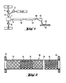
- la Fig. 1 est une vue schématique du déroulement du procédé conforme à l'invention;
- la Fig. 2 est une vue en coupe d'un tube mélangeur statique;
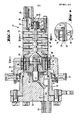
- la Fig. 3 est une vue en coupe longitudinale d'un mélangeur dynamique;
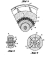
- la Fig. 4 illustre un détail IV de la Fig.3 , à plus grande échelle;
- la Fig. 5 est une vue en coupe fragmentaire du mélangeur dynamique suivant la ligne V-V de la Fig. 3;
- la Fig. 6 illustre le détail VI de la Fig. 5, à plus grande échelle, et
- la Fig. 7 est une vue en coupe de la chambre de mélange du mélangeur dynamique suivant la ligne VII-VII de la Fig. 3.
- Le déroulement du procédé est illustré schématiquement sur la Fig. 1. Pour fabriquer la résine de polyuréthanne pouvant être coulée, on utilise à titre de composant K l, un polyéther obtenu par condensation d'oxyde de propylène avec un triol et ayant un poids moléculaire d'environ 450 et une teneur en radicaux OH libres de 10,5 à 12% et en tant que composant K 2, un biuret de 1,6-hexaméthylènediisocyanate présentant une teneur en radicaux NCO libres de 21 à 22%. Le composant K 1 a une viscosité à la température ambiante de 300 à 800 cP et le composant K 2 également à la température ambiante, une viscosité de 2000 à 14000 cP. Pour produire le mélange pouvant être coulé, on ajoute en outre, à titre de stabilisant aux rayons ultraviolets, du 2,6-di-t-butyl-p-crésol en une quantité de 2,3%, sur base de la quantité du composant K 1 et à titre d'accélérateur , du dilaurate de dibutylétain en une quantité de 0,05%, sur base de la quantité du composant K 1. Les composants K 1 et K 2 sont mélangés l'un à l'autre selon un rapport pondéral d'environ 1:1.
- Avant de combiner les composants 1 et K 2 dans la chambre de mélange 1, on prépare tout d'abord un mélange des additifs, c'est-à-dire du stabilisant S et du catalyseur B, dans le rapport indiqué, et on introduit ce mélange dans l'appareil de' mélange 3 au moyen de la pompe doseuse 2 représentée schématiquement. Le composant K 1 est aussi introduit dans cet appareil de mélange 3 au moyen de la pompe doseuse 4, les pompes doseuses 2 et 4 étant agencées de telle sorte que le rapport quantitatif souhaité au mélange de stabilisant et du catalyseur , d'une part, et du composant K 1, d'autre part, soit maintenu avec précision. L'appareil de mélange 3 comme tel peut en principe être de n'importe quelle structure et ne constitue pas un élément critique du procédé. Des mélangeurs statiques du type du mélangeur statique 10, décrit en détail plus loin, qui suit la chambre de mélange 1 se sont avérés convenables pour l'appareil de mélange 3. Le composant K 1 mélangé au stabilisant et au catalyseur s'écoule dans la chambre de mélange. 1 à partir de l'appareil de mélange 3.
- Le composant K 2 est aussi introduit dans la chambre de mélange l,et ce également à l'aide d'une pompe doseuse 8 dans le rapport quantitatif souhaité.
- La chambre de mélange 1 a simplement pour fonction de combiner les composants de réaction. Dans les conduites d'amenée des deux composants _ sont prévues des valves de retenue (non représentées) qui empêchent que le sens de l'écoulement change en cas d'inversion de pression. A la tubulure de sortie est raccordé le tuyau 9 qui introduit les composants de réaction combinés dans le mélangeur statique 10.
- Le mélangeur statique 10, qui est représenté en coupe longitudinale sur la Fig. 2, est formé d'un tube 11 pourvu de brides 12 et d'une longueur de 360 mm, dans lequel sont installés des éléments mélangeurs 13, 14. Les éléments mélangeurs 13, 14 d'une longueur de 24 mm et d'un diamètre de 12 mm correspondant au diamètre intérieur du tube 11, sont formés de lattes assemblées et disposées en substance transversalement à la direction d'écoulement,tout en étant décalées chaque fois de 90° l'une de l'autre. Quinze éléments mélangeurs 13 et 14 de ce type sont disposés au total dans le tube 11 en alternance. Les lattes des éléments mélangeurs disposées en travers de la direction d'écoulement coupent continuellement les composants à mélanger en couches et les étalent sur toute la section du tube.
- A cet effet, le mélangeur statique SULZER, type SMX de la Société Gebrüder Sulzer AG, Suisse, et le mélangeur N-FORM de la Société Bran & Lübbe de Hambourg se sont avérés particulièrement convenables.
- Immédiatement après son passage dans le mélangeur statique 10, le mélange de réaction est introduit dans le mélangeur dynamique 21, qui est représenté en détail dans les Fig. 3 à 7. La Fig. 3 montre le mélangeur 21 avec la douille de retenue 22 immobile et la tubulure d'admission 23 par laquelle le mélange de réaction fluide pénètre. La douille de retenue 22 est pourvue d'une forure de traversée 24 qui est raccordée à la tubulure d'admission 23. Une forure 25 se branche sur la forure de traversée 24 et débouche dans un évidement 35 -centré dans la douille de retenue 22. Une partie du mélange de réaction s'écoule immédiatement par la forure 25 à travers le roulement à billes 34 portant l'arbre 33 et assure ainsi un rinçage continu du palier, ce qui évite des zones mortes d'écoulement dans la région du palier. L'enveloppe 26 du mélangeur peut être fixée rigidement l'enveloppe 26. De préférence; deux à quatre tiges de mélange sont disposées réparties sur la périphérie de l'enveloppe 26 (Fig. 7).
- A l'extérieur de l'enveloppe 26, à la hauteur de l'anneau 32, un anneau de couplage 45 est monté tournant sur l'enveloppe. L'anneau de couplage 45 est de préférence monté sur l'enveloppe 26 par l'intermédiaire d'un palier 46. L'anneau de couplage 45 est relié par l'intermédiaire d'un pignon 47 à un moteur, non représenté, qui entraîne l'anneau de couplage 45. Dans la surface annulaire de l'anneau de couplage qui est orientée vers l'enveloppe 26 et qui est disposée au-dessus de l'anneau 32, des aimants permanents 48 sont emboîtés tout le long de la périphérie dans des creux, de nombreux aimants permanents étant disposés parallèlement côte à côte. Les aimants permanents dans l'anneau de couplage extérieur 45 et dans la gaine annulaire 37 sont disposés de telle manière qu'ils sont toujours orientés l'un vers l'autre par des pôles opposés. Lorsque les aimants permanents disposés dans l'anneau de couplage.45 sont orientés avec le pôle sud vers l'intérieur, les aimants permanents disposés dans la gaine annulaire 37 sont orientés avec le pôle nord vers l'extérieur(voir Fig. 6).
- Le mélange de réaction de matière synthétique fluide parvient, par l'intermédiaire de la tubulure d'admission 23,de la forure 24 dans la douille de retenue 22 et de l'espace intermédiaire annulaire présent entre l'anneau de couplage intérieur 32 et la paroi d'enveloppe 26,dans la chambre de mélange 40 qui est disposée en aval de l'accouplement à aimants permanents. Une partie du mélange de réaction s'écoule par la forure 25 immédiatement à travers le roulement à billes 34. Le mélange de réaction subit, dans la chambre de mélange 40, un traitement dynamique et est mélangé de manière à la douille de retenue 26, par exemple par une liaison vissée. L'enveloppe 26 est fermée de manière détachable au moyen d'un couvercle 27. Le couvercle 27 est pourvu d'une forure 28 s'étendant dans le sens axial et d'une tubulure de sortie 29 pour la sortie du mélange de réaction de matière synthétique fluide. Une forure 30 présentant une inclinaison se branche sur la forure 28 et mène à l'évidement 31 central dans lequel tourillonne l'arbre 33. Dans l'enveloppe 26 est disposé un anneau de couplage intérieur 32, qui est relié rigidement à l'arbre 33. L'anneau de couplage 32 est monté à rotation sur un roulement à billes 34 dans l'évidement 35 de la douille de retenue 22. Des aimants permanents 36 sont disposés sur toute la périphérie de l'anneau de couplage intérieur et sont emboîtés dans des creux d'une gaine annulaire 37 pouvant être insérée axialement. Les aimants permanents 36 sont, par exemple, recouverts vers l'extérieur (voir Fig. 4) par un cylindre creux 38 & paroi mince qui est, par exemple, constitué d'une matière synthétique chimiquement résistante.
- Des éléments mélangeurs 39, en particulier des croix mélangeuses, sont disposés sur l'arbre de mélange 33 dans la chambre de mélange 40 à une certaine distance l'un de l'autre. L'arbre 33 s'étend sur l'ensemble de la chambre de mélange 40. L'arbre 33 se termine dans le tourillon 41 qui est monté à rotation dans le couvercle 27 dans les paliers 42, 43. Le mélange de réaction quittant la chambre de mélange s'écoule, pour partie, par les paliers 42 et 43,par l'intermédiaire de la forure 30, dans la tubulure de sortie 29.
- Dans la région de la chambre de mélange 40, entre les croix tournantes 39 de l'arbre 33, des tiges de mélange 44, dont les extrémités pénètrent dans la chambre de mélange 40, sont insérées dans la paroi de intensive sans que des zones mortes puissent se former dans la région de couplage à proximité des paliers ou dans la chambre de mélange. Le mélange de réaction quitte la chambre de mélange 40 pour partie par l'intermédiaire des paliers 42 et 33 et pour partie par l'intermédiaire de la forure 28 par la tubulure de sortie 29. Le sens d'écoulement du mélange de réaction est indiqué par des flèches. Le sens d'écoulement et le rapport d'écoulement dans l'accouplement à aimants permanents sont en particulier représentés à la Fig. 4.
- La Fig. 3 montre clairement que le mélangeur représenté ne comporte pas de joints d'étanchéité glissants qui s'échauffent pendant le fonctionnement et provoquent ainsi une polymérisation trop rapide à cet endroit. Le mélange de réaction de matière synthétique fluide s'écoule de manière quasi linéaire à travers le mélangeur sans traverser des zones mortes, ce qui est d'une importance particulière pour la production d'un mélange de réaction mélangé de manière absolument homogène.
- Le mélange de réaction sortant par la tubulure de sortie 29 présente maintenant une homogénéité optimale. Il est admis par la conduite 50 au dispositif de coulée 51. Dans le cas de ce dispositif de coulée 51, il peut s'agir d'un dispositif appelé tête de coulée à racle tel que celui représenté, par exemple, dans le document DE-PS 26 14 596. Au cas où il est prévu de produire des feuilles à partir du mélange de réaction, on utilise avantageusement, comme substrat de coulée 52, des plaques de verre. On applique sur ce substrat de coulée 52,1e mélange de réaction en une couche d'une épaisseur uniforme. Après polymérisation de la couche 53 avec chauffage correspondant, on arrache la feuille de polyuréthanne finie du substrat de coulée 52.
Claims (9)
Applications Claiming Priority (2)
| Application Number | Priority Date | Filing Date | Title |
|---|---|---|---|
| FR8309839A FR2548043A1 (fr) | 1983-06-14 | 1983-06-14 | Procede et dispositif pour la fabrication par coulee d'une couche optiquement homogene transparente a partir d'un melange de composants |
| FR8309839 | 1983-06-14 |
Publications (2)
| Publication Number | Publication Date |
|---|---|
| EP0132169A1 true EP0132169A1 (fr) | 1985-01-23 |
| EP0132169B1 EP0132169B1 (fr) | 1987-09-09 |
Family
ID=9289772
Family Applications (1)
| Application Number | Title | Priority Date | Filing Date |
|---|---|---|---|
| EP84401216A Expired EP0132169B1 (fr) | 1983-06-14 | 1984-06-14 | Procédé et dispositif pour la fabrication par coulée d'une couche optiquement homogène transparente à partir d'un mélange de composants |
Country Status (6)
| Country | Link |
|---|---|
| US (1) | US4590030A (fr) |
| EP (1) | EP0132169B1 (fr) |
| JP (1) | JPS6071205A (fr) |
| CA (1) | CA1245028A (fr) |
| DE (1) | DE3465887D1 (fr) |
| FR (1) | FR2548043A1 (fr) |
Cited By (12)
| Publication number | Priority date | Publication date | Assignee | Title |
|---|---|---|---|---|
| US4732725A (en) * | 1985-01-15 | 1988-03-22 | Saint-Gobain Vitrage | Process and device for the production of a safety pane |
| EP0268810B1 (fr) * | 1986-10-24 | 1990-08-08 | Spritztechnik AG | Dispositif pour mélanger et doser des composants de résine synthétique et procédé pour faire marcher ce dispositif |
| EP0397788A4 (en) * | 1988-01-29 | 1991-07-10 | Applied Biosystems, Inc. | Device for mixing solutions |
| EP0614812A1 (fr) * | 1993-03-12 | 1994-09-14 | Dow Corning Corporation | Ensemble de buse mélangeur |
| WO1996009881A1 (fr) * | 1994-09-27 | 1996-04-04 | Nordson Corporation | Procede et appareil de production d'une mousse cellulaire |
| EP0842695A1 (fr) * | 1996-11-14 | 1998-05-20 | Nippon Shokubai Co., Ltd. | Procédé et dispositif pour la production d'un produit de particules de résine et produit de particules de résine |
| WO2004007062A3 (fr) * | 2002-07-11 | 2004-04-01 | Zsolt Herbak | Dispositif pour melanger des liquides |
| WO2004067816A1 (fr) * | 2003-01-29 | 2004-08-12 | Saurer Gmbh & Co. Kg | Dispositif et procede pour filer des fibres colorees |
| WO2007073475A1 (fr) * | 2005-12-16 | 2007-06-28 | Prc-Desoto International, Inc. | Systeme de melange et procede de compositions thermodurcies comprenant des melangeurs statiques et rotatifs |
| EP1892033A1 (fr) * | 2006-08-21 | 2008-02-27 | ZHERMACK S.p.A. | Dispositif et procédé pour mélanger une substance à plusieurs composants pour des pièces coulées dentaires |
| US7731413B2 (en) | 2008-02-20 | 2010-06-08 | Zhermack S.P.A. | Mixer for multi-components substance for dental casting |
| RU2455957C2 (ru) * | 2008-02-20 | 2012-07-20 | Жермак С.П.А. | Смеситель |
Families Citing this family (30)
| Publication number | Priority date | Publication date | Assignee | Title |
|---|---|---|---|---|
| FR2576011B1 (fr) * | 1985-01-15 | 1991-10-31 | Saint Gobain Vitrage | Procede et dispositif pour la fabrication d'un vitrage de securite |
| US4950148A (en) * | 1987-01-31 | 1990-08-21 | Kabushiki Kaisha Cubic Engineering | Apparatus for manufacturing silicone gel sheet |
| US5092523B1 (en) * | 1989-02-21 | 1996-11-12 | Sybron Chemicals | Magnetic drive tank cleaning apparatus |
| DE59104667D1 (de) * | 1990-08-23 | 1995-03-30 | Sulzer Chemtech Ag | Statische Laminar-Mischeinrichtung, Zumischvorrichtung, sowie Verwendung von Mischeinrichtung und Zumischvorrichtung. |
| US5114732A (en) * | 1991-04-02 | 1992-05-19 | Kraft General Foods, Inc. | Method of mixing viscous emulsions |
| US5225168A (en) * | 1991-09-03 | 1993-07-06 | Caterpillar Inc. | Static mixing apparatus |
| US5393546A (en) * | 1993-02-26 | 1995-02-28 | Rich-Seapak Corporation | Method for two phase conveyance of a product |
| US6405759B1 (en) * | 1997-08-05 | 2002-06-18 | Owens Corning Composites Sprl | Apparatus for the continuous preparation of glass fiber sizing compositions |
| CA2304096C (fr) * | 1997-09-18 | 2003-09-09 | Pacira Pharmaceuticals, Inc. | Compositions anesthesiques de liposomes a liberation prolongee |
| JPH11172082A (ja) * | 1997-11-10 | 1999-06-29 | Teijin Ltd | 改質ポリエステルの連続製造方法 |
| AU752802C (en) | 1997-11-14 | 2006-04-13 | Pacira Pharmaceuticals, Inc. | Production of multivesicular liposomes |
| KR100397934B1 (ko) * | 2000-12-01 | 2003-09-19 | 기아자동차주식회사 | 연속 혼합식 제독제 생성장치 |
| GB0222194D0 (en) * | 2002-09-25 | 2002-10-30 | Porvair Plc | Polymer film production |
| DE10345099A1 (de) * | 2003-09-26 | 2005-04-21 | Basf Ag | Verfahren zur Herstellung von Mischungen zur Polyurethan-Herstellung |
| US20050094482A1 (en) * | 2003-10-31 | 2005-05-05 | Nordson Corporation | Method and apparatus for producing closed cell foam |
| DE10357182A1 (de) * | 2003-12-06 | 2005-06-30 | Bayer Materialscience Ag | Verfahren zum schonenden Eintragen von Additiven, Katalysatoren oder Inhibitoren in Polymerschmelzen |
| ATE495814T1 (de) * | 2005-09-13 | 2011-02-15 | Bayone Urethane Systems Llc | Dynamischer schneckenmischer und diesen verwendende mischvorrichtung und mischverfahren |
| JP5205097B2 (ja) * | 2007-06-18 | 2013-06-05 | 旭サナック株式会社 | 多液混合装置 |
| JP2012061677A (ja) * | 2010-09-15 | 2012-03-29 | Fujifilm Corp | 混合装置、流延ドープの製造方法及び溶液製膜方法 |
| JP5779454B2 (ja) * | 2010-09-15 | 2015-09-16 | 富士フイルム株式会社 | 混合装置、流延ドープの製造方法及び溶液製膜方法 |
| FI20155036A (fi) * | 2015-01-19 | 2016-07-20 | Outotec Finland Oy | Menetelmä ja sekoituslaite ensimmäisen nesteen ja toisen nesteen sekoittamiseksi dispersioon |
| AT516946B1 (de) * | 2015-07-03 | 2016-10-15 | Sonderhoff Eng Gmbh | Mischvorrichtung |
| US12151024B2 (en) | 2021-01-22 | 2024-11-26 | Pacira Pharmaceuticals, Inc. | Manufacturing of bupivacaine multivesicular liposomes |
| US11033495B1 (en) | 2021-01-22 | 2021-06-15 | Pacira Pharmaceuticals, Inc. | Manufacturing of bupivacaine multivesicular liposomes |
| US11278494B1 (en) | 2021-01-22 | 2022-03-22 | Pacira Pharmaceuticals, Inc. | Manufacturing of bupivacaine multivesicular liposomes |
| US11357727B1 (en) | 2021-01-22 | 2022-06-14 | Pacira Pharmaceuticals, Inc. | Manufacturing of bupivacaine multivesicular liposomes |
| EP4415713A4 (fr) | 2021-10-14 | 2025-08-06 | Pacira Pharmaceuticals Inc | Formulations de liposomes multivésiculaires de bupivacaïne et leurs utilisations |
| US12280149B1 (en) | 2024-05-20 | 2025-04-22 | Pacira Pharmaceuticals, Inc. | Manufacturing of bupivacaine multivesicular liposomes |
| US12156940B1 (en) | 2024-05-20 | 2024-12-03 | Pacira Pharmaceuticals, Inc. | Manufacturing of bupivacaine multivesicular liposomes |
| US12251472B1 (en) | 2024-05-20 | 2025-03-18 | Pacira Pharmaceuticals, Inc. | Manufacturing of bupivacaine multivesicular liposomes |
Citations (7)
| Publication number | Priority date | Publication date | Assignee | Title |
|---|---|---|---|---|
| US2556854A (en) * | 1949-10-29 | 1951-06-12 | Standard Oil Dev Co | Magnetic coupling drive for highpressure stirred reactors |
| FR1211689A (fr) * | 1957-10-07 | 1960-03-17 | American Viscose Corp | Mélangeur du type à engrenages notamment pour l'industrie des fibres textiles synthétiques |
| GB1047731A (en) * | 1963-03-04 | 1966-11-09 | Pacific Vegets Le Oil Corp | Improvements in or relating to the production of plastic foam |
| FR2134377A1 (fr) * | 1971-04-29 | 1972-12-08 | Sulzer Ag | |
| FR2398606A1 (fr) * | 1976-07-02 | 1979-02-23 | Saint Gobain | Feuille en matiere plastique utilisee pour la fabrication de vitrages feuilletes |
| GB2086249A (en) * | 1980-10-13 | 1982-05-12 | Toyo Engineering Corp | Mixing apparatus |
| US4330215A (en) * | 1979-05-03 | 1982-05-18 | Rubber & Plastics Research Assoc Of Gb | Mixing device |
Family Cites Families (10)
| Publication number | Priority date | Publication date | Assignee | Title |
|---|---|---|---|---|
| US2868518A (en) * | 1957-01-08 | 1959-01-13 | Du Pont | Mixer |
| US3111389A (en) * | 1959-10-22 | 1963-11-19 | Chrysler Corp | Apparatus for preparing polyurethane foam compositions and the like |
| DE2058504C2 (de) * | 1970-11-27 | 1982-11-25 | Bayer Ag, 5090 Leverkusen | Verfahren zum Kratzfestmachen von schlagfesten und klar durchsichtigen Kunststoffen |
| DE2228299C3 (de) * | 1972-06-09 | 1985-11-14 | Saint-Gobain Industries, Neuilly-sur-Seine | Sicherheitsglasscheibe |
| DE2534740C3 (de) * | 1975-08-04 | 1983-02-03 | Franz 4630 Bochum Klaus | Spaltrohrkreiselpumpe |
| US4065234A (en) * | 1975-12-22 | 1977-12-27 | Nihon Kagaku Kizai Kabushiki Kaisha | Magnetically driven rotary pumps |
| DE2614596C3 (de) * | 1976-04-05 | 1980-03-13 | Vereinigte Glaswerke Gmbh, 5100 Aachen | Abstreichgießkopf zum Aufbringen gießfähiger Kunststoffschichten auf plane Unterlagen |
| DE2624058C2 (de) * | 1976-05-28 | 1984-11-15 | Franz Klaus-Union, 4630 Bochum | Permanentmagnetpumpe |
| JPS5518130A (en) * | 1978-07-24 | 1980-02-08 | Mitsubishi Electric Corp | Offset circuit |
| JPS5731941U (fr) * | 1980-07-31 | 1982-02-19 |
-
1983
- 1983-06-14 FR FR8309839A patent/FR2548043A1/fr not_active Withdrawn
-
1984
- 1984-06-06 US US06/617,814 patent/US4590030A/en not_active Expired - Fee Related
- 1984-06-12 JP JP59119222A patent/JPS6071205A/ja active Granted
- 1984-06-14 DE DE8484401216T patent/DE3465887D1/de not_active Expired
- 1984-06-14 EP EP84401216A patent/EP0132169B1/fr not_active Expired
- 1984-06-14 CA CA000456605A patent/CA1245028A/fr not_active Expired
Patent Citations (7)
| Publication number | Priority date | Publication date | Assignee | Title |
|---|---|---|---|---|
| US2556854A (en) * | 1949-10-29 | 1951-06-12 | Standard Oil Dev Co | Magnetic coupling drive for highpressure stirred reactors |
| FR1211689A (fr) * | 1957-10-07 | 1960-03-17 | American Viscose Corp | Mélangeur du type à engrenages notamment pour l'industrie des fibres textiles synthétiques |
| GB1047731A (en) * | 1963-03-04 | 1966-11-09 | Pacific Vegets Le Oil Corp | Improvements in or relating to the production of plastic foam |
| FR2134377A1 (fr) * | 1971-04-29 | 1972-12-08 | Sulzer Ag | |
| FR2398606A1 (fr) * | 1976-07-02 | 1979-02-23 | Saint Gobain | Feuille en matiere plastique utilisee pour la fabrication de vitrages feuilletes |
| US4330215A (en) * | 1979-05-03 | 1982-05-18 | Rubber & Plastics Research Assoc Of Gb | Mixing device |
| GB2086249A (en) * | 1980-10-13 | 1982-05-12 | Toyo Engineering Corp | Mixing apparatus |
Non-Patent Citations (1)
| Title |
|---|
| KUNSTSTOFFBERATER, vol. 26, juillet/août 1981, page 8, Frankfurt/Main, DE; "Verbessertes Mischergebnis" * |
Cited By (14)
| Publication number | Priority date | Publication date | Assignee | Title |
|---|---|---|---|---|
| US4732725A (en) * | 1985-01-15 | 1988-03-22 | Saint-Gobain Vitrage | Process and device for the production of a safety pane |
| EP0268810B1 (fr) * | 1986-10-24 | 1990-08-08 | Spritztechnik AG | Dispositif pour mélanger et doser des composants de résine synthétique et procédé pour faire marcher ce dispositif |
| EP0397788A4 (en) * | 1988-01-29 | 1991-07-10 | Applied Biosystems, Inc. | Device for mixing solutions |
| EP0614812A1 (fr) * | 1993-03-12 | 1994-09-14 | Dow Corning Corporation | Ensemble de buse mélangeur |
| WO1996009881A1 (fr) * | 1994-09-27 | 1996-04-04 | Nordson Corporation | Procede et appareil de production d'une mousse cellulaire |
| US5965676A (en) * | 1996-11-14 | 1999-10-12 | Nippon Shokubai Co., Ltd. | Production process, production apparatus, and product of resin particle |
| EP0842695A1 (fr) * | 1996-11-14 | 1998-05-20 | Nippon Shokubai Co., Ltd. | Procédé et dispositif pour la production d'un produit de particules de résine et produit de particules de résine |
| WO2004007062A3 (fr) * | 2002-07-11 | 2004-04-01 | Zsolt Herbak | Dispositif pour melanger des liquides |
| WO2004067816A1 (fr) * | 2003-01-29 | 2004-08-12 | Saurer Gmbh & Co. Kg | Dispositif et procede pour filer des fibres colorees |
| WO2007073475A1 (fr) * | 2005-12-16 | 2007-06-28 | Prc-Desoto International, Inc. | Systeme de melange et procede de compositions thermodurcies comprenant des melangeurs statiques et rotatifs |
| US8182134B2 (en) | 2005-12-16 | 2012-05-22 | PRC De Soto International, Inc. | Mixing system for thermoset compositions including static and rotary mixers |
| EP1892033A1 (fr) * | 2006-08-21 | 2008-02-27 | ZHERMACK S.p.A. | Dispositif et procédé pour mélanger une substance à plusieurs composants pour des pièces coulées dentaires |
| US7731413B2 (en) | 2008-02-20 | 2010-06-08 | Zhermack S.P.A. | Mixer for multi-components substance for dental casting |
| RU2455957C2 (ru) * | 2008-02-20 | 2012-07-20 | Жермак С.П.А. | Смеситель |
Also Published As
| Publication number | Publication date |
|---|---|
| FR2548043A1 (fr) | 1985-01-04 |
| DE3465887D1 (en) | 1987-10-15 |
| CA1245028A (fr) | 1988-11-22 |
| EP0132169B1 (fr) | 1987-09-09 |
| JPS6071205A (ja) | 1985-04-23 |
| JPH0526641B2 (fr) | 1993-04-16 |
| US4590030A (en) | 1986-05-20 |
Similar Documents
| Publication | Publication Date | Title |
|---|---|---|
| EP0132169B1 (fr) | Procédé et dispositif pour la fabrication par coulée d'une couche optiquement homogène transparente à partir d'un mélange de composants | |
| EP0406068B1 (fr) | Dispositif pour la fabrication de couches de matières plastiques transparentes présentant une bande filtrante colorée dans la masse | |
| FR2919281A1 (fr) | Procede et dispositif pour homogeneiser une masse fondue de verre | |
| EP3983188B1 (fr) | Procédé de fabrication d'un béton fibré anisotrope | |
| FR2535307A1 (fr) | Procede pour la production d'une piece de verre oblongue a distribution non homogene de l'indice de refraction | |
| CH633763A5 (fr) | Centrifugeur creux pour le fibrage de matieres thermoplastiques, notamment de verre. | |
| EP0100705A1 (fr) | Verres stratifiés transparents polarisants et leur procédé d'obtention | |
| LU86085A1 (fr) | Procede de decoupe par jet de fluide abrasif d'une feuille de verre renforce | |
| FR2640191A1 (fr) | Extrudeuse a une ou deux vis pour le degazage de masses fondues de matieres thermoplastiques | |
| FR2910461A1 (fr) | Procede et dispositif d'homogeneisation de verre fondu. | |
| FR2632891A1 (fr) | Amelioration a la fabrication d'un cordon de matiere organique destine a servir de joint et d'intercalaire dans un vitrage multiple | |
| FR2741335A1 (fr) | Procede et dispositif de formage d'une feuille en un materiau vitreux, par pressage de la feuille a l'etat pateux entre des rouleaux contrarotatifs | |
| DE202013012407U1 (de) | Magnetrührwerk | |
| FR2578575A1 (fr) | Vitrage multiple enrobe et son procede de fabrication | |
| BE898140A (fr) | Dispositif en vue de mélanger continuellement un produit sec avec un liquide et en vue de transporter le produit de mélange. | |
| EP0503364A1 (fr) | Procédé de fabrication des tubes en matériaux thermoplastiques renforcés par des fibres à orientation contrôlée et appareillage pour sa mise en oeuvre | |
| FR2627428A1 (fr) | Procede de fabrication d'un cylindre d'impression en plastique pour machines a ecrire et analogues et cylindre ainsi obtenu | |
| LU81919A1 (fr) | Procede de fabrication de feuilles de matiere plastique | |
| FR2850319A1 (fr) | Procede de remplissage d'un moule avec une matiere organique a l'etat liquide en vue du moulage d'un element optique et procede de moulage incluant ce procede de remplissage | |
| WO2021152251A1 (fr) | Carter de turbomachine d'aeronef et son procede de fabrication | |
| FR2479795A1 (fr) | Procede d'amincissement de verre produit par flottage | |
| EP2958862B1 (fr) | Procede de fabrication d'un verre avec melange d'un flux de verre liquide et dispositif | |
| EP1092110B1 (fr) | Conduite flexible a enroulement de bande thermo-isolante et spiraleuse destinee a sa fabrication | |
| WO2006092472A1 (fr) | Procede de moulage d'un boyau profile sur un vitrage | |
| EP3874184A1 (fr) | Joint d'étanchéité métallique comportant une couche externe d'étanchéité texturée |
Legal Events
| Date | Code | Title | Description |
|---|---|---|---|
| PUAI | Public reference made under article 153(3) epc to a published international application that has entered the european phase |
Free format text: ORIGINAL CODE: 0009012 |
|
| AK | Designated contracting states |
Designated state(s): BE DE FR GB IT SE |
|
| 17P | Request for examination filed |
Effective date: 19850717 |
|
| 17Q | First examination report despatched |
Effective date: 19860319 |
|
| GRAA | (expected) grant |
Free format text: ORIGINAL CODE: 0009210 |
|
| AK | Designated contracting states |
Kind code of ref document: B1 Designated state(s): BE DE FR GB IT SE |
|
| REF | Corresponds to: |
Ref document number: 3465887 Country of ref document: DE Date of ref document: 19871015 |
|
| GBT | Gb: translation of ep patent filed (gb section 77(6)(a)/1977) | ||
| ITF | It: translation for a ep patent filed | ||
| PLBE | No opposition filed within time limit |
Free format text: ORIGINAL CODE: 0009261 |
|
| 26N | No opposition filed | ||
| ITTA | It: last paid annual fee | ||
| EAL | Se: european patent in force in sweden |
Ref document number: 84401216.1 |
|
| PGFP | Annual fee paid to national office [announced via postgrant information from national office to epo] |
Ref country code: SE Payment date: 19950522 Year of fee payment: 12 |
|
| PG25 | Lapsed in a contracting state [announced via postgrant information from national office to epo] |
Ref country code: SE Effective date: 19960615 |
|
| EUG | Se: european patent has lapsed |
Ref document number: 84401216.1 |
|
| PGFP | Annual fee paid to national office [announced via postgrant information from national office to epo] |
Ref country code: DE Payment date: 19990715 Year of fee payment: 16 |
|
| PGFP | Annual fee paid to national office [announced via postgrant information from national office to epo] |
Ref country code: GB Payment date: 20000525 Year of fee payment: 17 |
|
| PGFP | Annual fee paid to national office [announced via postgrant information from national office to epo] |
Ref country code: FR Payment date: 20000621 Year of fee payment: 17 |
|
| PGFP | Annual fee paid to national office [announced via postgrant information from national office to epo] |
Ref country code: BE Payment date: 20000629 Year of fee payment: 17 |
|
| PG25 | Lapsed in a contracting state [announced via postgrant information from national office to epo] |
Ref country code: DE Free format text: LAPSE BECAUSE OF NON-PAYMENT OF DUE FEES Effective date: 20010403 |
|
| PG25 | Lapsed in a contracting state [announced via postgrant information from national office to epo] |
Ref country code: GB Free format text: LAPSE BECAUSE OF NON-PAYMENT OF DUE FEES Effective date: 20010614 |
|
| PG25 | Lapsed in a contracting state [announced via postgrant information from national office to epo] |
Ref country code: BE Free format text: LAPSE BECAUSE OF NON-PAYMENT OF DUE FEES Effective date: 20010630 |
|
| BERE | Be: lapsed |
Owner name: SAINT-GOBAIN VITRAGE Effective date: 20010630 |
|
| GBPC | Gb: european patent ceased through non-payment of renewal fee |
Effective date: 20010614 |
|
| PG25 | Lapsed in a contracting state [announced via postgrant information from national office to epo] |
Ref country code: FR Free format text: LAPSE BECAUSE OF NON-PAYMENT OF DUE FEES Effective date: 20020228 |