EP0132171B1 - Vorrichtung zum Verstellen eines Aussenrückspiegels aus dem Farhzeuginnern - Google Patents
Vorrichtung zum Verstellen eines Aussenrückspiegels aus dem Farhzeuginnern Download PDFInfo
- Publication number
- EP0132171B1 EP0132171B1 EP84401233A EP84401233A EP0132171B1 EP 0132171 B1 EP0132171 B1 EP 0132171B1 EP 84401233 A EP84401233 A EP 84401233A EP 84401233 A EP84401233 A EP 84401233A EP 0132171 B1 EP0132171 B1 EP 0132171B1
- Authority
- EP
- European Patent Office
- Prior art keywords
- shaft
- axis
- spider
- base
- boss
- Prior art date
- Legal status (The legal status is an assumption and is not a legal conclusion. Google has not performed a legal analysis and makes no representation as to the accuracy of the status listed.)
- Expired
Links
Images
Classifications
-
- B—PERFORMING OPERATIONS; TRANSPORTING
- B60—VEHICLES IN GENERAL
- B60R—VEHICLES, VEHICLE FITTINGS, OR VEHICLE PARTS, NOT OTHERWISE PROVIDED FOR
- B60R1/00—Optical viewing arrangements; Real-time viewing arrangements for drivers or passengers using optical image capturing systems, e.g. cameras or video systems specially adapted for use in or on vehicles
- B60R1/02—Rear-view mirror arrangements
- B60R1/06—Rear-view mirror arrangements mounted on vehicle exterior
- B60R1/062—Rear-view mirror arrangements mounted on vehicle exterior with remote control for adjusting position
- B60R1/064—Rear-view mirror arrangements mounted on vehicle exterior with remote control for adjusting position by manually powered actuators
- B60R1/066—Rear-view mirror arrangements mounted on vehicle exterior with remote control for adjusting position by manually powered actuators for adjusting the mirror relative to its housing
- B60R1/068—Rear-view mirror arrangements mounted on vehicle exterior with remote control for adjusting position by manually powered actuators for adjusting the mirror relative to its housing using cables
-
- F—MECHANICAL ENGINEERING; LIGHTING; HEATING; WEAPONS; BLASTING
- F16—ENGINEERING ELEMENTS AND UNITS; GENERAL MEASURES FOR PRODUCING AND MAINTAINING EFFECTIVE FUNCTIONING OF MACHINES OR INSTALLATIONS; THERMAL INSULATION IN GENERAL
- F16C—SHAFTS; FLEXIBLE SHAFTS; ELEMENTS OR CRANKSHAFT MECHANISMS; ROTARY BODIES OTHER THAN GEARING ELEMENTS; BEARINGS
- F16C1/00—Flexible shafts; Mechanical means for transmitting movement in a flexible sheathing
- F16C1/10—Means for transmitting linear movement in a flexible sheathing, e.g. "Bowden-mechanisms"
- F16C1/12—Arrangements for transmitting movement to or from the flexible member
Definitions
- the present invention relates to a device for controlling a rear-view mirror outside the interior of the vehicle.
- European patent application No. 0 019 501 describes such a device, the rear view mirror of which comprises a mirror support member mounted pivoting along a first axis (YY1) on a crosspiece mounted pivoting along a second axis (XX1) perpendicular to the first axis ( YY1) on a base secured to the housing; a control device interposed between the spider and the base comprises a shaft which, on the one hand, is mounted to rotate and slide in bearings made in the spider and, on the other hand, is connected to a rotary control cable and likely to move axially; the control device cooperates with a first guide means making it possible to transform the translation of the shaft into a pivoting of the spider about the axis (YY1) and a second guide means making it possible to transform the rotation of the shaft into a pivoting of the cross about the axis (XX1).
- This known device makes it possible to execute two pivotings (XX1) and (YY1) of the mirror, independent or combined by means of a single control cable which can slide axially and / or rotate around its axis.
- the present invention aims to obtain the same result.
- the assembly of its various components is relatively long, inconvenient and expensive; it can only be carried out by specialized personnel using tools and using assembly parts.
- the present invention aims to design parts which can be molded without difficulty and to easily and quickly assemble said parts by clipping using a workforce not having of particular qualification.
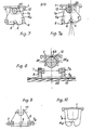
- the invention in addition to the aforementioned means, on the rear face of the mirror support member protrude two parallel arms between which is engaged a cylindrical boss integral with the shaft, these arms s extending between two arms of the spider contiguous to two lateral walls of the base, the invention residing concomitantly in that the shaft of the cylindrical boss is supported by clip-on bearings of the arms of the spider and of the pins of the spider extending along the axis (XX1) parallel to this shaft are supported by clip-on bearings of the side walls of the base, while said cylindrical boss bears against a cylindrical surface of the base concentric with the axis (XX1).
- pins of the spider extending along the axis (YY1) are supported by clip-on bearings formed in tabs projecting from the rear face of the mirror support member.
- the cylindrical boss has at its two ends a hemispherical part which is in contact with a semi-cylindrical surface of the arms provided on the rear face of the mirror support, these arms having notches in which moves the shaft integral with the boss.
- the shaft is coaxial with the boss and has at one of its ends, at least one pinion which meshes with a toothed sector formed on one of the side walls. of the base, and according to a second embodiment, the axis of the boss is eccentric relative to the axis of the shaft and the boss is engaged between two parallel wings extending perpendicularly to the surface of the base .
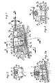
- FIGs 1, 2 and 3 there is shown an embodiment of a device for controlling a rear-view mirror actuated from an operating cable moving in rotation along the double arrow A1, A2 and in following translation the double arrow B1, B2.
- the device comprises a base 1 which comprises lugs 2, 2a provided with holes 3, 3a (Fig. 5.) In which are engaged fixing members for mounting the base on the bottom of a housing not shown in the drawing.
- the spider 6 comprises two cylindrical pins 7, 7a which are pivotally mounted in bearings 8, 8a clipable arranged respectively in tabs 9, 9a (fig. 3) provided on the face rear of a support member 10 of a mirror 22 of rear view mirror.
- This arrangement makes it possible to mount the mirror 22 on the base 1 so that said mirror is capable of moving around a horizontal axis XX1 and a vertical axis YY1.
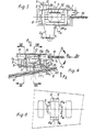
- a cylindrical boss 12 which has at its two ends hemispherical parts 13, 13a which are in contact with semi-cylindrical surfaces 14, 14a (Fig. 6) provided on the arms 11, 11 a.
- the cylindrical boss 12 which is integral with a two-part shaft 15, 15a whose axis is parallel to the axis XX1, and coaxial with the boss is kept in contact with a cylindrical surface 16 formed on the bottom of the base 1.
- the two parts 15, 15a of the shaft are mounted to rotate and slide axially in clip-on bearings 17, 17a formed in arms 6a, 6b, of the spider 6, and the arms 11, 11 a respectively have notches 18, 18a in which are engaged the parts 15, 15a of the shaft integral with the boss 12.
- an operating cable 19 actuated in rotation along the double arrow A1, A2 and in translation along the double arrow B1, B2.
- the other part 15 of the shaft is extended by a pinion 20 which meshes with a toothed sector 21 (FIG. 2) formed in one of the side walls 1a of the base 1.
- control device shown in Figures 1, 2 and 3 operates as follows.
- This pivoting allows a sky-earth movement of the mirror following a rotation of the cable according to the arrow A1, A2 (Fig. 3).
- the boss 12 which bears against the surface 23 of the base 1 is engaged between two parallel wings 24, 24 a (Fig. 4, 5 and 6) extending perpendicular to the surface of the base 1 .
- the mirror 22 being integral with the spider 6, it moves in a sky-earth movement.
Landscapes
- Engineering & Computer Science (AREA)
- General Engineering & Computer Science (AREA)
- Mechanical Engineering (AREA)
- Health & Medical Sciences (AREA)
- Oral & Maxillofacial Surgery (AREA)
- Multimedia (AREA)
- Rear-View Mirror Devices That Are Mounted On The Exterior Of The Vehicle (AREA)
- Optical Elements Other Than Lenses (AREA)
Claims (7)
Applications Claiming Priority (2)
| Application Number | Priority Date | Filing Date | Title |
|---|---|---|---|
| FR8311758A FR2548985B1 (fr) | 1983-07-13 | 1983-07-13 | Dispositif de commande d'un miroir de retroviseur exterieur de l'interieur d'un vehicule |
| FR8311758 | 1983-07-13 |
Publications (2)
| Publication Number | Publication Date |
|---|---|
| EP0132171A1 EP0132171A1 (de) | 1985-01-23 |
| EP0132171B1 true EP0132171B1 (de) | 1987-04-08 |
Family
ID=9290838
Family Applications (1)
| Application Number | Title | Priority Date | Filing Date |
|---|---|---|---|
| EP84401233A Expired EP0132171B1 (de) | 1983-07-13 | 1984-06-15 | Vorrichtung zum Verstellen eines Aussenrückspiegels aus dem Farhzeuginnern |
Country Status (7)
| Country | Link |
|---|---|
| US (1) | US4577823A (de) |
| EP (1) | EP0132171B1 (de) |
| JP (1) | JPS6025826A (de) |
| BR (1) | BR8403329A (de) |
| DE (1) | DE3463019D1 (de) |
| ES (1) | ES289214Y (de) |
| FR (1) | FR2548985B1 (de) |
Families Citing this family (3)
| Publication number | Priority date | Publication date | Assignee | Title |
|---|---|---|---|---|
| DE3577533D1 (de) * | 1985-07-30 | 1990-06-13 | Hohe Kg | Fahrzeug-aussenspiegel mit mechanisch verstellbarem spiegel. |
| ES2005381A6 (es) * | 1987-10-07 | 1989-03-01 | Hohe Iberica | Espejo retrovisor regulable a distancia. |
| GB9413388D0 (en) * | 1994-07-02 | 1994-08-24 | Rover Group | A vehicle locking system |
Family Cites Families (11)
| Publication number | Priority date | Publication date | Assignee | Title |
|---|---|---|---|---|
| US27172A (en) * | 1860-02-14 | Improvement in hand seed-planters | ||
| US2504387A (en) * | 1949-02-12 | 1950-04-18 | Charles A Brady Jr | Rearview mirror having preset selective adjusting means |
| US2684798A (en) * | 1950-07-22 | 1954-07-27 | Schweiter Ltd | Device on an automatic pirn winder for depositing on a pirn skewer board the pirns ejected by an automatic pirn winder |
| US3251238A (en) * | 1963-10-04 | 1966-05-17 | Gen Motors Corp | Remotely controlled rear view mirror |
| US3390588A (en) * | 1966-02-10 | 1968-07-02 | Metalac Corp | Remote control mirror |
| US3628862A (en) * | 1969-08-25 | 1971-12-21 | Allied Chem | Power actuated rearview mirror |
| USRE27172E (en) | 1970-02-27 | 1971-09-20 | Van noord | |
| FR2456641A1 (fr) * | 1979-05-16 | 1980-12-12 | Manzoni Stephane | Dispositif de commande d'un retroviseur exterieur de l'interieur d'un vehicule |
| US4286841A (en) * | 1979-09-06 | 1981-09-01 | Keeler Corporation | Electrically operated remote control rearview mirror |
| US4461190A (en) * | 1981-11-30 | 1984-07-24 | Lacks Industries, Inc. | Gear operated remote control mirror and operative control |
| US4444466A (en) * | 1982-01-28 | 1984-04-24 | Keeler Corporation | Universal joint seal and vibration damper for remotely actuated pivotal devices |
-
1983
- 1983-07-13 FR FR8311758A patent/FR2548985B1/fr not_active Expired
-
1984
- 1984-06-15 EP EP84401233A patent/EP0132171B1/de not_active Expired
- 1984-06-15 DE DE8484401233T patent/DE3463019D1/de not_active Expired
- 1984-06-27 JP JP59131190A patent/JPS6025826A/ja active Pending
- 1984-07-04 BR BR8403329A patent/BR8403329A/pt unknown
- 1984-07-10 ES ES1984289214U patent/ES289214Y/es not_active Expired
- 1984-07-13 US US06/630,780 patent/US4577823A/en not_active Expired - Fee Related
Also Published As
| Publication number | Publication date |
|---|---|
| FR2548985A1 (fr) | 1985-01-18 |
| US4577823A (en) | 1986-03-25 |
| ES289214U (es) | 1986-02-16 |
| BR8403329A (pt) | 1985-06-18 |
| FR2548985B1 (fr) | 1985-10-25 |
| EP0132171A1 (de) | 1985-01-23 |
| DE3463019D1 (en) | 1987-05-14 |
| JPS6025826A (ja) | 1985-02-08 |
| ES289214Y (es) | 1986-10-01 |
Similar Documents
| Publication | Publication Date | Title |
|---|---|---|
| EP0179002B1 (de) | Einrichtung zum automatischen Schliessen, sowie zum Offenhalten von Türen | |
| EP3404177B1 (de) | Steuermechanismus eines flächenbündigen griffs | |
| EP3404176B1 (de) | Vorrichtung zum entriegeln eines türschlosses | |
| EP0094856B1 (de) | Kuppelbegrenzungsvorrichtung zum Betätigen eines Rückspiegels | |
| EP0064421B1 (de) | Ferngesteuerte Einrichtung für einen Fahrzeugrückblickspiegel | |
| EP0459867A1 (de) | Gelenkverbindung zwischen einem Scheibenwischerarm und einem Scheibenwischerblatt | |
| EP0132171B1 (de) | Vorrichtung zum Verstellen eines Aussenrückspiegels aus dem Farhzeuginnern | |
| EP1470012B1 (de) | Kofferraumdeckel für ein cabriofahrzeug mit faltverdeck | |
| EP0019501B1 (de) | Vorrichtung zum Steuern eines Aussenrückspiegels vom Innern eines Fahrzeuges | |
| EP0163583B1 (de) | Montagevorrichtung, insbesondere vom Gelenk des Spannarmes der Kettenführung der Gangschaltung für Fahrräder oder ähnliche Fahrzeuge | |
| EP1106774B1 (de) | Vorrichtung zum Fixieren eines Antriebs, und Betätigungsmechanismus einer Schliess- oder Sonnenschutzeinrichtung mit solcher Vorrichtung | |
| FR2471887A1 (fr) | Dispositif de relevage pouvant etre actionne electriquement pour un retroviseur de vehicule automobile | |
| EP1059409A1 (de) | Antriebsgetriebe für Schlossnuss | |
| EP0064422B1 (de) | Ferngesteuerte Einrichtung für einen Fahrzeugrückblickspiegel | |
| FR2769037A1 (fr) | Dispositif de verrouillage comportant un doigt de transmission commande par came | |
| EP0007851A1 (de) | Antriebsvorrichtung für eine verschiebbare Scheibe eines Kraftfahrzeuges, insbesondere Fensterheber für eine Wagentür | |
| FR3107295A1 (fr) | Dispositif de verrouillage pour une pièce mobile d’un véhicule | |
| EP0531216A1 (de) | Türscharnier mit integriertem Türfeststeller, insbesondere für eine Fahrzeugtür | |
| EP0023448B1 (de) | Schloss mit entkuppelbarem Bedienungsdorn | |
| EP1637676A2 (de) | Türgriff und Verfahren zur Montage desgleichen | |
| EP0078758B1 (de) | Momentreduktionsgetriebe | |
| FR2552508A1 (fr) | Perfectionnement a un dispositif d'ajustement automatique pour un embrayage a friction | |
| FR2539451A2 (fr) | Dispositif d'entrainement pour panneau coulissant de vehicule automobile | |
| FR2851975A1 (fr) | Mecanisme d'essuyage comportant des moyens de blocage de l'arbre d'entrainement dans une position angulaire | |
| FR2818686A1 (fr) | Dispositif d'immobilisation d'un organe d'entrainement et mecanisme de manoeuvre d'une installation de fermeture ou de protection solaire comprenant un tel dispositif |
Legal Events
| Date | Code | Title | Description |
|---|---|---|---|
| PUAI | Public reference made under article 153(3) epc to a published international application that has entered the european phase |
Free format text: ORIGINAL CODE: 0009012 |
|
| AK | Designated contracting states |
Designated state(s): DE GB IT SE |
|
| 17P | Request for examination filed |
Effective date: 19841224 |
|
| GRAA | (expected) grant |
Free format text: ORIGINAL CODE: 0009210 |
|
| AK | Designated contracting states |
Kind code of ref document: B1 Designated state(s): DE GB IT SE |
|
| REF | Corresponds to: |
Ref document number: 3463019 Country of ref document: DE Date of ref document: 19870514 |
|
| RAP2 | Party data changed (patent owner data changed or rights of a patent transferred) |
Owner name: MANZONI-BOUCHOT SOCIETE ANONYME DITE: |
|
| RIN2 | Information on inventor provided after grant (corrected) |
Free format text: MANZONI, STEPHANE |
|
| ITF | It: translation for a ep patent filed | ||
| RAP2 | Party data changed (patent owner data changed or rights of a patent transferred) |
Owner name: SOCIETE MANZONI BOUCHOT |
|
| PLBE | No opposition filed within time limit |
Free format text: ORIGINAL CODE: 0009261 |
|
| STAA | Information on the status of an ep patent application or granted ep patent |
Free format text: STATUS: NO OPPOSITION FILED WITHIN TIME LIMIT |
|
| 26N | No opposition filed | ||
| PG25 | Lapsed in a contracting state [announced via postgrant information from national office to epo] |
Ref country code: GB Effective date: 19880615 |
|
| PG25 | Lapsed in a contracting state [announced via postgrant information from national office to epo] |
Ref country code: SE Effective date: 19880616 |
|
| GBPC | Gb: european patent ceased through non-payment of renewal fee | ||
| PG25 | Lapsed in a contracting state [announced via postgrant information from national office to epo] |
Ref country code: DE Effective date: 19890301 |
|
| EUG | Se: european patent has lapsed |
Ref document number: 84401233.6 Effective date: 19890220 |