EP0132174A1 - Vorrichtung zur Reinigung von Gasen, wie Luft, verunreinigt mit ölartigen oder hydroxycarbonierten flüssigen in diesem Gas dispergierten Komponenten - Google Patents
Vorrichtung zur Reinigung von Gasen, wie Luft, verunreinigt mit ölartigen oder hydroxycarbonierten flüssigen in diesem Gas dispergierten Komponenten Download PDFInfo
- Publication number
- EP0132174A1 EP0132174A1 EP84401265A EP84401265A EP0132174A1 EP 0132174 A1 EP0132174 A1 EP 0132174A1 EP 84401265 A EP84401265 A EP 84401265A EP 84401265 A EP84401265 A EP 84401265A EP 0132174 A1 EP0132174 A1 EP 0132174A1
- Authority
- EP
- European Patent Office
- Prior art keywords
- gas
- separation device
- oily
- purification chamber
- compounds
- Prior art date
- Legal status (The legal status is an assumption and is not a legal conclusion. Google has not performed a legal analysis and makes no representation as to the accuracy of the status listed.)
- Granted
Links
- 239000007788 liquid Substances 0.000 title claims abstract description 11
- 239000007789 gas Substances 0.000 claims abstract description 56
- 238000000746 purification Methods 0.000 claims abstract description 45
- 238000000926 separation method Methods 0.000 claims abstract description 43
- 150000002430 hydrocarbons Chemical class 0.000 claims abstract description 33
- 150000001875 compounds Chemical class 0.000 claims abstract description 17
- 229930195733 hydrocarbon Natural products 0.000 claims abstract description 15
- 230000005484 gravity Effects 0.000 claims abstract description 6
- 238000004581 coalescence Methods 0.000 claims abstract description 5
- 239000004743 Polypropylene Substances 0.000 claims abstract description 4
- 239000000463 material Substances 0.000 claims abstract description 4
- -1 polypropylene Polymers 0.000 claims abstract description 4
- 229920001155 polypropylene Polymers 0.000 claims abstract description 4
- 238000011144 upstream manufacturing Methods 0.000 claims abstract description 4
- 239000004744 fabric Substances 0.000 claims abstract description 3
- 239000004215 Carbon black (E152) Substances 0.000 claims description 11
- 238000005192 partition Methods 0.000 claims description 9
- 238000004094 preconcentration Methods 0.000 claims description 7
- 239000011261 inert gas Substances 0.000 claims description 4
- 238000009413 insulation Methods 0.000 claims description 4
- 239000003507 refrigerant Substances 0.000 claims description 4
- 230000000717 retained effect Effects 0.000 claims description 4
- 239000003599 detergent Substances 0.000 claims description 3
- 238000010438 heat treatment Methods 0.000 claims description 3
- 239000002904 solvent Substances 0.000 claims description 3
- 238000005507 spraying Methods 0.000 claims description 3
- 239000003595 mist Substances 0.000 abstract description 2
- 238000001914 filtration Methods 0.000 abstract 1
- CURLTUGMZLYLDI-UHFFFAOYSA-N Carbon dioxide Chemical compound O=C=O CURLTUGMZLYLDI-UHFFFAOYSA-N 0.000 description 2
- 238000002955 isolation Methods 0.000 description 2
- 239000003921 oil Substances 0.000 description 2
- 229910002092 carbon dioxide Inorganic materials 0.000 description 1
- 239000001569 carbon dioxide Substances 0.000 description 1
- 238000001816 cooling Methods 0.000 description 1
- 239000006185 dispersion Substances 0.000 description 1
- 230000000694 effects Effects 0.000 description 1
- 230000007613 environmental effect Effects 0.000 description 1
- 238000001704 evaporation Methods 0.000 description 1
- 230000008020 evaporation Effects 0.000 description 1
- 238000000605 extraction Methods 0.000 description 1
- 239000012530 fluid Substances 0.000 description 1
- 229910052736 halogen Inorganic materials 0.000 description 1
- 150000002367 halogens Chemical class 0.000 description 1
- 238000003754 machining Methods 0.000 description 1
- 238000004519 manufacturing process Methods 0.000 description 1
- 238000000034 method Methods 0.000 description 1
- 239000007921 spray Substances 0.000 description 1
- 238000013517 stratification Methods 0.000 description 1
Images

Classifications
-
- B—PERFORMING OPERATIONS; TRANSPORTING
- B01—PHYSICAL OR CHEMICAL PROCESSES OR APPARATUS IN GENERAL
- B01D—SEPARATION
- B01D50/00—Combinations of methods or devices for separating particles from gases or vapours
- B01D50/20—Combinations of devices covered by groups B01D45/00 and B01D46/00
Definitions
- the present invention essentially relates to an apparatus for purifying gases, such as air contaminated with oily compounds or liquid hydrocarbons dispersed in said gas.
- a device has already been proposed for purifying air contaminated with oily or liquid hydrocarbon compounds dispersed therein.
- Known devices comprise a box provided with an air supply conduit containing the oily or hydrocarbon compound, opening into a purification chamber and an air outlet conduit, said purification chamber comprising a device for separating the compounds oily or hydrocarbon disposed perpendicularly or obliquely to the passage of air from the supply duct to the outlet duct; and a reservoir for collecting oily or hydrocarbon compounds, placed under the separation device so as to collect the compounds retained by the separation device, and falling by gravity.
- the separation is very poor and the air leaving through the outlet conduit still contains a non-negligible percentage of oily or liquid hydrocarbon compounds dispersed in the air, which is unacceptable.
- the present invention therefore aims to solve the technical problem constituted by the effective purification of air, and more generally of gas, contaminated with oily or liquid hydrocarbon compounds dispersed therein.
- the present invention provides for the first time a solution to this technical problem.
- the invention therefore relates to an apparatus for purifying gases, such as air, contaminated with oily or liquid hydrocarbon compounds dispersed in said gas, of the type mentioned above, that is to say comprising a box provided with at least one gas supply conduit containing the oily or hydrocarbon compounds, opening into a purification chamber, and at least one outlet for the purified gas from said chamber, said purification chamber comprising a device for separating the compounds oily or hydrocarbon-based, disposed in the passage of air from the supply duct to the outlet duct, a collection tank for oily or hydrocarbon-based compounds, placed under the separation device so as to collect said retained oily or hydrocarbon-based compounds by said separation device and falling by gravity, characterized, according to the invention, in that the separation device is arranged substantially horizontally and in that the core duct born of gas to be purified opens laterally into said chamber, and preferably substantially parallel to the general plane of said separation device.
- the purification chamber also comprises a device for dynamic preconcentration of the dispersed compounds, arranged upstream of the separation device.
- the preconcentration device comprises a wall arranged so as to form an obstacle relative to the current of gas introduced into the purification chamber. And thus deflect it before it passes through the separation device.
- this obstacle wall is disposed substantially vertically and forms a partition separating the purification chamber into two compartments, said partition being shorter than the height of said purification chamber and leaving a free space downward for the passage of gas, said partition preferably serving for fixing one end of the aforementioned separation device arranged in the compartment in downstream or out of the purification chamber.
- the apparatus comprises downstream of the aforementioned separation device, an additional filter made of a hydrocarbon-hungry material, preferably polypropylene, also arranged horizontally.
- an additional filter made of a hydrocarbon-hungry material, preferably polypropylene, also arranged horizontally.
- the apparatus comprises, downstream of the above-mentioned separation device, a system for rinsing the separation device, preferably by spraying with a suitable product, such as detergent or solvent.
- a suitable product such as detergent or solvent.
- the apparatus according to the invention in the case of a relatively hot gas, such as room or local air, is preferably also characterized in that, towards the outlet of the purification chamber, is arranged a heat exchanger recovering the calories from the gas leaving said purification chamber, by heating a refrigerant which is then advantageously used to heat the gas introduced into said room or room which, in the case where the gas is other than air, can be a reactor.
- a relatively hot gas such as room or local air
- the device according to the invention advantageously comprises a sealed insulation system of the purification chamber vis-à-vis the room or the room, which, according to a way preferred embodiment may include movable flaps arranged in the access and outlet conduits, capable of closing said conduits, as well as means for introducing inert gas into said purification chamber, avoiding any risk of fire.
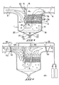
- an apparatus for purifying gas such as air, contaminated by oily compounds or liquid hydrocarbons dispersed therein, comprises a box 1 provided with at least one gas supply conduit 2 containing the oily or hydrocarbon compounds, opening into a purification chamber 4 and at least one conduit 6 for leaving the purified gas, said purification chamber 4 comprising a device 8 for separating oily or hydrocarbon compounds, arranged in the passage of the gas symbolized by the arrows, from the supply pipe 2 towards the outlet pipe 6, and a tank 10 for collecting the oily or hydrocarbon compounds 12, so as to collect said compounds retained by the separation device 8 and falling by gravity, as symbolized by the drops 14.
- This device is according to the invention characterized in that the separation device 8 is disposed substantially horizontally and in that the conduit 2 for supplying gas to be purified opens laterally into the purifying chamber 4, and preferably substantially parallel to the general plan of the separation device 8, as shown in FIG. 1.
- the purification chamber 10 comprises a device 16 for dynamic preconcentration of the dispersed compounds, arranged upstream of the separation device 8.
- this preconcentration device 16 comprises a wall 18 arranged so as to form an obstacle relative to the gas stream introduced into the purification chamber 4 and thus to deflect said gas before it passes through the separation device 8, as clearly understood from FIG. 1.
- this wall 18 forming an obstacle is disposed substantially vertically and forms a partition separating the purification chamber 4 in two. compartments 4a; 4b; said partition 18 being shorter than the height of said purification chamber 4 and leaving a free space 20 downwards for the passage of gas as is clearly visible in FIG. 1.
- the partition 18 is used for fixing an end 8a of the separation device 8.
- the obstacle-forming wall 18 is provided with baffles 22 or the like over its entire surface, or the majority thereof, arranged in spaced relation relative to said obstacle-forming wall 18.
- the baffles 22 are used for a first coalescence of the vesicles of oily or hydrocarbon products dispersed in the gas, preferably consisting of air, into droplets 24 which also fall by gravity; said baffles 22 also serving to avoid redispersion of the droplets 24 in the gas.
- the collection tank for oily or hydrocarbon compounds can have various forms.
- the collection tank 10 is formed by the lower part of the purification chamber 4, preferably shaped like a funnel 26, the bottom 28 of which comprises an opening 30 closed by a valve 32 which is open at will to evacuate the oily or hydrocarbon compounds 12 collected in said tank 10.
- a grid 34 is arranged at the bottom of the purification chamber 4 so as to produce a physical separation between the purification chamber 4 proper and the collection tank 10.
- the separation device 8 is a filter for separation by coalescence of the vesicles of oily or hydrocarbon products in droplets and is preferably constituted by a plurality of layers of tissue, in particular metallic , advantageously very thick.
- the apparatus according to the invention further comprises downstream of the separation device 8, at least one filter additional 34 made of a hydrocarbon-hungry material, preferably polypropylene, also arranged horizontally and which traps the last vesicles of oily or hydrocarbon compounds dispersed in the gas.
- a hydrocarbon-hungry material preferably polypropylene
- the apparatus preferably comprises, downstream of the separation device 8, a rinsing system 38 of the separation device 8, preferably by spraying, for example using a spray bar, as shown, with a suitable product 40 such as a detergent or solvent as the case may be.
- the apparatus according to the invention is preferably provided, towards the outlet of the purification chamber 4, with a heat exchanger 42 recovering the calories from the gas leaving said chamber 4, by heating a refrigerant which is then advantageously used to heat the gas introduced into said room or room by the presence of another heat exchanger 44, shown in FIG. 3.
- the room or room 46 may include several purification devices 1 according to the invention, each of which is provided on the outlet pipe 6 with a heat exchanger 42 forming part of a circuit closed 48 comprising a heat exchanger 44 in order to preheat here the air 50 entering the room 46 and located at a lower temperature.
- a heat exchanger 42 forming part of a circuit closed 48 comprising a heat exchanger 44 in order to preheat here the air 50 entering the room 46 and located at a lower temperature.
- the same principle also applies in the opposite case.
- the apparatus according to invention includes a sealed insulation system 60 of the chamber 4 of the room 46.
- this isolation system 60 comprises movable flaps 62, 64 arranged in the access and outlet conduits 6 capable of closing said conduits 2, 6, as shown in FIG. 2 by control by hydraulic, pneumatic, electric, or electromagnetic means customary in the art and which will be apparent to those skilled in the art, shown diagrammatically by reference number 66, and by preferably combined with means 68 for introducing inert gas into said purification chamber 4, avoiding any risk of fire.
- inert gas there may be mentioned for example carbon dioxide, halogens, etc. Such gases will also be apparent to a person skilled in the art.
- any other device of the technique For example, we can introduce a heat pump in circuit 48 of figure 3 or even use a device for varying the flow of gas sucked into the purification chamber represented by the reference number 70, figure 4, like the device marketed by the plaintiff under the trade name Variflow.
- the preconcentration device 16 can comprise, instead of the baffles 22, a grid 72 (FIG. 4) arranged obliquely in the compartment 4a of the purification chamber 4.
- the invention therefore includes all the means constituting technical equivalents of the means described as well as their various combinations.
Landscapes
- Chemical & Material Sciences (AREA)
- Chemical Kinetics & Catalysis (AREA)
- Gas Separation By Absorption (AREA)
- Treating Waste Gases (AREA)
- Air-Conditioning For Vehicles (AREA)
- Separation By Low-Temperature Treatments (AREA)
- Pharmaceuticals Containing Other Organic And Inorganic Compounds (AREA)
Priority Applications (1)
| Application Number | Priority Date | Filing Date | Title |
|---|---|---|---|
| AT84401265T ATE37667T1 (de) | 1983-06-29 | 1984-06-19 | Vorrichtung zur reinigung von gasen, wie luft, verunreinigt mit oelartigen oder hydroxycarbonierten fluessigen in diesem gas dispergierten komponenten. |
Applications Claiming Priority (2)
| Application Number | Priority Date | Filing Date | Title |
|---|---|---|---|
| FR8310781 | 1983-06-29 | ||
| FR8310781A FR2548041B1 (fr) | 1983-06-29 | 1983-06-29 | Appareil d'epuration de gaz, tel que l'air, contamine par des composes huileux ou hydrocarbones liquides disperses dans ledit gaz |
Publications (2)
| Publication Number | Publication Date |
|---|---|
| EP0132174A1 true EP0132174A1 (de) | 1985-01-23 |
| EP0132174B1 EP0132174B1 (de) | 1988-10-05 |
Family
ID=9290308
Family Applications (1)
| Application Number | Title | Priority Date | Filing Date |
|---|---|---|---|
| EP84401265A Expired EP0132174B1 (de) | 1983-06-29 | 1984-06-19 | Vorrichtung zur Reinigung von Gasen, wie Luft, verunreinigt mit ölartigen oder hydroxycarbonierten flüssigen in diesem Gas dispergierten Komponenten |
Country Status (7)
| Country | Link |
|---|---|
| EP (1) | EP0132174B1 (de) |
| AT (1) | ATE37667T1 (de) |
| DE (1) | DE3474415D1 (de) |
| DK (1) | DK163866C (de) |
| FI (1) | FI80613C (de) |
| FR (1) | FR2548041B1 (de) |
| NO (1) | NO163316C (de) |
Cited By (7)
| Publication number | Priority date | Publication date | Assignee | Title |
|---|---|---|---|---|
| EP0443258A1 (de) * | 1990-02-23 | 1991-08-28 | Thermo King Corporation | Ölabscheider für Kühlgerät |
| EP1068890A1 (de) * | 1999-07-16 | 2001-01-17 | Nelson Industries, Inc. | Gas-Flüssigkeit Trägheits-Abscheider |
| EP1106229A1 (de) * | 1999-12-03 | 2001-06-13 | Frigomec S.r.l. | Ölabscheider |
| CN103057930A (zh) * | 2013-01-06 | 2013-04-24 | 昆明凌杰商贸有限公司 | 无耗能除尘系统 |
| US9027591B2 (en) | 2009-10-21 | 2015-05-12 | Victor Equipment Company | Gas pressure regulator with particle trap and diffuser |
| CN108970262A (zh) * | 2018-08-03 | 2018-12-11 | 蚌埠市昊源压缩机制造有限公司 | 一种防止bog压缩机入口过滤器堵塞的方法 |
| CN109058070A (zh) * | 2018-08-03 | 2018-12-21 | 蚌埠市昊源压缩机制造有限公司 | 一种方便清理过滤器的bog压缩机 |
Families Citing this family (1)
| Publication number | Priority date | Publication date | Assignee | Title |
|---|---|---|---|---|
| GB9000793D0 (en) * | 1990-01-13 | 1990-03-14 | Kelburn Engineering Company Lt | Gas/liquid separator |
Citations (3)
| Publication number | Priority date | Publication date | Assignee | Title |
|---|---|---|---|---|
| BE519925A (de) * | ||||
| US3856487A (en) * | 1972-08-11 | 1974-12-24 | Aerosols Control Corp | Gas scrubber |
| FR2401690A1 (fr) * | 1977-08-31 | 1979-03-30 | Bahco Ventilation Ab | Filtre a gaz avec dispositif de captage des poussieres |
-
1983
- 1983-06-29 FR FR8310781A patent/FR2548041B1/fr not_active Expired
-
1984
- 1984-06-19 AT AT84401265T patent/ATE37667T1/de not_active IP Right Cessation
- 1984-06-19 EP EP84401265A patent/EP0132174B1/de not_active Expired
- 1984-06-19 DE DE8484401265T patent/DE3474415D1/de not_active Expired
- 1984-06-26 FI FI842563A patent/FI80613C/fi not_active IP Right Cessation
- 1984-06-28 DK DK316584A patent/DK163866C/da not_active IP Right Cessation
- 1984-06-28 NO NO842624A patent/NO163316C/no not_active IP Right Cessation
Patent Citations (3)
| Publication number | Priority date | Publication date | Assignee | Title |
|---|---|---|---|---|
| BE519925A (de) * | ||||
| US3856487A (en) * | 1972-08-11 | 1974-12-24 | Aerosols Control Corp | Gas scrubber |
| FR2401690A1 (fr) * | 1977-08-31 | 1979-03-30 | Bahco Ventilation Ab | Filtre a gaz avec dispositif de captage des poussieres |
Cited By (9)
| Publication number | Priority date | Publication date | Assignee | Title |
|---|---|---|---|---|
| EP0443258A1 (de) * | 1990-02-23 | 1991-08-28 | Thermo King Corporation | Ölabscheider für Kühlgerät |
| EP1068890A1 (de) * | 1999-07-16 | 2001-01-17 | Nelson Industries, Inc. | Gas-Flüssigkeit Trägheits-Abscheider |
| US6290738B1 (en) | 1999-07-16 | 2001-09-18 | Nelson Industries, Inc. | Inertial gas-liquid separator having an inertial collector spaced from a nozzle structure |
| EP1106229A1 (de) * | 1999-12-03 | 2001-06-13 | Frigomec S.r.l. | Ölabscheider |
| US9027591B2 (en) | 2009-10-21 | 2015-05-12 | Victor Equipment Company | Gas pressure regulator with particle trap and diffuser |
| CN103057930A (zh) * | 2013-01-06 | 2013-04-24 | 昆明凌杰商贸有限公司 | 无耗能除尘系统 |
| CN103057930B (zh) * | 2013-01-06 | 2014-11-12 | 昆明凌杰商贸有限公司 | 无耗能除尘系统 |
| CN108970262A (zh) * | 2018-08-03 | 2018-12-11 | 蚌埠市昊源压缩机制造有限公司 | 一种防止bog压缩机入口过滤器堵塞的方法 |
| CN109058070A (zh) * | 2018-08-03 | 2018-12-21 | 蚌埠市昊源压缩机制造有限公司 | 一种方便清理过滤器的bog压缩机 |
Also Published As
| Publication number | Publication date |
|---|---|
| DK163866B (da) | 1992-04-13 |
| NO163316B (no) | 1990-01-29 |
| EP0132174B1 (de) | 1988-10-05 |
| NO842624L (no) | 1985-01-02 |
| FI842563A0 (fi) | 1984-06-26 |
| FI80613C (fi) | 1990-07-10 |
| NO163316C (no) | 1990-05-09 |
| DE3474415D1 (en) | 1988-11-10 |
| DK316584A (da) | 1984-12-30 |
| FI80613B (fi) | 1990-03-30 |
| FR2548041B1 (fr) | 1988-01-15 |
| DK316584D0 (da) | 1984-06-28 |
| FR2548041A1 (fr) | 1985-01-04 |
| FI842563A7 (fi) | 1984-12-30 |
| ATE37667T1 (de) | 1988-10-15 |
| DK163866C (da) | 1992-09-21 |
Similar Documents
| Publication | Publication Date | Title |
|---|---|---|
| BE1005258A5 (fr) | Installation de purification d'air d'echappement. | |
| US6022389A (en) | System for removal of noxious fumes | |
| US4409950A (en) | Fuel saver and pollution control device | |
| US6517594B2 (en) | Air management system and method for chemical containment and contamination reduction in a semiconductor manufacturing facility | |
| US4084947A (en) | Filter apparatus for fast food kitchens exhaust | |
| US5549128A (en) | General parts washer | |
| FR2548041A1 (fr) | Appareil d'epuration de gaz, tel que l'air, contamine par des composes huileux ou hydrocarbones liquides disperses dans ledit gaz | |
| US4289586A (en) | Solvent recovery method | |
| US6032462A (en) | Apparatus for cleaning vehicle exhaust gases | |
| US4846967A (en) | Apparatus for reclaiming contaminated oil | |
| US4692251A (en) | Solvent cleansing apparatus | |
| US5518013A (en) | Immersion washer apparatus | |
| US4869831A (en) | Separating immiscible components from toxic fluid | |
| US4770197A (en) | Apparatus for recovering solvent | |
| WO2000020137A1 (en) | Vapor containment and recovery system on a general parts washer apparatus | |
| US4707878A (en) | Vacuum loading cleaning system | |
| FR3065787A3 (fr) | Hote d'aspiration pour laboratoire | |
| US5213594A (en) | Controlling solvent vapors in dry cleaning apparatus | |
| US5360371A (en) | Material handling apparatus and method | |
| EP0333607A1 (de) | Vorrichtung zur dynamischen Begrenzung | |
| US4190014A (en) | Industrial dust collector cleaning system and method | |
| US4881511A (en) | Crankcase ventilator | |
| US5194185A (en) | Atomization of condensate water | |
| US4666597A (en) | Fuel treatment apparatus | |
| JP2010053762A (ja) | エンジン駆動型作業機のブローバイガス分離排出装置 |
Legal Events
| Date | Code | Title | Description |
|---|---|---|---|
| PUAI | Public reference made under article 153(3) epc to a published international application that has entered the european phase |
Free format text: ORIGINAL CODE: 0009012 |
|
| AK | Designated contracting states |
Designated state(s): AT BE CH DE GB IT LI LU NL SE |
|
| 17P | Request for examination filed |
Effective date: 19850704 |
|
| GRAA | (expected) grant |
Free format text: ORIGINAL CODE: 0009210 |
|
| AK | Designated contracting states |
Kind code of ref document: B1 Designated state(s): AT BE CH DE GB IT LI LU NL SE |
|
| PG25 | Lapsed in a contracting state [announced via postgrant information from national office to epo] |
Ref country code: SE Effective date: 19881005 Ref country code: NL Effective date: 19881005 Ref country code: IT Free format text: LAPSE BECAUSE OF FAILURE TO SUBMIT A TRANSLATION OF THE DESCRIPTION OR TO PAY THE FEE WITHIN THE PRESCRIBED TIME-LIMIT;WARNING: LAPSES OF ITALIAN PATENTS WITH EFFECTIVE DATE BEFORE 2007 MAY HAVE OCCURRED AT ANY TIME BEFORE 2007. THE CORRECT EFFECTIVE DATE MAY BE DIFFERENT FROM THE ONE RECORDED. Effective date: 19881005 Ref country code: AT Effective date: 19881005 |
|
| REF | Corresponds to: |
Ref document number: 37667 Country of ref document: AT Date of ref document: 19881015 Kind code of ref document: T |
|
| REF | Corresponds to: |
Ref document number: 3474415 Country of ref document: DE Date of ref document: 19881110 |
|
| GBT | Gb: translation of ep patent filed (gb section 77(6)(a)/1977) | ||
| NLV1 | Nl: lapsed or annulled due to failure to fulfill the requirements of art. 29p and 29m of the patents act | ||
| PG25 | Lapsed in a contracting state [announced via postgrant information from national office to epo] |
Ref country code: LU Free format text: LAPSE BECAUSE OF NON-PAYMENT OF DUE FEES Effective date: 19890630 Ref country code: LI Effective date: 19890630 Ref country code: CH Effective date: 19890630 |
|
| PLBE | No opposition filed within time limit |
Free format text: ORIGINAL CODE: 0009261 |
|
| STAA | Information on the status of an ep patent application or granted ep patent |
Free format text: STATUS: NO OPPOSITION FILED WITHIN TIME LIMIT |
|
| 26N | No opposition filed | ||
| REG | Reference to a national code |
Ref country code: CH Ref legal event code: PL |
|
| PGFP | Annual fee paid to national office [announced via postgrant information from national office to epo] |
Ref country code: DE Payment date: 20010611 Year of fee payment: 18 |
|
| PGFP | Annual fee paid to national office [announced via postgrant information from national office to epo] |
Ref country code: GB Payment date: 20010613 Year of fee payment: 18 |
|
| PGFP | Annual fee paid to national office [announced via postgrant information from national office to epo] |
Ref country code: BE Payment date: 20010816 Year of fee payment: 18 |
|
| REG | Reference to a national code |
Ref country code: GB Ref legal event code: IF02 |
|
| PG25 | Lapsed in a contracting state [announced via postgrant information from national office to epo] |
Ref country code: GB Free format text: LAPSE BECAUSE OF NON-PAYMENT OF DUE FEES Effective date: 20020619 |
|
| PG25 | Lapsed in a contracting state [announced via postgrant information from national office to epo] |
Ref country code: BE Free format text: LAPSE BECAUSE OF NON-PAYMENT OF DUE FEES Effective date: 20020630 |
|
| BERE | Be: lapsed |
Owner name: *FLAKT A.B. Effective date: 20020630 |
|
| PG25 | Lapsed in a contracting state [announced via postgrant information from national office to epo] |
Ref country code: DE Free format text: LAPSE BECAUSE OF NON-PAYMENT OF DUE FEES Effective date: 20030101 |
|
| GBPC | Gb: european patent ceased through non-payment of renewal fee |
Effective date: 20020619 |