EP0132200A1 - Elektrooptischer Fugen- und Bündigkeitsdetektor - Google Patents
Elektrooptischer Fugen- und Bündigkeitsdetektor Download PDFInfo
- Publication number
- EP0132200A1 EP0132200A1 EP84401474A EP84401474A EP0132200A1 EP 0132200 A1 EP0132200 A1 EP 0132200A1 EP 84401474 A EP84401474 A EP 84401474A EP 84401474 A EP84401474 A EP 84401474A EP 0132200 A1 EP0132200 A1 EP 0132200A1
- Authority
- EP
- European Patent Office
- Prior art keywords
- panel
- gap
- rail
- edge
- image
- Prior art date
- Legal status (The legal status is an assumption and is not a legal conclusion. Google has not performed a legal analysis and makes no representation as to the accuracy of the status listed.)
- Withdrawn
Links
- 238000000034 method Methods 0.000 claims description 13
- 230000008859 change Effects 0.000 claims description 3
- 238000003384 imaging method Methods 0.000 claims description 3
- 230000000712 assembly Effects 0.000 abstract description 3
- 238000000429 assembly Methods 0.000 abstract description 3
- 238000005259 measurement Methods 0.000 description 18
- 238000005286 illumination Methods 0.000 description 7
- 230000000694 effects Effects 0.000 description 4
- 239000000835 fiber Substances 0.000 description 4
- 239000011159 matrix material Substances 0.000 description 4
- 230000003287 optical effect Effects 0.000 description 4
- 230000010354 integration Effects 0.000 description 3
- 239000004033 plastic Substances 0.000 description 3
- 229920003023 plastic Polymers 0.000 description 3
- 238000003491 array Methods 0.000 description 2
- 230000008901 benefit Effects 0.000 description 2
- 238000013461 design Methods 0.000 description 2
- 238000009826 distribution Methods 0.000 description 2
- 230000006870 function Effects 0.000 description 2
- 238000007689 inspection Methods 0.000 description 2
- 238000004519 manufacturing process Methods 0.000 description 2
- 239000000463 material Substances 0.000 description 2
- 230000000284 resting effect Effects 0.000 description 2
- 239000002023 wood Substances 0.000 description 2
- 238000012935 Averaging Methods 0.000 description 1
- 229910000760 Hardened steel Inorganic materials 0.000 description 1
- 230000009471 action Effects 0.000 description 1
- 210000000078 claw Anatomy 0.000 description 1
- 230000007547 defect Effects 0.000 description 1
- 238000010586 diagram Methods 0.000 description 1
- 230000005670 electromagnetic radiation Effects 0.000 description 1
- 239000011152 fibreglass Substances 0.000 description 1
- 230000006872 improvement Effects 0.000 description 1
- 238000003780 insertion Methods 0.000 description 1
- 230000037431 insertion Effects 0.000 description 1
- 238000005304 joining Methods 0.000 description 1
- 238000011326 mechanical measurement Methods 0.000 description 1
- 230000005055 memory storage Effects 0.000 description 1
- 230000004048 modification Effects 0.000 description 1
- 238000012986 modification Methods 0.000 description 1
- 239000013307 optical fiber Substances 0.000 description 1
- 239000003973 paint Substances 0.000 description 1
- 230000008569 process Effects 0.000 description 1
- 238000012545 processing Methods 0.000 description 1
- 238000003672 processing method Methods 0.000 description 1
- 230000005855 radiation Effects 0.000 description 1
- 238000001228 spectrum Methods 0.000 description 1
- 230000007704 transition Effects 0.000 description 1
- 238000003466 welding Methods 0.000 description 1
Images


Classifications
-
- G—PHYSICS
- G01—MEASURING; TESTING
- G01B—MEASURING LENGTH, THICKNESS OR SIMILAR LINEAR DIMENSIONS; MEASURING ANGLES; MEASURING AREAS; MEASURING IRREGULARITIES OF SURFACES OR CONTOURS
- G01B11/00—Measuring arrangements characterised by the use of optical techniques
- G01B11/14—Measuring arrangements characterised by the use of optical techniques for measuring distance or clearance between spaced objects or spaced apertures
Definitions
- the panels In the manufacture of cars it is highly desirable for "customer aesthetic" purposes that the panels, such as doors, for example, when fitted together with the other panels, have a uniform gap falling within a nominal size as one looks along the gap. As well, the panels should be essentially as flush as possible, that is, in the same plane, at their joining edges. This condition is often difficult to achieve in practice and requires rigid statistical controls on the panel production and assembly in order to insure that quality can be maintained. The measurements required for such control occur both at the stamping or plastics facility in which a single panel is compared to a master ring (simulating the fit of the other panels around it) or on the finish welded car "body in white” or even the final assembled and painted car.
- the present invention relates to preferably non-contact sensors for the applications described above more particularly to a hand-held unit that can be used easily by operators in accumulating statistical data. Further embodiments involve other varients which can be used on robots for automated measuring. All of the above disadvantages are obviated by the sensor unit of the invention.
- This reference rail gage is generally placed all the way around the panel (such as the car rear door shown in Figure 1(b)) or could be only over a portion.
- gage rail 1 follows the contour of the panel 2, and forms a "ring", which is used to simulate essentially a master opening in the car body into which the door is to fit.
- the door panel 2 is placed into this and referring to the cross section of Figure l(a), we see that a gap of width "W” and a flushness condition of height "H” exists.
- the distance “H” can either be positive or negative, with a zero “H” or "flush” condition being the desired case.
- a nominal gap of + or - some nominal value eg. 3mm
- + or - 1 millimeter e.g. 3mm
- the change in gap along the edge i.e., from the top of the door to the bottom.
- gage rails which have typically been used have been made of hardened steel and are quite expensive to design and make. Every time a panel design is changed, the gage rail has to be changed as well and in new model runs this can happen several times before the product is released to the public resulting in great expense. Some rings even for simple hoods have been known to cost $200,000 and for a quarter panel, $400,000.
- FIG. 2 Illustrated in Figure 2 are two other types of panel conditions, namely, a clinched edge 9 of a panel 10 such as on a door, and a "down standing flange" of a door pillar 12 (for example). These conditions often can occur and can cause different type of reading problems as discussed below. Figure 2 is also described below.
- FIG. 3(b) there is illustrated a first sensor embodiment according to the invention.
- present practice has been to stick calipers or feeler gages into the gaps as well as resting plates and using the depression of flush pins on the surfaces for the flushness. These are mechanical activities with considerable amounts of error and non-repeatability plus, of course, wear of all parts.
- the sensor unit is located in a housing 29 which is manually positioned, in this case, on a gage rail 30 using the portion of the housing, denoted 31, to rest on the gage rail 30.
- this portion is comprised by two bars as shown in Figure 4.
- feet or "claws" indicated at 33 in Figure 3(a) can be utilized to position the housing in the "X" direction to be against the rail. This is often helpful for manual location but is generally not necessary for measurement since the edge of the rail is imaged by the sensing unit. However, if a good image of the rail cannot be obtained, then the feet can be pressed against the rail 30 to reference the lens (the array position from which measurement of edge 41 is determined). This applies to the case where gage rails are damaged, for example those which are made out of fiberglass, wood, and other materials which cannot withstand abuse.
- the gap and flushness of the panel 40 relative to the gage rail 30 is determined in the flushness case by projecting a zone of light, in this case a spot, from a diode laser 43 (eg. a Laser Diode Labs LCW 10) with a power supply 45, imaged by a lens 44 and deflected by a mirror 46 to form a spot 47 on the part surface.
- This spot 47 is imaged by a lens 48 to form an image 49 on an image scanning detector, which in this preferred case, is a photo detector array 50.
- This array which is, for example, a Reticon 1024G photo diode array, is then scanned out by a scanning chip module 60 to microcomputer readout 61 a function of which would be discussed below.
- the readout circuitry 60 can be that disclosed, e.g., in U.S. Serial No. 163,290 filed 6/26/80 by the inventor and his co-workers.
- the gap is illuminated by light emitting diodes (LEDs) 51, 52, or 53 which may also be accompanied by additional LE D s spaced in the same locations on the opposite side of the axis of lens 48 or elsewhere as desirable.
- LEDs light emitting diodes
- the edge 34 of the ring 30 and edge 4l.of part 40 are illuminated and the reflected light therefrom provides an image of the gap "W" on array 50 via lens 48.
- This image is read out as a dark element gap by using derivative techniques such as disclosed in U.S. Serial No. 163,290 referred to above or binary thresholds as disclosed in U.S. Serial No. 269,614 filed 6/2/81, by the inventor.
- a reflecting element such as reflective tape 55 on another portion of the fixture 56 onto which the gage ring 30 is attached.
- the light from the light sources, such as 51 for example hits the tape and bounces back through the gap creating essentially a shadow edge of the gap as opposed to a reflected image.
- This is generally more consistent with mechanical measurements of the gap than is the optical image using reflected light. For example, correlations of + or - 0.025mm due to all causes have been obtained in practice.
- gage rail or reference panel
- the operator might place the unit at point "a” (as shown in Figure 1(b)), punch the read button which would enter this value of flushness and margin into the microcomputer readout unit 61 ( Figure 3(a)). He would then go to the other remaining nineteen (say) points in succession with the computer 61 knowing that these points were 1 to 20 in total on that panel and the fixture number, each fixture being set up for a specific type of panel. When the operator gets to the next fixture, he simply punches in the fixture number of that one and goes through the same procedure, which might, at that stage, require 24 points. Of course, this is known to the control computer which can be housed in the portable unit or at a remote place into which the data is dumped at the end of a shift for example.
- a data gathering mode possible with this invention involves actually scanning the sensor along the panel edge and recording a very large number of values of W and/or H.
- This reference rail 95 which is attached to gage rail 96, acts as a rest for the back of the hand-held sensor 94 and allows the operator to have a firm resting point.
- the gage can read the edge of the reference of the gage rail, slight mislocations in the "W" direction while sliding can be taken out.
- the computer simply stores the average, the high, and the low value of all W and H values between "a” and “b” and enters these average values into the computer memory storage. This is particularly desirable since one can typically take several hundred readings a second using a high speed scanning array and thus accumulate, if the array is slowly swept, thousands of actual readings between point "a” and point "b". That much information is not generally desirable in toto, rather only whether or not the panel is deviating. This can happen in a local area due to stamping problems and the like. The same holds true in molded parts with waves and other defects at the edge.
- This continuous operating mode is an important aspect of the invention and again is something not obtainable mechanically. This operation can also of course be done using a robot to move the sensor unit as is discussed below.
- FIG. 5 Another sensor unit according to the invention is shown in Figure 5.
- a robot or other means is utilized to position the sensor near the panels 180 and 155 as the door and fender on a finished car.
- a reference system is utilized in this case.
- a fiber waveguide 151, with free end 152 emits diode laser radiation from a remote source (not shown) which is imaged by a lens 153 to form a spot 154 on a panel 155.
- This spot is then imaged by a lens 157 to form a spot iage 156 on a diode array 160 much as in Figure 3(a).
- the reference line for the measurement is not provided by the contact bars on a gage rail or panel but instead by two other spots whose location in space is determined to form a straight line reference, indicated by dashed line 190, from which the height location H of spot position 154 can be obtained.
- This is achieved by utilizing a convenient light source such as diode lasers or, in the illustrated embodiment, optical fibers 170 and 171 carrying diode laser beams which are imaged by a lens 173 to form spots 174 and 175 on the other adjacent panel 180. These are again imaged by lens 157 to form spots 185 and 186 on diode array 160.
- Suitable diode lasers are Laser Diode Labs LCW 10's with 10 mm output and integral fiber pigtails, having approximately 2mw output power at the end of a 6 foot fiber length.
- the sensor unit 150 is moved in toward the panels by a robot such as indicated at 198b until spot images 185 or 186, or preferably, the sum of the average of the two, is located on a specific point on the array indicating that the sensor unit is at fixed range "R" from the part 180. At that point the spacing, S, between spots 185 and 186 is determined on the array which then corresponds to a certain tilt of the sensor unit housing 150 to the line between spots 174 and 175 on part 180. This then sets up the measurement line 190 from which the flushness position 154 is to be determined and the value "H" is determined therefrom.
- the image of the edges 200 and 201 can be determined using techniques discussed above relative to Figures 3(a) - 3(c).
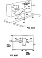
- Figure 6(a) illustrates a light section embodiment of the invention which utilizes a diode laser 306 in a housing 300 to project, via a cylinder lens 308, a strip zone of light across the gap 312 via a prism 310.
- This light when imaged by a lens 315, also via the prism 310, provides two images, one of each side of the gaps 320 and 321 onto diode array 322. This gives the contour of the radius of the edge which also allows one to calculate back from the gap to find the choice of points for flushness measurement.
- the gap so measured is in general not the mechanical gap since the amount of light coming back may not be suffucient from the tangential edges.
- the actual mechanical gap is narrower than the apparent (optical) gap.
- the sensor housing 300 could be laid on to the surface of one panel and used to sense the other or it can be robot mounted as in Figure 5, or hand-held as Figures 3(a) - 3(c) and useable both on gage rails and completed car bodies.
- the operation of the embodiment of Figure 6(a) is considered in more detail below in connection with Figure 6(b).
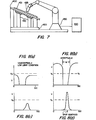
- Figure 7 illustrates the use of a typical gage ring 400 mounted on a base 420 containing supports 410 onto which a panel 401 is supported relative to the gage rail on the locating points.
- a sensor unit 425 which can, for example, be either of the types dicussed in connection with Figures 5 or 6 above, is located on a robot 430 which is moved under control of a computer 450. This robot then moves the sensor unit to each of the positions along the gage rail in question taking the data either pointwise as shown in Figure l(b), points "a", "b”, etc., or in a scanning mode as shown in Figure 4 where the robot 430 simply moves the sensor unit 425 along the rail parallel to the gap.
- the gage rail need not be an expensive precision tooled component at all but can simply be formed into place possibly even using destructible material such as wood or plastic.
- a master panel premeasured on a coordinate measuring machine, for example
- the robot to then scan that panel relative to the ring and from that determine the ring coordinates from which future panels would be compared.
- Comparison of more than one master panel in this way e.g., "max" and "min” size masters, would allow one to better set it up.
- a narrow bandpass filter such as filter 59 of Figure l(a) can optionally be used to desirably reject ambient light.
- First LEDs 50-52 (and/or other edge illumination sources as appropriate) are turned on by microcomputer readout 61 and rail edges 34 and panel edge 41 are illuminated (together with nearby portions of said rail and panel).
- the image of the panel and rail so illuminated is formed by lens 48 on detector array 50, a Reticon 512 G comprising 512 elements on .001" centers.
- Lens magnification is typically in the range of 0.5:1 to 2:1, with approximately 1:1 being most desirable with this choice of detector array (approx. 2:1 is shown in the drawing).
- the detector array is scanned out under control of microcomputer 61 and the values of the individual detector element intensities are read into memory.
- the array output is analyzed and if the edge image transition is over a certain value, the reading of gap image "W" is accepted. This is illustrated in Figures 8(a) and 8(b). If light level is insufficient, array integration time and/or light power is increased by an increment and a second scan made. This procedure is continued until sufficient edge intensity is obtained.
- the gap image W is calculated as the number of detector elements less than threshold value v. If magnification is 1:1, this is equal to gap W.
- the height H is determined as follows.
- the diode laser spot 47 projected on the surface is imaged by lens 48 to a spot image 49 on array 50.
- the position of the spot 49 on said array is a function of the height of panel 40 relative to the lens 48, itself supported by a housing positioned rigidly on gage rail 30, as a reference. Because of the included angle 0 between the lens axis and the incidence direction of the projected spot, a change in position of the panel, for example, away from the sensor would cause the spot 49 to fall to the right.
- This spot position can be related to panel position H using known triangulation equations, or by suitably calibrating the system (by placing a panel at known H values) and using a table of calibration values stored in computer 61.
- the light level for flushness measurement can also be controlled by reading the array elements and determining if the value exceeds the threshold, as shown in Figures 8(c) and 8(d).
- a reference detector such as unit 60 shown in Figure 3(a), can be used to detect reflected light spot intensity to control light power or integration time.
- the number of detectors above a certain intensity level V gives the width W. It is noted that by incrementing power or integration levels, and averaging scans above the level, a statistical resolution in excess of the diode spacing is obtained.
- the image section of strip 312 on panel 313 is scanned raster fashion and the edge 340 is determined as the last observable image point, in column 105 of a 256 x 244 element ma - trix diode array (such as a GE TN2500) shown in Figure 6(b).
- 0 typically 40 - 90 degrees
- the quantity "H” is found by determining the surface locations of the quasi-linear sections 350 and 351 of the two respective edge images (typically occuring 0.25" away from the edge or more) and by determining the matrix element row in which they fall, thereby obtaining a value for H. Centroid finding circuitry disclosed in the above-referenced applications can be used for this. Straight line fit equations can be calculated by the microcomputer if desirable and any tilt of both panels relative to the sensor can thus be removed.
- the apparent gap "W so measured is often larger than the actual mechanical gap “W” m , because light is undetectable from the actual tangential edge area. This is particularly true if low powered light sources are used on black painted cars, for example. In this case, it is desirable to fit curves to the edge radius zones 370 and 371 of the image sections and estimate from these curves where the tangent points should be, so as to predict the mechanical gap W.
- microcomputer 61 typically an Intel 8085 with 64K memory, can be used to calculate over, for example, 100 panels of the same type, the statistical distribution X and R (mean and range) at each of the, say, 20 panel points measured, for both flushness and gap. This data is then used to control the welding or stamping process for example.
- wavelengths of electromagnetic radiation in the visible and near infra-red portions of the spectrum are preferred for these measurements. It is further noted that the invention may be used to measure only gap or only flushness. In these cases, components not required can be eliminated from the embodiments shown.
- Such sensors have proven very reliable and capable of 0.1mm or better repeatability under many car panel conditions.
- the flushness measurement often exceeds 0.05 mm.
- the light source 64 or reflective tape 55 used to provide, in effect, transmitted light illumination of panel edges can be attached to the sensor housing (such as housing 29 of Figure l(a)) itself and inserted through the gap in a manner so not to interfere with the field of view of the imaging system.
Landscapes
- Physics & Mathematics (AREA)
- General Physics & Mathematics (AREA)
- Length Measuring Devices By Optical Means (AREA)
Applications Claiming Priority (2)
| Application Number | Priority Date | Filing Date | Title |
|---|---|---|---|
| US06/512,739 US4666303A (en) | 1983-07-11 | 1983-07-11 | Electro-optical gap and flushness sensors |
| US512739 | 1983-07-11 |
Publications (1)
| Publication Number | Publication Date |
|---|---|
| EP0132200A1 true EP0132200A1 (de) | 1985-01-23 |
Family
ID=24040354
Family Applications (1)
| Application Number | Title | Priority Date | Filing Date |
|---|---|---|---|
| EP84401474A Withdrawn EP0132200A1 (de) | 1983-07-11 | 1984-07-11 | Elektrooptischer Fugen- und Bündigkeitsdetektor |
Country Status (2)
| Country | Link |
|---|---|
| US (1) | US4666303A (de) |
| EP (1) | EP0132200A1 (de) |
Cited By (13)
| Publication number | Priority date | Publication date | Assignee | Title |
|---|---|---|---|---|
| US4878754A (en) * | 1986-10-16 | 1989-11-07 | Tokyo Keiki Co. Ltd. | Method of and apparatus for measuring irregularities of road surface |
| AU598967B2 (en) * | 1988-02-22 | 1990-07-05 | Kabushiki Kaisha Toshiba | Method and apparatus for measuring wedge |
| US5046851A (en) * | 1987-03-18 | 1991-09-10 | Davy Mckee (Poole) Limited | Position sensing method and apparatus |
| GB2271633A (en) * | 1992-10-19 | 1994-04-20 | Tabarelli Werner | Position detection devices |
| DE19532767A1 (de) * | 1995-09-05 | 1997-03-06 | Fraunhofer Ges Forschung | Triangulationsverfahren |
| EP0845656A1 (de) * | 1996-12-02 | 1998-06-03 | Espace Industrie Contrôle S.A. | System zum Messen des Spiels und der Koplanarität zweier nebeneinander liegender Objekte |
| EP1355126A1 (de) * | 2002-04-18 | 2003-10-22 | Perceptron GmbH | Verfahren zum Vermessen des Fügebereiches zwischen Bauteilen |
| WO2009016367A1 (en) * | 2007-07-31 | 2009-02-05 | Third Dimension Software Limited | Optical triangulation sensor |
| FR2926364A1 (fr) * | 2008-01-16 | 2009-07-17 | Peugeot Citroen Automobiles Sa | Dispositif et procede de mesure automatique de jeux et/ou d'affleurements |
| CN102435138A (zh) * | 2010-08-31 | 2012-05-02 | 西门子公司 | 确定机动车辆的车身件的间隙和/或齐平性的方法及测量装置 |
| EP2937664A1 (de) * | 2014-04-21 | 2015-10-28 | Lockheed Martin Corporation | System und verfahren zur prüfung der oberflächenbündigkeit |
| CN110298853A (zh) * | 2019-07-04 | 2019-10-01 | 易思维(杭州)科技有限公司 | 面差视觉检测方法 |
| DE102019123551A1 (de) * | 2019-09-03 | 2021-03-04 | Dr. Ing. H.C. F. Porsche Aktiengesellschaft | Verfahren zur Prüfung und/oder Vermessung eines Spalts zwischen einem ersten Werkstück und einer Referenzkontur einer Prüflehre, Fertigungsverfahren und Prüflehre |
Families Citing this family (29)
| Publication number | Priority date | Publication date | Assignee | Title |
|---|---|---|---|---|
| KR900006577B1 (ko) * | 1986-10-03 | 1990-09-13 | 엔티티 기쥬쯔이덴 가부시끼가이샤 | 형상 측정기 |
| US5104216A (en) * | 1988-12-05 | 1992-04-14 | Igm Industriegerate- Und Maschinenfabriksgesellschaft Mbh | Process for determining the position and the geometry of workpiece surfaces |
| US5245409A (en) * | 1991-11-27 | 1993-09-14 | Arvin Industries, Inc. | Tube seam weld inspection device |
| US5416590A (en) * | 1993-04-19 | 1995-05-16 | Tma Technologies, Inc. | Apparatus and process for measuring gap and mismatch |
| US5457395A (en) * | 1994-07-18 | 1995-10-10 | Ford Motor Company | System and apparatus for measuring gaps between non-parallel surfaces |
| US5600435A (en) * | 1995-05-24 | 1997-02-04 | Fori Automation, Inc. | Intelligent sensor method and apparatus for an optical wheel alignment machine |
| DE19748239A1 (de) * | 1996-10-31 | 1998-05-20 | Fori Automation Inc | Verfahren und Vorrichtung zur berührungslosen Bestimmung von Sturz und Vorlauf eines Fahrzeugrads |
| DE19910699B4 (de) * | 1999-03-10 | 2006-04-27 | Inos Automationssoftware Gmbh | Anordnung zum Messen der Breite eines Spalts, Spaltmessanordnung und Messverfahren |
| DE10012138B4 (de) * | 2000-03-13 | 2010-02-25 | Sick Ag | Verfahren und Vorrichtung zur Erfassung von Kantenbereichen von Objekten |
| US6839144B2 (en) * | 2001-03-25 | 2005-01-04 | Omron Corporation | Optical displacement sensor |
| DE10228515A1 (de) * | 2002-06-26 | 2004-01-22 | Zett-Mess-Technik Gmbh | Höhenmess- und Anreißgerät |
| US6970254B2 (en) * | 2002-09-11 | 2005-11-29 | Northrop Grumman Corporation | Robotic vision system to locate Z-forms |
| DE10242710A1 (de) * | 2002-09-13 | 2004-04-08 | Daimlerchrysler Ag | Verfahren zum Herstellen eines Verbindungsbereiches auf einem Werkstück |
| US6991755B2 (en) * | 2003-04-17 | 2006-01-31 | Northrop Grumman Corporation | Syntactic tunnel core |
| DE10348500B4 (de) * | 2003-10-18 | 2009-07-30 | Inos Automationssoftware Gmbh | Verfahren und Vorrichtung zum Erfassen eines Spaltmaßes und/oder eines Versatzes zwischen einer Klappe eines Fahrzeugs und der übrigen Fahrzeugkarosserie |
| FR2922639B1 (fr) * | 2007-10-23 | 2009-12-11 | Peugeot Citroen Automobiles Sa | Procede et dispositif de mesure de jeu et d'affleurement entre des pieces fixees sur un ensemble en l'absence de l'une d'elles |
| JP4883429B2 (ja) * | 2010-03-26 | 2012-02-22 | 住友金属工業株式会社 | Uoe鋼管の製造方法および製造装置 |
| KR20130072213A (ko) * | 2010-05-19 | 2013-07-01 | 가부시키가이샤 니콘 | 형상 측정 장치 및 형상 측정 방법 |
| JP5614633B2 (ja) * | 2010-07-29 | 2014-10-29 | 国立大学法人九州工業大学 | 回転工具と被加工物間の間隙長さ測定方法及びシステム |
| US8514412B2 (en) * | 2011-05-28 | 2013-08-20 | The Boeing Company | Portable gauge and method for measuring tape gaps |
| DE102011116791B4 (de) * | 2011-10-24 | 2014-05-15 | SmartRay GmbH | Optisches Prüfverfahren mit Mehrfach-Auslesung/Einfrieren |
| CN102914264A (zh) * | 2012-11-16 | 2013-02-06 | 上海理工大学 | 汽车前照灯总成安装面差的快速测量系统 |
| US9031311B2 (en) * | 2013-02-28 | 2015-05-12 | The Boeing Company | Identification of aircraft surface positions using camera images |
| JP2014228393A (ja) * | 2013-05-22 | 2014-12-08 | 株式会社ハーモニック・ドライブ・システムズ | 隙間測定装置 |
| KR102474345B1 (ko) * | 2016-12-14 | 2022-12-05 | 현대자동차 주식회사 | 차량용 갭 단차 측정기를 구비한 갭 단차 측정 시스템 |
| JP6999298B2 (ja) * | 2017-06-26 | 2022-01-18 | 株式会社ミツトヨ | 画像測定装置 |
| US12608789B2 (en) * | 2021-02-15 | 2026-04-21 | Amgen Inc. | Systems and methods for automated in-line plunger depth measurement |
| DE102023003723A1 (de) | 2022-09-23 | 2024-03-28 | Mercedes-Benz Group AG | System zur Ausrichtung einer Verschlussanordnung und zur Verminderung von Schwingungsgeräuschen in einem Fahrzeug und Verfahren hierzu |
| EP4602233A1 (de) * | 2022-10-14 | 2025-08-20 | Cornellcookson, Llc | Türbetätigungssensor und logik für vertikal gestapelte plattentürsysteme |
Citations (2)
| Publication number | Priority date | Publication date | Assignee | Title |
|---|---|---|---|---|
| DE2906641A1 (de) * | 1979-02-21 | 1980-08-28 | Freudenberg Carl Fa | Verfahren zur optisch-elektrischen messung des abstandes zwischen einer messeinrichtung und einem pruefling |
| DE3104320A1 (de) * | 1980-02-11 | 1981-12-17 | General Electric Co., Schenectady, N.Y. | "vorrichtung und verfahren zur optischen abstandsbestimmung" |
Family Cites Families (10)
| Publication number | Priority date | Publication date | Assignee | Title |
|---|---|---|---|---|
| GB783524A (en) * | 1954-05-21 | 1957-09-25 | Siemens Ag | Means for measuring and/or recording the air gap between the parts of a machine |
| US3180205A (en) * | 1960-06-09 | 1965-04-27 | Itt | Distance measuring apparatus having a digital output circuit |
| GB1449044A (en) * | 1972-11-14 | 1976-09-08 | Kongsberg Vapenfab As | Procedures and apparatuses for determining the shapes of surfaces |
| JPS55142254A (en) * | 1979-04-25 | 1980-11-06 | Hitachi Ltd | Inspecting method for pattern of printed wiring board |
| US4373804A (en) * | 1979-04-30 | 1983-02-15 | Diffracto Ltd. | Method and apparatus for electro-optically determining the dimension, location and attitude of objects |
| JPS55146005A (en) * | 1979-05-01 | 1980-11-14 | Sumitomo Special Metals Co Ltd | Automatic measuring method of fine size |
| JPS6039964B2 (ja) * | 1980-02-22 | 1985-09-09 | 日本鋼管株式会社 | 溶接開先中心位置検出装置 |
| JPS5882106A (ja) * | 1981-11-10 | 1983-05-17 | Shin Meiwa Ind Co Ltd | すきまセンサ |
| US4498776A (en) * | 1982-08-23 | 1985-02-12 | General Motors Corporation | Electro-optical method and apparatus for measuring the fit of adjacent surfaces |
| US4541721A (en) * | 1983-03-17 | 1985-09-17 | Perceptron, Inc. | Optical checking apparatus and method of using same |
-
1983
- 1983-07-11 US US06/512,739 patent/US4666303A/en not_active Expired - Lifetime
-
1984
- 1984-07-11 EP EP84401474A patent/EP0132200A1/de not_active Withdrawn
Patent Citations (2)
| Publication number | Priority date | Publication date | Assignee | Title |
|---|---|---|---|---|
| DE2906641A1 (de) * | 1979-02-21 | 1980-08-28 | Freudenberg Carl Fa | Verfahren zur optisch-elektrischen messung des abstandes zwischen einer messeinrichtung und einem pruefling |
| DE3104320A1 (de) * | 1980-02-11 | 1981-12-17 | General Electric Co., Schenectady, N.Y. | "vorrichtung und verfahren zur optischen abstandsbestimmung" |
Cited By (19)
| Publication number | Priority date | Publication date | Assignee | Title |
|---|---|---|---|---|
| US4878754A (en) * | 1986-10-16 | 1989-11-07 | Tokyo Keiki Co. Ltd. | Method of and apparatus for measuring irregularities of road surface |
| US5046851A (en) * | 1987-03-18 | 1991-09-10 | Davy Mckee (Poole) Limited | Position sensing method and apparatus |
| AU598967B2 (en) * | 1988-02-22 | 1990-07-05 | Kabushiki Kaisha Toshiba | Method and apparatus for measuring wedge |
| GB2271633A (en) * | 1992-10-19 | 1994-04-20 | Tabarelli Werner | Position detection devices |
| DE19532767C2 (de) * | 1995-09-05 | 2000-12-28 | Fraunhofer Ges Forschung | Triangulationsverfahren |
| DE19532767A1 (de) * | 1995-09-05 | 1997-03-06 | Fraunhofer Ges Forschung | Triangulationsverfahren |
| EP0845656A1 (de) * | 1996-12-02 | 1998-06-03 | Espace Industrie Contrôle S.A. | System zum Messen des Spiels und der Koplanarität zweier nebeneinander liegender Objekte |
| FR2756626A1 (fr) * | 1996-12-02 | 1998-06-05 | Espace Ind Controle Sa | Systeme de mesure de jeux et d'affleurements entre des pieces en vis-a-vis |
| US5999265A (en) * | 1996-12-02 | 1999-12-07 | Espace Industrie Controles S.A. | System for measuring gap and mismatch between opposing parts |
| EP1355126A1 (de) * | 2002-04-18 | 2003-10-22 | Perceptron GmbH | Verfahren zum Vermessen des Fügebereiches zwischen Bauteilen |
| WO2009016367A1 (en) * | 2007-07-31 | 2009-02-05 | Third Dimension Software Limited | Optical triangulation sensor |
| FR2926364A1 (fr) * | 2008-01-16 | 2009-07-17 | Peugeot Citroen Automobiles Sa | Dispositif et procede de mesure automatique de jeux et/ou d'affleurements |
| CN102435138A (zh) * | 2010-08-31 | 2012-05-02 | 西门子公司 | 确定机动车辆的车身件的间隙和/或齐平性的方法及测量装置 |
| CN102435138B (zh) * | 2010-08-31 | 2016-01-20 | 西门子公司 | 确定机动车辆的车身件的间隙和/或齐平性的方法以及测量装置 |
| EP2937664A1 (de) * | 2014-04-21 | 2015-10-28 | Lockheed Martin Corporation | System und verfahren zur prüfung der oberflächenbündigkeit |
| US10378892B2 (en) | 2014-04-21 | 2019-08-13 | Lockheed Martin Corporation | System and method for inspecting surface flushness |
| CN110298853A (zh) * | 2019-07-04 | 2019-10-01 | 易思维(杭州)科技有限公司 | 面差视觉检测方法 |
| DE102019123551A1 (de) * | 2019-09-03 | 2021-03-04 | Dr. Ing. H.C. F. Porsche Aktiengesellschaft | Verfahren zur Prüfung und/oder Vermessung eines Spalts zwischen einem ersten Werkstück und einer Referenzkontur einer Prüflehre, Fertigungsverfahren und Prüflehre |
| DE102019123551B4 (de) | 2019-09-03 | 2023-07-06 | Dr. Ing. H.C. F. Porsche Aktiengesellschaft | Verfahren zur Prüfung und/oder Vermessung eines Spalts zwischen einem ersten Werkstück und einer Referenzkontur einer Prüflehre, Fertigungsverfahren und Prüflehre |
Also Published As
| Publication number | Publication date |
|---|---|
| US4666303A (en) | 1987-05-19 |
Similar Documents
| Publication | Publication Date | Title |
|---|---|---|
| US4666303A (en) | Electro-optical gap and flushness sensors | |
| US8004694B2 (en) | System for indirectly measuring a geometric dimension related to an opening in an apertured exterior surface of a part based on direct measurements of the part when fixtured at a measurement station | |
| US11199395B2 (en) | Profile inspection system for threaded and axial components | |
| US8237935B2 (en) | Method and system for automatically inspecting parts and for automatically generating calibration data for use in inspecting parts | |
| US7812970B2 (en) | Method and system for inspecting parts utilizing triangulation | |
| US7920278B2 (en) | Non-contact method and system for inspecting parts | |
| US7796278B2 (en) | Method for precisely measuring position of a part to be inspected at a part inspection station | |
| EP3418681B1 (de) | Kalibrierung eines triangulationssensors | |
| US4647208A (en) | Method for spatial measurement of holes | |
| FI96902C (fi) | Optoelektroninen kulma-anturilaite, tätä koskeva menetelmä sekä optoelektroninen mittausjärjestelmä | |
| US7907267B2 (en) | Optical method and system for generating calibration data for use in calibrating a part inspection system | |
| AU616731B2 (en) | Method and apparatus for monitoring the surface profile of a moving workpiece | |
| US4634273A (en) | O-ring inspection method | |
| US8550444B2 (en) | Method and system for centering and aligning manufactured parts of various sizes at an optical measurement station | |
| US20090103113A1 (en) | Method and system for optically inspecting parts | |
| US4989981A (en) | Automatic quality control measuring system for automotive assembly line or the like | |
| US20090100901A1 (en) | Calibration device for use in an optical part measuring system | |
| US20210025830A1 (en) | Stone-block analysis device and methods for the evaluation of stone blocks | |
| US4498776A (en) | Electro-optical method and apparatus for measuring the fit of adjacent surfaces | |
| US4201476A (en) | Laser dimension gauge | |
| US5090811A (en) | Optical radius gauge | |
| WO2008076850A2 (en) | Apparatus and methods for measuring workpieces | |
| CN115655125A (zh) | 用于盖板玻璃油墨厚度在线检测方法及设备 | |
| US6529283B1 (en) | Method for measuring the width of a gap | |
| US6906808B2 (en) | Methods and apparatus for measuring a surface contour of an object |
Legal Events
| Date | Code | Title | Description |
|---|---|---|---|
| PUAI | Public reference made under article 153(3) epc to a published international application that has entered the european phase |
Free format text: ORIGINAL CODE: 0009012 |
|
| AK | Designated contracting states |
Designated state(s): DE FR GB IT SE |
|
| 17P | Request for examination filed |
Effective date: 19850704 |
|
| 17Q | First examination report despatched |
Effective date: 19861110 |
|
| STAA | Information on the status of an ep patent application or granted ep patent |
Free format text: STATUS: THE APPLICATION IS DEEMED TO BE WITHDRAWN |
|
| 18D | Application deemed to be withdrawn |
Effective date: 19870321 |
|
| RIN1 | Information on inventor provided before grant (corrected) |
Inventor name: PRYOR, TIMOTHY R. |