EP0132254A2 - Cage d'armature pour le renforcement spatial de structures en béton armé - Google Patents
Cage d'armature pour le renforcement spatial de structures en béton armé Download PDFInfo
- Publication number
- EP0132254A2 EP0132254A2 EP84890133A EP84890133A EP0132254A2 EP 0132254 A2 EP0132254 A2 EP 0132254A2 EP 84890133 A EP84890133 A EP 84890133A EP 84890133 A EP84890133 A EP 84890133A EP 0132254 A2 EP0132254 A2 EP 0132254A2
- Authority
- EP
- European Patent Office
- Prior art keywords
- brackets
- reinforcement
- connecting rods
- reinforcement cage
- outline
- Prior art date
- Legal status (The legal status is an assumption and is not a legal conclusion. Google has not performed a legal analysis and makes no representation as to the accuracy of the status listed.)
- Granted
Links
Images


Classifications
-
- E—FIXED CONSTRUCTIONS
- E04—BUILDING
- E04C—STRUCTURAL ELEMENTS; BUILDING MATERIALS
- E04C5/00—Reinforcing elements, e.g. for concrete; Auxiliary elements therefor
- E04C5/01—Reinforcing elements of metal, e.g. with non-structural coatings
- E04C5/06—Reinforcing elements of metal, e.g. with non-structural coatings of high bending resistance, i.e. of essentially three-dimensional [3D] extent, e.g. lattice girders
- E04C5/0604—Prismatic or cylindrical reinforcement cages composed of longitudinal bars and open or closed stirrup rods
- E04C5/0609—Closed cages composed of two or more coacting cage parts, e.g. transversally hinged or nested parts
-
- E—FIXED CONSTRUCTIONS
- E04—BUILDING
- E04C—STRUCTURAL ELEMENTS; BUILDING MATERIALS
- E04C5/00—Reinforcing elements, e.g. for concrete; Auxiliary elements therefor
- E04C5/01—Reinforcing elements of metal, e.g. with non-structural coatings
- E04C5/06—Reinforcing elements of metal, e.g. with non-structural coatings of high bending resistance, i.e. of essentially three-dimensional [3D] extent, e.g. lattice girders
- E04C5/0604—Prismatic or cylindrical reinforcement cages composed of longitudinal bars and open or closed stirrup rods
- E04C5/0618—Closed cages with spiral- or coil-shaped stirrup rod
Definitions
- the invention relates to a reinforcement cage for spatial reinforcements of reinforced concrete bodies, in particular for cage-like reinforcements for rod-shaped concrete components, such as columns, beams, bored piles or the like, which reinforcement cage is formed from brackets running in the circumferential direction over the full circumference and to be joined together with a longitudinal reinforcement formed by bars, with which they form the reinforcement, is provided, the brackets forming the reinforcement cage being connected to one another by two longitudinal connecting rods arranged on the outside of the brackets and being held in the mutual spacing of the brackets provided in the spatial reinforcement, and in particular the connecting rods are made of steel and are welded to the brackets.
- Spatial reinforcements which consist of a longitudinal reinforcement formed by bars and a transverse reinforcement formed by brackets running transversely to the bars of this longitudinal reinforcement, are used extensively in construction. These are in particular spatial reinforcements for rod-shaped concrete components, such as columns, beams, bored piles or the like. Such reinforcements are usually produced on the construction site, the bars forming the longitudinal reinforcement and the brackets forming the transverse reinforcement first being brought into the intended relative position to one another and then connected to one another, which connection is usually carried out using binding wire, after which these reinforcements to be built in.
- Reinforcement cages are also known, which are provided for forming spatial reinforcements of beams or posts made of reinforced concrete and consist of brackets running along the circumference and longitudinally running connecting rods arranged on the outside of these brackets.
- two or more such reinforcement cages are intended to be pushed one into the other following one or more direction (s) until the brackets are aligned with one another in order to obtain a reinforcement with greater resilience, and so on
- all longitudinal bars of such a reinforcement cage are arranged on the section of the bracket circumference lying on one side of a reference straight line running through the geometric center of the transverse frame;
- a tapering shape of the bracket or an arrangement of the longitudinal connecting rods on spacers is provided for inserting the brackets of a reinforcing cage between the longitudinal connecting rods of another reinforcing cage.
- the reinforcement cage according to the invention of the type mentioned at the outset is characterized in that the longitudinal connecting rods - to enable easy stacking of at least three such reinforcement cages in a transverse direction - only at the two interfaces of the frame outline with a straight line passing through the center of gravity of the frame outline, or in the The immediate vicinity of these interfaces lies on the outside of the brackets, whereby in the case of a polygonal bracket outline, this straight line leads at least through a corner area of the bracket outline or through the immediate vicinity of this corner area, and if the longitudinal connecting rods are placed in the vicinity of the interfaces mentioned, these connecting rods are preferably arranged on both sides of the straight line.
- a reinforcement cage of the type mentioned at the beginning allows the above-mentioned objective to be met very well, and such reinforcement cages can be attached to one of the The production site remote from the construction site, where facilities for an economical and exact positioning and connection of the brackets can be installed, manufacture in advance and a larger number of such reinforcement cages are nested in a transport unit in a transverse direction. Transport the construction site so that the transport volume required for this transport is relatively low due to the package-like combination of a number of reinforcement cages.
- the interfaces of the straight line through the center of gravity of the temple outline with the temple outline correspond to the points of contact of the temple outline with two parallel straight lines, which are applied to the temple outline from the outside and do not intersect the temple outline.
- brackets are rectangular in shape and the longitudinal connecting rods are arranged on opposite sides of the rectangle at the beginning of the curvatures forming the corners of the brackets.
- Brackets are circular in shape and the longitudinal connecting rods only at the intersections of the bracket outlines with a diameter line or in the immediate vicinity of these intersections.
- the brackets are formed by at least one helically bent rod, which successively embodies several brackets, with bending points and straight sections possibly also being provided in the course of the helical course.
- This development is particularly advantageous in terms of the manufacturing process and the cost of materials;
- the separating work required to produce individual brackets is eliminated, and the material expenditure required for individual brackets to connect the two ends of the same is eliminated, and moreover, the work steps required for joining the bracket parts to the longitudinal connecting rods become processable individual bracket simplified, since the continuous spiral largely eliminates the need to align the bracket when processing individual brackets before assembling with the longitudinal connecting rods; due to the bending points and straight sections of the helix, which may be provided in the course of the helical course, the helix can also be made in the manner of polygonally curved brackets, e.g. rectangular curved bow, be formed.
- the longitudinal connecting rods also come with other materials, e.g. Plastic, and techniques other than welding for connection to the brackets, such as a connection using clamp connectors or sleeves, such a connection has the advantage that it can be easily removed at any time if necessary, or a connection by gluing or soldering.
- the reinforcement cages designed according to the invention can be produced in lengths which correspond to the length of the reinforcement to be produced in the respective application; but you can also use reinforcement cages using several reinforcement cages, which are in succession with the longitudinal reinforcement of the relevant reinforcement. Bars are to be joined together, if this, e.g. for transport or organizational reasons, is considered advantageous; so you can e.g. Manufacture reinforcement cages in standard lengths and successively combine several such reinforcement cages corresponding to the length of the reinforcements to be formed in the case in question with the bars forming the longitudinal reinforcement, with such a reinforcement cage of each reinforcement to a certain measure to maintain the specified overall length to form a certain predetermined total length the reinforcement cages joined together must be shortened.
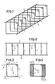
- FIGS. 1 to 3 The embodiment of a reinforcement cage shown in FIGS. 1 to 3 is formed from a number of brackets 1, which are connected to two longitudinal connecting rods 2.
- the bracket 1 run in the circumferential t clothes over their fully closed and have a rectangular outline.
- the longitudinal connecting rods 2 are fixed to the brackets 1 and hold them in the mutual positions and spacings provided when using such a reinforcement cage to form a spatial reinforcement.
- a spatial reinforcement formed by bars 4 is arranged within the bracket 1, the position of the bars 4 forming the longitudinal reinforcement provided in the reinforcement being secured by connecting the bars 4 to the brackets 1. This connection can be made with binding wire, for example.
- the longitudinal connecting rods 2 are connected to the brackets at those points on the outline of the bracket which at the same time also the points of contact of two straight lines 6 which are parallel to one another and which are applied from the outside to the outline of the bracket 1 and do not intersect the outline of the bracket, form with the temple outline. These points of contact also correspond to the interfaces of a straight line 8 through the center of gravity 7 of the wing outline with the wing outline. If the longitudinal bars 2 are placed directly at the corner of the bracket 1, as is provided in the variant according to FIG. 6, there is a particularly simple manipulation when pushing together a number of such reinforcement cages to form a stack, when pushing them together in the direction of the diagonal 11 the bracket should take place.
- the stirrups are realized by two rectangles forming a cross shape with one another. Even with such shaped temples it is suitable Arrangement of the longitudinal connecting rods on the brackets possible to achieve a stacked stack of several reinforcement cages formed with such brackets.
- the longitudinal connecting rods 2 are placed in the region of the contact points between two straight lines 6 which are parallel to one another and which are applied to the brackets 1 from the outside with the outlines of these brackets; the course of the parallel straight lines 6 is to be chosen so that they do not intersect the frame outline at any point.
- the resulting points of contact also correspond to the intersections of the straight lines passing through the center of gravity 7 with the outline of the bracket.
- the embodiment of a reinforcement cage shown in front view in FIG. 8 is formed from circularly shaped brackets 1 and longitudinal connecting rods 2, which are attached to the outside of the brackets 1 at the geometrical interfaces of the bracket with a straight line 15 in diameter. These interfaces also coincide with the contact points of two parallel straight lines 6, which are applied to the outside of the bracket and do not intersect the bracket outline.
- This placement of the longitudinal connecting rods 2 on the brackets 1 of this reinforcement cage enables several such reinforcement cages to be pushed together in the transverse direction symbolized by the arrow 5 to form a densely packed stack, as is shown in FIG. 9.
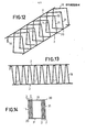
- the stirrups 1 are formed by successive zones of a helically bent rod 18, which successively embodies several stirrups 1.
- the individual zones of the rod 18, which embody the brackets 1, are held relative to one another by the longitudinal connecting rods 2, which are connected to the zones of the rod 18 forming the brackets 1.
- brackets of the reinforcement cage by a helically curved rod can also be varied in such a way that 18 bending points 20 are provided in the course of the helical course of such a rod, wherein the sections 21 running between such bending points 20 can either be curved or straight, such as this is the case in the embodiment according to FIGS. 12 and 13.
- This embodiment corresponds in terms of the shape of the brackets 1 formed by successive sections of the coiled rod 18 to a reinforcement cage with polygonally shaped brackets.
- brackets 1 In the embodiment of a reinforcement cage shown in front view in FIG. 15, odd-numbered polygonal, namely triangular, brackets 1 are provided, and there is a longitudinal connecting rod 2a in FIG Area of a bracket corner 22 and a second longitudinal connecting rod 2b arranged on the triangle side 23 opposite this bracket corner 22.
- the longitudinal connecting rods 2a, 2b are placed in the area of the contact points of the frame outline with parallel straight lines 6, which are placed on the outside of the frame outline and do not intersect the frame outline, and these points of contact correspond to the Interfaces of a straight line 8 passing through the center of gravity 7 with the bow outline.
- FIG. 16 The formation of reinforcements using a plurality of reinforcement cages lined up in a row is shown schematically in FIG. 16.
- the reinforcement cages which in turn, as discussed in connection with the preceding embodiments, are formed from brackets 1 and longitudinal connecting rods 2, can have standardized lengths 27, 28, these lengths both from the point of view of being as universal as possible and from the point of view of in the manufacturing given options and from the point of view of transport options can be chosen.
- the prefabricated reinforcement cages can also be provided in various standard lengths 27, 28 and, if necessary, reinforcement cages 25, 26, which have different length dimensions, can be used together to produce the spatial reinforcement to be formed, as shown in FIG. 16 is.
- reinforcement cages with standard lengths can be produced without difficulty by appropriately separating the longitudinal connecting rods, which then together with other reinforcement cages result in the required length.
- a corresponding determination can be made in the manufacture of the reinforcement cages; there is also the possibility of influencing the size of the distances between the brackets 1 present in the reinforcement by appropriately selecting the distances 29 between the reinforcement cages 25, 26 lined up to form the spatial reinforcement.
Landscapes
- Engineering & Computer Science (AREA)
- Architecture (AREA)
- Civil Engineering (AREA)
- Structural Engineering (AREA)
- Reinforcement Elements For Buildings (AREA)
- Working Measures On Existing Buildindgs (AREA)
- Bridges Or Land Bridges (AREA)
Applications Claiming Priority (2)
| Application Number | Priority Date | Filing Date | Title |
|---|---|---|---|
| AT2609/83 | 1983-07-15 | ||
| AT0260983A AT379636B (de) | 1983-07-15 | 1983-07-15 | Bewehrungskorb fuer raeumliche armierungen von stahlbetonkoerpern |
Publications (3)
| Publication Number | Publication Date |
|---|---|
| EP0132254A2 true EP0132254A2 (fr) | 1985-01-23 |
| EP0132254A3 EP0132254A3 (en) | 1986-04-09 |
| EP0132254B1 EP0132254B1 (fr) | 1989-09-20 |
Family
ID=3537328
Family Applications (1)
| Application Number | Title | Priority Date | Filing Date |
|---|---|---|---|
| EP84890133A Expired EP0132254B1 (fr) | 1983-07-15 | 1984-07-13 | Cage d'armature pour le renforcement spatial de structures en béton armé |
Country Status (3)
| Country | Link |
|---|---|
| EP (1) | EP0132254B1 (fr) |
| AT (2) | AT379636B (fr) |
| DE (1) | DE3479825D1 (fr) |
Cited By (11)
| Publication number | Priority date | Publication date | Assignee | Title |
|---|---|---|---|---|
| EP0152397A3 (fr) * | 1984-01-24 | 1988-03-30 | Rakennusvalmiste Oy | Armature en hélice pour éléments en béton préfabriqués et procédé pour la fabrication de cette armature |
| GB2197357A (en) * | 1986-11-07 | 1988-05-18 | Gordon Bramwell Dodson | Staging comprising framing partly nestable within a similar frame |
| WO1988006665A1 (fr) * | 1987-03-05 | 1988-09-07 | Georgi Oroschakoff | Armature pour constructions en beton arme |
| GR1000058B (el) * | 1989-04-24 | 1990-06-27 | Kollios Ioannis O E | Συγκολλημενος μανδυας υποστηλωματων δοκων και τειχιων |
| EP0394815A1 (fr) * | 1989-04-22 | 1990-10-31 | Hinrich Podendorf | Cage d'armature en acier |
| WO2001078083A1 (fr) * | 2000-04-11 | 2001-10-18 | Oyster International Nv | Dispositif de stockage d'une matiere dangereuse |
| EP1764448B1 (fr) * | 2005-09-16 | 2013-08-28 | Laing O'Rourke Plc | Dispositifs de connection à noyer dans le béton |
| CN105544772A (zh) * | 2015-12-03 | 2016-05-04 | 文登蓝岛建筑工程有限公司 | 一种墙板固定件 |
| US10563403B1 (en) | 2018-10-30 | 2020-02-18 | King Saud University | Multi-leg fiber reinforced concrete |
| US10927548B1 (en) | 2020-02-20 | 2021-02-23 | King Saud University | Fiber elements for soil stabilization |
| CN117921822A (zh) * | 2024-03-20 | 2024-04-26 | 中国十七冶集团有限公司 | 一种3d打印混凝土竖向构件配筋方法及其配筋系统 |
Families Citing this family (3)
| Publication number | Priority date | Publication date | Assignee | Title |
|---|---|---|---|---|
| SG109413A1 (en) * | 1999-10-14 | 2005-03-30 | Natsteel Asia Pte Ltd | Collapsible cage |
| CH709859B1 (de) * | 2014-07-09 | 2018-09-28 | Fischer Rista Ag | Bewehrungskorb und Erdbeben-Bügelbewehrung. |
| DE102016106290A1 (de) | 2016-04-06 | 2017-10-12 | Daniel Hagmann | Bewehrungselement |
Family Cites Families (9)
| Publication number | Priority date | Publication date | Assignee | Title |
|---|---|---|---|---|
| BE555849A (fr) * | ||||
| US1950343A (en) * | 1930-09-06 | 1934-03-06 | Kalman Steel Co | Reenforcement for headers and stretchers |
| LU48114A1 (fr) * | 1964-03-06 | 1965-05-03 | ||
| BE766864R (fr) * | 1970-05-12 | 1971-10-01 | Oroschakoff Georgi | Armatures pour constructions et beton |
| AT304834B (de) * | 1970-07-03 | 1973-01-25 | Josef Hell Dipl Ing | Bewehrungskorb für Säulen, Balken od.dgl. aus Stahlbeton |
| DE2042658A1 (de) * | 1970-08-28 | 1972-03-02 | Ellner, Karl Erik Olof Tage, Lidingö (Schweden) | Bewehrungselement |
| AT340650B (de) * | 1975-10-02 | 1977-12-27 | Bucher Franz | Bewehrung, vorzugsweise fur stahlbetontragwerke |
| FR2342383A1 (fr) * | 1976-02-25 | 1977-09-23 | Treillis Panneaux Soudes | Perfectionnements aux armatures pour constructions en beton arme |
| FR2372285A1 (fr) * | 1976-11-26 | 1978-06-23 | Armel | Support de treillis soude pour planchers en beton arme |
-
1983
- 1983-07-15 AT AT0260983A patent/AT379636B/de not_active IP Right Cessation
-
1984
- 1984-07-13 DE DE8484890133T patent/DE3479825D1/de not_active Expired
- 1984-07-13 AT AT84890133T patent/ATE46554T1/de not_active IP Right Cessation
- 1984-07-13 EP EP84890133A patent/EP0132254B1/fr not_active Expired
Cited By (13)
| Publication number | Priority date | Publication date | Assignee | Title |
|---|---|---|---|---|
| EP0152397A3 (fr) * | 1984-01-24 | 1988-03-30 | Rakennusvalmiste Oy | Armature en hélice pour éléments en béton préfabriqués et procédé pour la fabrication de cette armature |
| GB2197357A (en) * | 1986-11-07 | 1988-05-18 | Gordon Bramwell Dodson | Staging comprising framing partly nestable within a similar frame |
| GB2197357B (en) * | 1986-11-07 | 1991-01-09 | Gordon Bramwell Dodson | Improvements in relating to staging |
| WO1988006665A1 (fr) * | 1987-03-05 | 1988-09-07 | Georgi Oroschakoff | Armature pour constructions en beton arme |
| EP0394815A1 (fr) * | 1989-04-22 | 1990-10-31 | Hinrich Podendorf | Cage d'armature en acier |
| GR1000058B (el) * | 1989-04-24 | 1990-06-27 | Kollios Ioannis O E | Συγκολλημενος μανδυας υποστηλωματων δοκων και τειχιων |
| WO2001078083A1 (fr) * | 2000-04-11 | 2001-10-18 | Oyster International Nv | Dispositif de stockage d'une matiere dangereuse |
| US6771731B2 (en) | 2000-04-11 | 2004-08-03 | Oyster International N.V. | Device for storage of hazardous material |
| EP1764448B1 (fr) * | 2005-09-16 | 2013-08-28 | Laing O'Rourke Plc | Dispositifs de connection à noyer dans le béton |
| CN105544772A (zh) * | 2015-12-03 | 2016-05-04 | 文登蓝岛建筑工程有限公司 | 一种墙板固定件 |
| US10563403B1 (en) | 2018-10-30 | 2020-02-18 | King Saud University | Multi-leg fiber reinforced concrete |
| US10927548B1 (en) | 2020-02-20 | 2021-02-23 | King Saud University | Fiber elements for soil stabilization |
| CN117921822A (zh) * | 2024-03-20 | 2024-04-26 | 中国十七冶集团有限公司 | 一种3d打印混凝土竖向构件配筋方法及其配筋系统 |
Also Published As
| Publication number | Publication date |
|---|---|
| ATE46554T1 (de) | 1989-10-15 |
| ATA260983A (de) | 1985-06-15 |
| EP0132254B1 (fr) | 1989-09-20 |
| AT379636B (de) | 1986-02-10 |
| DE3479825D1 (en) | 1989-10-26 |
| EP0132254A3 (en) | 1986-04-09 |
Similar Documents
| Publication | Publication Date | Title |
|---|---|---|
| EP0132254B1 (fr) | Cage d'armature pour le renforcement spatial de structures en béton armé | |
| DE3008840A1 (de) | Rahmenkonstruktion fuer ein motorfahrzeug | |
| DE102007014366A1 (de) | Bewehrungsvorrichtung für Fertigbau-Teile | |
| DE2229093A1 (de) | Montage bzw Befestigungsglied fur eine Bewehrung oder ein Bewehrungselement im Stahlbetonbau | |
| DE102016223524A1 (de) | Dämpfungs- und Federanordnung und Verfahren zu deren Herstellung | |
| DE1559490B1 (de) | Bewehrungselement fuer Balken und Stuetzen aus Stahlbeton | |
| DE2160964A1 (de) | Federung und verfahren zu ihrer herstellung | |
| DE1609814A1 (de) | Bewehrungselement fuer Stahlbetonbauteile | |
| EP0136283B1 (fr) | Armature pour constructions en béton armé | |
| EP0196542A2 (fr) | Procédé et dispositif pour la fabrication d'une cage d'armature pour des éléments de construction en béton armé | |
| EP0143101B1 (fr) | Armature pour constructions de béton armé | |
| EP0299226A2 (fr) | Coffrage pour la réalisation d'éléments de construction en béton | |
| DE3243971C2 (fr) | ||
| DE2150650C3 (de) | Abstandhalter zur Aufnahme der Längsstäbe von Bewehrungsmatten | |
| DE2350866C3 (de) | Betonstahlmatte | |
| WO1993015287A1 (fr) | Poutre en treillis | |
| DE2805984A1 (de) | Zur herstellung eines stahlbetonbalkens vorgesehener bewehrungskorb sowie verfahren zur herstellung dieses bewehrungskorbes | |
| DE2540145C3 (de) | Abstandhalter | |
| DE2214532A1 (de) | Abstandhalter fuer bewehrungsmittel | |
| AT390103B (de) | Anschlussbewehrung fuer stahlbetonkonstruktionen | |
| DE1484116A1 (de) | Das Herstellen von mattenfoermigen Bewehrungen,insbesondere fuer Stahlbeton | |
| EP0016008B1 (fr) | Treillis soude pour beton arme | |
| EP0570717A1 (fr) | Elément d'armature pour raccordement | |
| DE1559490C (de) | Bewehrungselement für Balken und Stützen aus Stahlbeton | |
| DE19632692A1 (de) | Stahlbetonbewehrung |
Legal Events
| Date | Code | Title | Description |
|---|---|---|---|
| PUAI | Public reference made under article 153(3) epc to a published international application that has entered the european phase |
Free format text: ORIGINAL CODE: 0009012 |
|
| AK | Designated contracting states |
Designated state(s): AT CH DE FR GB IT LI NL |
|
| PUAL | Search report despatched |
Free format text: ORIGINAL CODE: 0009013 |
|
| AK | Designated contracting states |
Kind code of ref document: A3 Designated state(s): AT CH DE FR GB IT LI NL |
|
| 17P | Request for examination filed |
Effective date: 19860825 |
|
| 17Q | First examination report despatched |
Effective date: 19880211 |
|
| GRAA | (expected) grant |
Free format text: ORIGINAL CODE: 0009210 |
|
| AK | Designated contracting states |
Kind code of ref document: B1 Designated state(s): AT CH DE FR GB IT LI NL |
|
| REF | Corresponds to: |
Ref document number: 46554 Country of ref document: AT Date of ref document: 19891015 Kind code of ref document: T |
|
| ET | Fr: translation filed | ||
| GBT | Gb: translation of ep patent filed (gb section 77(6)(a)/1977) | ||
| REF | Corresponds to: |
Ref document number: 3479825 Country of ref document: DE Date of ref document: 19891026 |
|
| ITF | It: translation for a ep patent filed | ||
| PLBE | No opposition filed within time limit |
Free format text: ORIGINAL CODE: 0009261 |
|
| STAA | Information on the status of an ep patent application or granted ep patent |
Free format text: STATUS: NO OPPOSITION FILED WITHIN TIME LIMIT |
|
| PG25 | Lapsed in a contracting state [announced via postgrant information from national office to epo] |
Ref country code: AT Effective date: 19900713 |
|
| 26N | No opposition filed | ||
| ITTA | It: last paid annual fee | ||
| PGFP | Annual fee paid to national office [announced via postgrant information from national office to epo] |
Ref country code: GB Payment date: 19980629 Year of fee payment: 15 |
|
| PGFP | Annual fee paid to national office [announced via postgrant information from national office to epo] |
Ref country code: FR Payment date: 19980730 Year of fee payment: 15 Ref country code: CH Payment date: 19980730 Year of fee payment: 15 |
|
| PGFP | Annual fee paid to national office [announced via postgrant information from national office to epo] |
Ref country code: NL Payment date: 19980731 Year of fee payment: 15 |
|
| PGFP | Annual fee paid to national office [announced via postgrant information from national office to epo] |
Ref country code: DE Payment date: 19980923 Year of fee payment: 15 |
|
| PG25 | Lapsed in a contracting state [announced via postgrant information from national office to epo] |
Ref country code: GB Free format text: LAPSE BECAUSE OF NON-PAYMENT OF DUE FEES Effective date: 19990713 |
|
| PG25 | Lapsed in a contracting state [announced via postgrant information from national office to epo] |
Ref country code: LI Free format text: LAPSE BECAUSE OF NON-PAYMENT OF DUE FEES Effective date: 19990731 Ref country code: FR Free format text: THE PATENT HAS BEEN ANNULLED BY A DECISION OF A NATIONAL AUTHORITY Effective date: 19990731 Ref country code: CH Free format text: LAPSE BECAUSE OF NON-PAYMENT OF DUE FEES Effective date: 19990731 |
|
| PG25 | Lapsed in a contracting state [announced via postgrant information from national office to epo] |
Ref country code: NL Free format text: LAPSE BECAUSE OF NON-PAYMENT OF DUE FEES Effective date: 20000201 |
|
| GBPC | Gb: european patent ceased through non-payment of renewal fee |
Effective date: 19990713 |
|
| REG | Reference to a national code |
Ref country code: CH Ref legal event code: PL |
|
| NLV4 | Nl: lapsed or anulled due to non-payment of the annual fee |
Effective date: 20000201 |
|
| PG25 | Lapsed in a contracting state [announced via postgrant information from national office to epo] |
Ref country code: DE Free format text: LAPSE BECAUSE OF NON-PAYMENT OF DUE FEES Effective date: 20000503 |
|
| REG | Reference to a national code |
Ref country code: FR Ref legal event code: ST |