EP0132327A2 - Elément fltre électronique plan et connecteur incorporant un tel filtre - Google Patents
Elément fltre électronique plan et connecteur incorporant un tel filtre Download PDFInfo
- Publication number
- EP0132327A2 EP0132327A2 EP84304438A EP84304438A EP0132327A2 EP 0132327 A2 EP0132327 A2 EP 0132327A2 EP 84304438 A EP84304438 A EP 84304438A EP 84304438 A EP84304438 A EP 84304438A EP 0132327 A2 EP0132327 A2 EP 0132327A2
- Authority
- EP
- European Patent Office
- Prior art keywords
- filter
- plates
- housing
- contact
- connector
- Prior art date
- Legal status (The legal status is an assumption and is not a legal conclusion. Google has not performed a legal analysis and makes no representation as to the accuracy of the status listed.)
- Withdrawn
Links
Images


Classifications
-
- H—ELECTRICITY
- H01—ELECTRIC ELEMENTS
- H01R—ELECTRICALLY-CONDUCTIVE CONNECTIONS; STRUCTURAL ASSOCIATIONS OF A PLURALITY OF MUTUALLY-INSULATED ELECTRICAL CONNECTING ELEMENTS; COUPLING DEVICES; CURRENT COLLECTORS
- H01R13/00—Details of coupling devices of the kinds covered by groups H01R12/70 or H01R24/00 - H01R33/00
- H01R13/66—Structural association with built-in electrical component
- H01R13/719—Structural association with built-in electrical component specially adapted for high frequency, e.g. with filters
- H01R13/7195—Structural association with built-in electrical component specially adapted for high frequency, e.g. with filters with planar filters with openings for contacts
-
- H—ELECTRICITY
- H03—ELECTRONIC CIRCUITRY
- H03H—IMPEDANCE NETWORKS, e.g. RESONANT CIRCUITS; RESONATORS
- H03H1/00—Constructional details of impedance networks whose electrical mode of operation is not specified or applicable to more than one type of network
Definitions
- This invention relates to a planar electronic filter element, and to a connector embodying such a filter element.
- the present invention provides such a filter and filter connector, utilizing a capacitive multiplane planar filter element.
- a filter in the present invention, comprises a plurality of dielectric plates sandwiched together, a ground plate being positioned between two plates and electrode stripes being formed on the plates on surfaces remote from the ground plate. Opposite end surfaces can be metallized to provide for connection to the ground plane, and pins or other forms of terminals are attached to the stripe electrodes. It is possible to provide a stacked assembly, with more than one ground plane.
- planar elements have been used, with electrode patterns on the outer surfaces of the dielectric plates and a ground plate patterned electrode between the dielectric plates. Pins are inserted in holes through the dielectric plates and are connected to the electrodes on the outer surfaces. Clearances are provided in the ground electrode around the pins to prevent shorting and electrical breakdown.
- Such construction is relatively complex and expensive and obtaining good alignment between electrodes on the outer surfaces and the electrode patterns between the dielectric plates is often difficult. This can make obtaining accurate and consistent electrical characteristics difficult and expensive.
- a plurality of parallel, spaced, electrode stripes are formed across the outer surfaces.
- Terminal pins can be mounted on the electrodes, or conductors attached to the electrodes. Alternatively, contact with the electrodes can be made by contact members in cooperating parts. No forming of holes in the dielectric plates is necessary.
- the ground electrode or plate can extend in a continuous layer between the dielectric plates and the electrodes on the outer surfaces of the plates are easily and accurately positioned, generally in the form of spaced parallel stripes. Alignment problems are greatly reduced.
- the filter element is readily mounted in housings to form a connector which readily accepts and connects to standard forms of connector.
- the invention comprises a filter having at least two dielectric plates in a sandwich formation, with a ground plate between; and a plurality of parallel spaced, electrodes on each outer surface of the two dielectric plates. Terminals can be connected to the electrodes, and the terminals can extend beyond one or both side surfaces of the plates. Conveniently the dielectric plates are of ceramic. Terminals, if provided, are conveniently soldered to the electrodes. A contact is provided at at least one end for connection to the ground plane.
- a feature of the invention comprises a connector embodying a filter as defined above, the filter positioned in cooperating housings to which at least one connector can be connected.
- the connector of the invention can be a bulkhead mounting connector or, for example, a twenty-five pair telephone connector.
- Figures 1, 2 and 3 illustrate a particular form or shape of filter element 10 having two planar ceramic plates 11 and 12 with a metal ground plane 13 sandwiched between.
- the outer, top and bottom surfaces of the plates 11 and 12 have spaced parallel stripes 14 of metallizing formed thereon.
- the stripes 14 form electrodes, having a capacitor effect with respect to the ground plane 13.
- the end surfaces of the element are metallized, at 15.
- terminal pins 16 are soldered to the stripes 14. Normally a terminal is attached to each stripe.
- Figure 4 illustrates one form of connector, with two housings, for bulkhead mounting with Figure 5 viewing a housing in section.
- the connector has two housings 20 and 21 which are, in the example, the same.
- Each housing has a box-like main body portion 22 with a flange 23 extending upwardly and another 24 extending downwardly from the front surface of the body portion.
- the opposed housings define a space 25 within which a filter element, as in Figures 1, 2 and 3 can fit.
- a shallow recess 26 is provided in the front surface of the body portion.
- Ribs 27 can be provided so that the filter element contacts the surfaces of the ribs, rather than the terminals 16 contacting the surfaces in the space and recess.
- the inner wall 28 of the main body portion has holes 29 therethrough for reception of the terminals 16 ( Figure 1).
- the beams have inwardly extending ribs 31 which have convex inner surfaces. Cable connectors are inserted into the housings 22 and the ribs 31 snap into recesses in the sides of the connectors.
- Figures 6 and 7 illustrate two alternate forms of a ground connecting member, 40.
- the member 40 makes contact with the metallized ends 15 of the filter element and are in turn connected to a ground.
- Both examples have a flat plate-like main portion 41 with laterally extending arms 42.
- the arms have inwardly extending ribs 43 and the arms 42 and ribs 43 are dimensioned to be a close fit over the two sets of flanges 23 and 24 when the two housings 20 and 21 are assembled together.
- An aperture 44 permits passage of the filter elements with clearance between terminals 16 and the ground member 40.
- the difference between the two examples of Figures 6 and 7 is in the spring contacts which make contact with the metallized ends 15.
- a cantilevered spring arm 45 extends from one of the arms 42, an arm 45 at each end.
- the free end of each arm 45 is formed with a dome, at 46, which makes contact with a metallized end 15.
- an arm 47 extends from the main portion 41, an arm at each end.
- An arcuate portion 48 on each arm 47 makes contact with the metallized ends.
- FIG 8 illustrates a connector, with filter element, mounted on a bulkhead.
- the bulkhead is indicated at 50.
- One housing 21, extends through the bulkhead.
- a connector assembly comprising two housings 20 and 21, a filter element 10 held in the housings and a ground connecting member 40 are attached to the bulkhead 50 by bolts and nuts 51.
- a cable connector 52 is shown inserted in housing 20. Contact members in the cable connector, indicated at 53, make contact with the pins 16.
- the terminal pins 16 are only one form of terminal which can be connected to the stripes 14. Box terminals or other forms of hollow terminals can be used and also terminals which are hollow at one end and of solid, pin form, at the other. Flat terminals can also be provided. The form of terminal provided will depend upon the particular form of contact or terminal in the cable connector to be connected to the filter.
- the filter element is illustrated as being used in a bulkhead mounting connector it can be used in other forms of connectors.
- it can be part of a conventional telephone connector - often referred to as a twenty-five pair telephone connector.
- This comprises a male connector and a female connector, each attached to a cable, one cable from a telephone set or other terminal and the other cable going to a central station.
- the filter can conveniently be in the connector which is attached to the cable going to the central station, but can alternatively be in the other connector.
- the filter element can also be mounted in a connector which is mounted on a printed circuit board. In such a use, a cable connector may be inserted on one side while at the other side the filter element terminals can be connected to a circuit pattern on the circuit board.
- an individual connector may comprise one housing with the filter element therein.
- a filter element can comprise more than two dielectric plates.
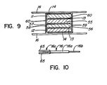
- a cross-section through one alternative form of filter is illustrated in Figure 9.
- a central plurality of stripe electrodes 57 extends between the two plates.
- Alternate stripe electrodes 57 extend to one side edge 58 of the plates, stopping short of the other side edges 59.
- the intervening stripe electrodes extend to side edge 59 and stop short of edge 58.
- Stripe connections 60 extend down the side edges 58 and 59 to interconnect top and bottom stripe electrodes alternately with central stripe electrodes 57.
- Other arrangements can be provided. It will be appreciated that the thickness of the ground planes 13 and central stripe electrodes 57 is very much exaggerated, in Figure 9, for clarity. In practice, these would be very thin and no difficulties would arise in forming the connections 60, and spanning any extremely thin gaps between the plates 11 and 55, 55 and 56 and 56 and 12.
- the terminal pins 16 can be of many different forms, depending upon the particular installation or assembly.
- the pins can be of male form both ends, female form both ends, male form one end and female the other end.
- One end can be male or female as desired and the other end be suitable for solder attachment or wire wrapping attachment of conductors.
- Figure 10 illustrates one form of pin 16 in which the central portion 16a is of rectangular cross-section, one end portion 16b is of circular cross-section and of male form, and the other end portion 16c is of female form with two arcuate legs 65 formed and spaced to accept a round male terminal part, for example a part similar to portion 16b.
- conductors are soldered directly on to the electrodes 14 at one end of each stripe. Pins can also be soldered to the stripes and project beyond the other ends of the stripes.
- conductors are soldered directly on to the electrodes 14 at one end of each stripe. Pins can also be soldered to the stripes and project beyond the other ends of the stripes.
- it can be arranged that as two connector parts are pushed together, in the filter element in one part slides between spaced contacts in the other part, contact being made directly between the contacts and the stripes as the connector is assembled.
- the overall dimensions of the filter element are set by connector parameters, for example terminal pin pitch and row spacing. Electrical characteristics can be adjusted by selection of materials for the dielectric members i.e. ceramic plates 11 and 12, and also by design of the electrode pattern.
- the filter element is particularly suitable for use in the 1-200MHz frequency range.
Landscapes
- Details Of Connecting Devices For Male And Female Coupling (AREA)
- Filters And Equalizers (AREA)
- Structure Of Telephone Exchanges (AREA)
- Coupling Device And Connection With Printed Circuit (AREA)
Applications Claiming Priority (2)
| Application Number | Priority Date | Filing Date | Title |
|---|---|---|---|
| CA432637 | 1983-07-18 | ||
| CA000432637A CA1198184A (fr) | 1983-07-18 | 1983-07-18 | Filtre electronique plan, et connecteur qui le renferme |
Publications (2)
| Publication Number | Publication Date |
|---|---|
| EP0132327A2 true EP0132327A2 (fr) | 1985-01-30 |
| EP0132327A3 EP0132327A3 (fr) | 1988-02-03 |
Family
ID=4125694
Family Applications (1)
| Application Number | Title | Priority Date | Filing Date |
|---|---|---|---|
| EP84304438A Withdrawn EP0132327A3 (fr) | 1983-07-18 | 1984-06-28 | Elément fltre électronique plan et connecteur incorporant un tel filtre |
Country Status (4)
| Country | Link |
|---|---|
| EP (1) | EP0132327A3 (fr) |
| JP (1) | JPS6039783A (fr) |
| KR (1) | KR900002889B1 (fr) |
| CA (1) | CA1198184A (fr) |
Cited By (4)
| Publication number | Priority date | Publication date | Assignee | Title |
|---|---|---|---|---|
| EP0169053A3 (en) * | 1984-07-16 | 1986-12-30 | Nippondenso Co., Ltd. | High frequency filter for electric instruments |
| EP0216389A3 (en) * | 1985-09-26 | 1987-12-16 | Nippondenso Co., Ltd. | High frequency filter assembly for electric instrument |
| EP0299162A3 (fr) * | 1987-07-15 | 1990-06-20 | Robert Bosch Gmbh | Connecteur multipolaire incorporé |
| EP0674363A3 (fr) * | 1994-01-13 | 1997-07-16 | Filtec Filtertechnologie Fur D | Connecteur multipoles avec agencement de filtre. |
Families Citing this family (2)
| Publication number | Priority date | Publication date | Assignee | Title |
|---|---|---|---|---|
| JPS6193570A (ja) * | 1984-10-13 | 1986-05-12 | 株式会社デンソー | 電子機器のためのコネクタ |
| JP2785309B2 (ja) * | 1989-03-30 | 1998-08-13 | 富士通株式会社 | コネクタ |
Family Cites Families (4)
| Publication number | Priority date | Publication date | Assignee | Title |
|---|---|---|---|---|
| BR7508698A (pt) * | 1975-01-08 | 1976-08-24 | Bunker Ramo | Conjunto de filtro para conector |
| US4144509A (en) * | 1977-01-12 | 1979-03-13 | Bunker Ramo Corporation | Filter connector |
| US4215326A (en) * | 1978-01-16 | 1980-07-29 | Amp Incorporated | Filtered adapter |
| US4296390A (en) * | 1980-04-21 | 1981-10-20 | Amp Incorporated | Solderless filter mounting for header assemblies |
-
1983
- 1983-07-18 CA CA000432637A patent/CA1198184A/fr not_active Expired
-
1984
- 1984-06-28 EP EP84304438A patent/EP0132327A3/fr not_active Withdrawn
- 1984-07-16 KR KR1019840004191A patent/KR900002889B1/ko not_active Expired
- 1984-07-17 JP JP59147027A patent/JPS6039783A/ja active Pending
Cited By (6)
| Publication number | Priority date | Publication date | Assignee | Title |
|---|---|---|---|---|
| EP0169053A3 (en) * | 1984-07-16 | 1986-12-30 | Nippondenso Co., Ltd. | High frequency filter for electric instruments |
| US4935710A (en) * | 1984-07-16 | 1990-06-19 | Nippondenso Co., Ltd. | High frequency filter for electric instruments |
| EP0216389A3 (en) * | 1985-09-26 | 1987-12-16 | Nippondenso Co., Ltd. | High frequency filter assembly for electric instrument |
| US4782310A (en) * | 1985-09-26 | 1988-11-01 | Nippondenso Co., Ltd. | High frequency filter assembly for electric instrument |
| EP0299162A3 (fr) * | 1987-07-15 | 1990-06-20 | Robert Bosch Gmbh | Connecteur multipolaire incorporé |
| EP0674363A3 (fr) * | 1994-01-13 | 1997-07-16 | Filtec Filtertechnologie Fur D | Connecteur multipoles avec agencement de filtre. |
Also Published As
| Publication number | Publication date |
|---|---|
| KR850000825A (ko) | 1985-03-09 |
| CA1198184A (fr) | 1985-12-17 |
| JPS6039783A (ja) | 1985-03-01 |
| EP0132327A3 (fr) | 1988-02-03 |
| KR900002889B1 (ko) | 1990-05-01 |
Similar Documents
| Publication | Publication Date | Title |
|---|---|---|
| EP0677213B1 (fr) | Systeme d'interconnexion | |
| US4695115A (en) | Telephone connector with bypass capacitor | |
| US6129592A (en) | Connector assembly having terminal modules | |
| US4932888A (en) | Multi-row box connector | |
| US5664968A (en) | Connector assembly with shielded modules | |
| US7008266B2 (en) | Mini DIN connector having a reduced height above a printed circuit board | |
| US6095872A (en) | Connector having terminals with improved soldier tails | |
| US5413491A (en) | Small form factor connectors with center ground plate | |
| US5860814A (en) | Electric connector for printed circuit board | |
| EP0918376A2 (fr) | Connecteurs modulaires | |
| US4917614A (en) | Electrical connector for surface mounting onto circuit boards | |
| US4589720A (en) | Planar electronic filter element and a connector embodying such a filter | |
| EP0709931A2 (fr) | Connecteur de bord de circuit monté en surface | |
| US6056559A (en) | Punched sheet coax header | |
| US6139368A (en) | Filtered modular connector | |
| US20080160839A1 (en) | Electrical interconnection with terminals in columns | |
| US5127838A (en) | Plated electrical connectors | |
| EP1044486A1 (fr) | Connecteur electrique blinde | |
| US5078609A (en) | Plural jack connector module | |
| EP0109297B1 (fr) | Eléments de contacts électriques et d'assemblages de connecteurs électriques | |
| EP0132327A2 (fr) | Elément fltre électronique plan et connecteur incorporant un tel filtre | |
| EP0724312B1 (fr) | Connecteur électrique avec un adaptateur de filtre à multiple position | |
| US6234847B1 (en) | Electrical connector having an insert module and a circuit board in contact with the insert module | |
| EP0171985A2 (fr) | Connecteurs empilables pour circuits imprimés et assemblages de circuits imprimés utilisant des connecteurs empilables | |
| JP2921248B2 (ja) | コネクタ |
Legal Events
| Date | Code | Title | Description |
|---|---|---|---|
| PUAI | Public reference made under article 153(3) epc to a published international application that has entered the european phase |
Free format text: ORIGINAL CODE: 0009012 |
|
| AK | Designated contracting states |
Designated state(s): DE FR GB |
|
| PUAL | Search report despatched |
Free format text: ORIGINAL CODE: 0009013 |
|
| AK | Designated contracting states |
Kind code of ref document: A3 Designated state(s): DE FR GB |
|
| 17P | Request for examination filed |
Effective date: 19880324 |
|
| 17Q | First examination report despatched |
Effective date: 19891005 |
|
| STAA | Information on the status of an ep patent application or granted ep patent |
Free format text: STATUS: THE APPLICATION IS DEEMED TO BE WITHDRAWN |
|
| 18D | Application deemed to be withdrawn |
Effective date: 19900216 |
|
| RIN1 | Information on inventor provided before grant (corrected) |
Inventor name: MIDDLEHURST, RICHARD JOHN Inventor name: SIMPSON, JOHN PAUL Inventor name: AUJLA, SHARANJIT SINGH |