EP0132334A2 - Thermoremanent-magnetisches Bilderzeugungsverfahren - Google Patents
Thermoremanent-magnetisches Bilderzeugungsverfahren Download PDFInfo
- Publication number
- EP0132334A2 EP0132334A2 EP84304564A EP84304564A EP0132334A2 EP 0132334 A2 EP0132334 A2 EP 0132334A2 EP 84304564 A EP84304564 A EP 84304564A EP 84304564 A EP84304564 A EP 84304564A EP 0132334 A2 EP0132334 A2 EP 0132334A2
- Authority
- EP
- European Patent Office
- Prior art keywords
- magnetic
- record medium
- nip
- areas
- magnetizing
- Prior art date
- Legal status (The legal status is an assumption and is not a legal conclusion. Google has not performed a legal analysis and makes no representation as to the accuracy of the status listed.)
- Withdrawn
Links
Images
Classifications
-
- G—PHYSICS
- G03—PHOTOGRAPHY; CINEMATOGRAPHY; ANALOGOUS TECHNIQUES USING WAVES OTHER THAN OPTICAL WAVES; ELECTROGRAPHY; HOLOGRAPHY
- G03G—ELECTROGRAPHY; ELECTROPHOTOGRAPHY; MAGNETOGRAPHY
- G03G19/00—Processes using magnetic patterns; Apparatus therefor, i.e. magnetography
- G03G19/005—Processes using magnetic patterns; Apparatus therefor, i.e. magnetography where the image is formed by selective demagnetizing, e.g. thermomagnetic recording
Definitions
- the present invention relates to thermoremanent magnetic imaging and more particularly to an energy-efficient thermoremanent magnetic imaging station in a magnetographic printer using a thermal printhead and pre-magnetization of the record medium to produce improved latent magnetic images which, when developed with magnetic toner, are capable of providing high density images.
- One important parameter of a ferromagnetic material affected by the temperature-induced phase change is a loss of remanent magnetization stored in the ferromagnetic material before it is heated.
- the material will show a magnetic field of a certain magnitude and polarity that is remanent or remains.
- the remanent magnetization is lost.
- the heating of a ferromagnetic material above its Curie temperature is used for erasing magnetization stored in a material.
- the heating of a ferromagnetic material beyond its Curie point and cooling it in the presence of a magnetic field is a method of recording a magnetization therein based upon the applied magnetic field.
- thermomagnetic recording or erasing with processes similar to these methods is known in the art.
- U.S. 3,555,556 and the background patents cited therein are illustrative of references that describe the recording of optical images on magnetic media. Not only have direct thermomagnetic copying processes been described in the art, but also those termed "reflexive.”
- U.S. Patent No. 3,698,005 and references cited therein describe a recording member for reflexive imaging where a magnetic material is heated beyond its Curie temperature by a flash procedure.
- Thermoremanent magnetic imaging is simply an imaging technique that creates a latent magnetic image on a ferromagnetic material that is usually, but not necessarily, coated on an insulating substrate.
- the image is created by locally heating portions of the coating material above the Curie temperature point to achieve a phase change in magnetic properties and simultaneously applying a magnetic field so that as the coating material cools in the presence of the applied magnetic field, the remanent magnetization from the applied field remains in the coating material, resulting in a latent magnetic image in the coating material.
- Such a latent magnetic image may be developed with magnetic toner, the toner transferred to appear in image configuration and fixed thereto for a permanent copy.
- U.S. 4,294,901 discloses a multi-layered substrate for thermoremanent magnetic imaging.
- a conductive stylus array provides current through the substrate to heat locally selected portions in image configuration to the Curie temperature of the substrate.
- a magnetic latent image is formed when the heated portion of the member is allowed to cool in an externally applied magnetic field at a strength of between 0.001 and 0.02T.
- the substrate is pre-magnetized and the background image areas of the substrate are heated to the Curie temperature. The substrate is thereafter cooled in the absence of any externally applied magnetic field.
- the latent image is developed by contacting the substrate containing the latent image with magnetic toner and transferring the developed image to a permanent sheet of, for example, paper and fixing the developed image thereto.
- U.S. 3,804,511 teaches the use of a tape having a record medium on the surface which is magnetizable and capable of forming an electrostatic image. After a latent electrostatic image is formed and the image on the recording medium developed with toner having both an electrostatically attractive component and a magnetic component, the side of the tape opposite to the one containing the developed image is subjected to a continuous AC magnetizing current which applies a uniform magnetic recording in the record medium through the tape. A latent magnetic image is formed in the record medium by applying a magnetic erasing signal to the tape from the side of the tape confronting the developed image through the toner image, so that the toner shields the record medium and only the non-image area of the recording medium is erased.
- a latent magnetic image corresponding to or duplicating the latent electrostatic image is formed. This enables multiple copies to be made from one latent image.
- the second and subsequent copies were obtained by developing the latent magnetic image with the same toner (that has a magnetic component) and transferring the developed image to paper without removing the latent magnetic image which is retained in the record medium until specifically erased by another magnetic erasing signal applied after the last developed image is transferred to paper.
- U.S. 4,032,923 discloses a thermoremanent magnetographic imaging apparatus which copies xerographically produced images from a slave web onto a magnetizable surface of a master web.
- the thermomagnetic transfer is produced by exposing the slave and master webs while in intimate contact to a single intense burst of radiation from a xenon lamp.
- the master web is pre-recorded in alternating patterns of magnetization by an AC recording head.
- the frequency at which the record head is gated by the alternating current source determines the final image resolution.
- the radiant energy from the lamp raises the temperature of the master web above its Curie point in the non-image areas, thus erasing the pre-magnetization pattern of alternating magnetic pole directions in the non-image areas.
- the remaining image is then developed by magnetic toner and transferred to a copy sheet.
- U.S. 4,343,008 discloses a method of making a magnetic imaging master capable of development with magnetic toner and transfer of the developed image many times.
- the master is made by pre-magnetizing the master and inserting it into a conventional typewriter where character images are typed on a backing layer of the master creating a right reading image therein.
- the master is then flash exposed to a xenon lamp which erases all pre-magnetized areas not shielded by the typed characters.
- U.S. 3,791,843 and U.S. 3,845,306 disclose method and apparatus, respectively, for thermomagnetic imaging. These cases disclose the use of particular compounds such as Fe Rh, as a coating on the magnetic record medium. Such compounds are antiferromagnetic at temperatures above and below a particular temperature known as the Neel temperature.
- the coated record medium is on a rotatable drum which is internally heated to its Neel temperature, and an original document is radiantly exposed on the record medium at an exposure station in the typical successive incremental fashion well known in the art.
- the radiant exposure source emits radiant energy which passes through the original document, impinging on the record medium.
- thermoremanent magnetic imaging device it is the object of this invention to reduce the energy usage of a thermoremanent magnetic imaging device by heating only the image areas of a pre-magnetized recording medium to its Curie point temperature in order to produce the latent magnetic image.
- a magnetic record medium is pre-magnetized in a uniform, in-plane fashion using permanent magnets.
- the pre-magnetized record medium is conveyed into a nip formed by a thermal printhead and a force-biased roller which urges the record medium into contact with the thermal printhead.
- a magnetizing field is provided having a strength of about 1/3 to 2/5 that of the pre-magnetizing magnet and having an opposite magnetizing direction. The magnetizing force of the magnetic field at the nip is not of sufficient strength to overcome the polarizing direction produced by the pre-magnetizing magnet.
- the thermal printhead heats the pixel areas of the record medium in image configuration above its Curie point
- the pre-magnetization is erased and replaced by that of the magnetic field at the nip as the heated region cools.
- the direction of the layer magnetization in the heated pixel areas is switched by the magnetic field at the nip.
- the pixel areas are allowed to cool in the magnetic field at the nip, thus, freezing the switched magnetization regions and setting up magnetic fringe fields between the regions of different magnetic direction, i.e., the pixel areas making up the latent image and the pre-magnetized background areas.
- the preceding and succeeding pixels produced by each thermal element in the thermal printhead are spaced so that each individual pixel causes a small fringe field to occur with the pre-magnetized background that will subsequently attract and hold magnetic toner during development of the latent magnetic image. If the pixels are allowed to group too closely together, the fringe field will occur on the outer periphery of the group and that part of the image area inside the group of pixels will not attract and hold magnetic toner, resulting in a hole or blank spot, which would reduce the quality of the final copy of the image.
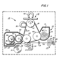
- thermoremanent magnetic imaging system generally designated by the numeral 10, incorporating a magnetic imaging station 12 configured to operate in accordance with the imaging process of the present invention, more fully described later with reference to Figures 2 and 3.
- the imaging system 10 includes a series of process stations through which a record medium 18 in the form of an endless belt mounted over rollers 41, 42 and 43 passes.
- a record medium 18 in the form of an endless belt mounted over rollers 41, 42 and 43 passes.
- various other configurations could be used equally as well such as, for example, one having a supply roll and a takeup roll which may be rewound when the supply is depleted.
- the record medium 18 proceeds past a development station 14, a transfer station 22, and a cleaning station 26 in the direction of arrow 29.
- the development, transfer and cleaning stations are typical stations well known in the magnetography field.
- a rotating brush or paddle wheel 15, housed in hopper 17, presents magnetic toner 16 onto the recording surface 19 of record medium 18.
- the toner is attracted and held by the latent magnetic image and is transferred to a permanent material 20, such as paper, at transfer station 22.
- the record medium proceeds past cleaning station 26, past a pre-magnetizing magnets 30 and back to the imaging station 12.
- the developed image is pressure transferred to the paper 20 at the transfer station 22.
- the paper is provided by supply roll 21 which is pulled through the transfer station via drive rolls 25 and through a toner fixing station 27 by drive rolls 29 where the toner image is permanently fixed to the paper moving in the direction of arrow 38.
- Cutter assembly 28 cuts the paper with the fixed images into separate sheets.
- the transfer station includes pressure roller 23 which is urged by adjustable spring 24 towards the record medium as the record medium moves around support roller 43. The paper is squeezed against the developed toner image between rollers 23 and 43 to effect the pressure transfer.
- An electrostatic transfer technique could also be used to effect transfer of toner image to the paper.
- the record medium is moved past the cleaning station 26 which removes any residual toner not transferred to the paper.
- a soft brush 32 housed in chamber 33 removes the residual toner from the record medium 18 and a single magnetic brush roll 34 is used to remove the toner from the brush.
- a conventional flicker bar 35 is arranged to assist in toner removal from the soft brush and a doctor blade 36 is used on the magnetic brush roll to remove the residual toner from the magnetic brush roll 34 into a collecting tray 37 if toner reclaiming is desired.
- a preferred choice for the record medium 18 is a magnetic tape having a chromium dioxide recording surface sold under the trade name Croyln (R) by the E.I. DuPont Company, Wilmington, Delaware.
- the Curie point of Crolyn is about 132°C, which is low enough to provide excellent results in a thermoremanent magnetic imaging environment.
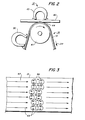
- thermoremanent magnetic imaging process which forms the present invention will now be described with reference to Figures 2 and 3.
- the record medium 18 having a magnetizable layer 19 moves around roller 41 in the direction of arrow 39.
- the roller 41 forms a nip 44 and urges the surface of the magnetizable layer of the recording medium into contact with a thermal printhead 40 (such as the one marketed by the Rohm Corporation under the designation Rohm Kh-106-6, or a 300 spi thermal printer sold by the Mitsubishi Electric Corporation of Japan under the designation S 215-12).
- the biasing force of the roller 41 may be varied from 0.0018 to 0.11 kg/mm, but the preferred range is 0.018 to 0.07 kg/mm.
- the magnetizable surface of the recording medium is pre-magnetized by permanent magnet 30 having pre-magnetization field of between 0.06 and 0.4T; the preferred field strength is about 0.16T.
- the thermal elements of the printhead are activated by the selective application of a voltage across the individual heating element according to data signals received from a controller (not shown) to heat, in image configuration, small areas or pixels of the magnetizable surface above the Curie point of the magnetizable surface in the presence of a magnetizing field produced by permanent magnet 45.
- Magnet 45 has a polarity opposite to that produced by pre-magnetizing magnet 30.
- the magnetization field at the nip produced by magnet 45 should be below the coercivity of the magnetizable layer 19 and, in the preferred embodiment, limited to 1/3 to 2/5 that of the pre-magnetizing magnet 30. Therefore, the magnetic field at the nip is about 0.05T or less.
- the field strength of magnet 45 is too weak to have an appreciable affect on the pre-magnetized recording medium, except in areas heated above the record medium Curie point.
- the thermal elements of the printhead When the thermal elements of the printhead are activated by the data signals to form pixels in image configuration, the pixels on the magnetizable surface of the recording medium are heated to the Curie point of the magnetizable surface. This heating is done at the nip so that the pre-magnetization in the pixels is erased and the magnetizing field of magnet 45 is able to induce a magnetism in the pixels having a magnetic polarity opposite to that of the pre-magnetized background area.
- the activation or heating time of the thermal elements in conjunction with the surface speed of the record medium enables the heated pixel areas to cool while still in the magnetic field at the nip, thus fixing the switched magnetization regions in the pixels areas, as seen in Figure 3.
- the opposing magnetization 48 in the pre-magnetized background area 47 and the pixel regions 46 form fringe fields which attract and hold magnetic toner during subsequent development of the latent magnetic image which is formed by the pixels 46.
- the interburn time that is the time between thermal element activation, is optionally of a duration of between 1-13 ms which assures appropriate spacings between succeeding pixels. As discussed above, this is important for copy quality, because if the pixel magnetization regions are too close together the fringe fields occur only around the periphery of a group of pixels. This leaves areas which weakly attract and hold toner, even though it is part of the image. Therefore, if this situation exists, blank spaces may be visible in the final copy.
- the moving magnetizable surface of the recording medium must be heated to the Curie point in image configuration composed of separate pixels and cooled in the presence of a fixed magnetic field located at the nip.
- the erased pre-magnetization will be induced again in the pixels by the surrounding pre-magnetized area if the pixels are left with zero magnetization.
- the magnetization of the pixel regions will not be switched if the pixel area cools below the Curie point outside the opposing magnetic field of the nip. If the voltage which activates the printhead thermal elements is too large the pixel is heated much beyond the Curie point and takes too long to cool, so that the moving record medium may be outside the opposing fixed field when it cools.
- the present invention provides a method and apparatus for increasing the energy efficiency of a thermal printhead used in a thermoremanent magnetic imaging environment, while improving the effectiveness of the resultant latent magnetic image in a magnetic recording produced thereby so that the latent magnetic image attracts and holds magnetic toner in an efficient manner.
- the magnetic record medium is pre-magnetized prior to entering a nip formed between a commercially available thermal printhead, heating pixels of the record medium to the Curie point in image configuration while in a magnetic field opposite in polarity to that of the pre-magnetization, and allowing the pixels to cool in the magnetic field to switch the magnetic poles within the pixels to obtain fringe fields between the pixels and the pre-magnetized background.
- the magnetic field at the nip has a strength small enough not to switch the magnetic poles of the background area, viz., 1/3 to 2/5 the coercivity of that of the pre-magnetization.
- Optimum values of the parameters for the thermomagnetic imaging system have been disclosed above.
Landscapes
- Physics & Mathematics (AREA)
- General Physics & Mathematics (AREA)
- Printers Or Recording Devices Using Electromagnetic And Radiation Means (AREA)
Applications Claiming Priority (2)
| Application Number | Priority Date | Filing Date | Title |
|---|---|---|---|
| US06/515,720 US4531137A (en) | 1983-07-20 | 1983-07-20 | Thermoremanent magnetic imaging method |
| US515720 | 1990-04-27 |
Publications (2)
| Publication Number | Publication Date |
|---|---|
| EP0132334A2 true EP0132334A2 (de) | 1985-01-30 |
| EP0132334A3 EP0132334A3 (de) | 1985-04-17 |
Family
ID=24052466
Family Applications (1)
| Application Number | Title | Priority Date | Filing Date |
|---|---|---|---|
| EP84304564A Withdrawn EP0132334A3 (de) | 1983-07-20 | 1984-07-04 | Thermoremanent-magnetisches Bilderzeugungsverfahren |
Country Status (4)
| Country | Link |
|---|---|
| US (1) | US4531137A (de) |
| EP (1) | EP0132334A3 (de) |
| JP (1) | JPS6042782A (de) |
| CA (1) | CA1216064A (de) |
Families Citing this family (5)
| Publication number | Priority date | Publication date | Assignee | Title |
|---|---|---|---|---|
| DE3477430D1 (en) * | 1984-02-15 | 1989-04-27 | Fuji Xerox Co Ltd | Magnetic recording apparatus |
| JPS6120077A (ja) * | 1984-07-06 | 1986-01-28 | Fuji Xerox Co Ltd | 熱磁気記録装置 |
| FR2588406B1 (fr) * | 1985-10-04 | 1994-03-25 | Thomson Csf | Tete d'enregistrement thermomagnetique et procede de realisation |
| US4770413A (en) * | 1987-04-27 | 1988-09-13 | Mba Healthcare Products, Inc. | Breathing exercise device |
| US6785073B2 (en) | 2000-06-14 | 2004-08-31 | Seagate Technology Llc | Identification and cancellation of cage frequency in a hard disc drive |
Family Cites Families (19)
| Publication number | Priority date | Publication date | Assignee | Title |
|---|---|---|---|---|
| BE672018A (de) * | 1964-11-09 | 1966-05-09 | ||
| US3521294A (en) * | 1967-03-13 | 1970-07-21 | Ampex | Magneto thermal recording process and apparatus |
| NL6905677A (de) * | 1969-04-12 | 1970-10-14 | ||
| US3698005A (en) * | 1970-05-15 | 1972-10-10 | Du Pont | Dry magnetic copying process |
| US3804511A (en) * | 1970-07-29 | 1974-04-16 | Pelorex Corp | Method and apparatus utilizing magnetic storage for transferring graphical information |
| DE2054117A1 (de) * | 1970-11-04 | 1972-05-10 | Agfa Gevaert Ag | Magnetisches Abbildungsverfahren und Vorrichtung zur Durchführung des Verfahrens |
| US3845306A (en) * | 1970-11-04 | 1974-10-29 | Agfa Gevaert Ag | Thermomagnetic imaging apparatus |
| DE2131068A1 (de) * | 1971-06-23 | 1973-01-11 | Nortron Hermann Koehler Elek K | Thermischer schreibkopf |
| US3935578A (en) * | 1974-02-25 | 1976-01-27 | Eastman Kodak Company | Thermo-magnetic image recording methods and apparatus |
| US4032923A (en) * | 1975-11-12 | 1977-06-28 | Xerox Corporation | Thermomagnetic imaging apparatus |
| JPS5262029A (en) * | 1975-11-15 | 1977-05-23 | Hitachi Ltd | Thermal recording device |
| US4216282A (en) * | 1977-03-18 | 1980-08-05 | E. I. Du Pont De Nemours And Company | AC corona to remove background from the imaging member of a magnetic copier |
| CH621421A5 (en) * | 1976-03-31 | 1981-01-30 | Du Pont | Magnetographic dry copying process and device for carrying it out |
| US4442441A (en) * | 1980-02-19 | 1984-04-10 | Fuji Xerox Co., Ltd. | Magnetic recording device |
| US4343008A (en) * | 1980-07-28 | 1982-08-03 | Xerox Corporation | Method for creating magnetic masters |
| JPS5764274A (en) * | 1980-10-07 | 1982-04-19 | Fuji Xerox Co Ltd | Magnetic latent image forming device |
| JPS5784871A (en) * | 1980-11-17 | 1982-05-27 | Fuji Xerox Co Ltd | Heat transfer recorder |
| US4294901A (en) * | 1980-11-03 | 1981-10-13 | Xerox Corporation | Thermoremanent magnetic imaging member and system |
| JPS5867474A (ja) * | 1981-10-19 | 1983-04-22 | Toshiba Corp | サ−マルヘッドの製造方法 |
-
1983
- 1983-07-20 US US06/515,720 patent/US4531137A/en not_active Expired - Fee Related
-
1984
- 1984-06-14 CA CA000456625A patent/CA1216064A/en not_active Expired
- 1984-07-04 EP EP84304564A patent/EP0132334A3/de not_active Withdrawn
- 1984-07-10 JP JP59143181A patent/JPS6042782A/ja active Pending
Also Published As
| Publication number | Publication date |
|---|---|
| EP0132334A3 (de) | 1985-04-17 |
| JPS6042782A (ja) | 1985-03-07 |
| CA1216064A (en) | 1986-12-30 |
| US4531137A (en) | 1985-07-23 |
Similar Documents
| Publication | Publication Date | Title |
|---|---|---|
| US3526191A (en) | Duplicating process employing magnetic developer material | |
| US3987491A (en) | Latent magnetic image transfer apparatus | |
| US3965478A (en) | Multicolor magnetographic printing system | |
| US2970299A (en) | Electrographic recording with magnetic material | |
| US4531137A (en) | Thermoremanent magnetic imaging method | |
| US4233382A (en) | Electrostatic transfer of magnetically held toner images | |
| GB2047172A (en) | Thermomagnetic recording fascimile receiver | |
| US4543586A (en) | Magnetizing apparatus for a magnetographic printer | |
| US3993484A (en) | Electrostatic-magnetic method of transferring graphical information | |
| US4216282A (en) | AC corona to remove background from the imaging member of a magnetic copier | |
| CA1065951A (en) | Donor transfer of magnetic toner | |
| CA1094631A (en) | Technique of character generation on magnetic tapes | |
| US4329694A (en) | AC Corona to remove background from the transfer member of a thermomagnetic copier | |
| US4458252A (en) | Magnetic image recording device | |
| CA1107343A (en) | Ac corona to remove background from the transfer member of a thermomagnetic copier | |
| US4395470A (en) | Process of forming magnetic latent images | |
| US4135195A (en) | Magnetographic printing apparatus | |
| US4701768A (en) | Thermo-magnetic recording device | |
| CA1107342A (en) | Electrostatic transfer of magnetically held toner images | |
| US4686933A (en) | Magnetic recording image developing apparatus | |
| JPS5811178A (ja) | 磁気記録方法 | |
| US4558327A (en) | Magnetic copying method and apparatus | |
| JPH0348881A (ja) | 記録装置 | |
| JPH0375783A (ja) | 熱磁気記録装置 | |
| JPS5835575A (ja) | 磁気潜像部分消去方法 |
Legal Events
| Date | Code | Title | Description |
|---|---|---|---|
| PUAI | Public reference made under article 153(3) epc to a published international application that has entered the european phase |
Free format text: ORIGINAL CODE: 0009012 |
|
| AK | Designated contracting states |
Designated state(s): DE FR GB IT |
|
| PUAL | Search report despatched |
Free format text: ORIGINAL CODE: 0009013 |
|
| AK | Designated contracting states |
Designated state(s): DE FR GB IT |
|
| STAA | Information on the status of an ep patent application or granted ep patent |
Free format text: STATUS: THE APPLICATION IS DEEMED TO BE WITHDRAWN |
|
| 18D | Application deemed to be withdrawn |
Effective date: 19851218 |
|
| RIN1 | Information on inventor provided before grant (corrected) |
Inventor name: HERMANSON, HERMAN ALVIN Inventor name: DREWS, REINHOLD ELDOR Inventor name: FISHER, ALMON PRESTON Inventor name: POND, STEPHEN FULLERTON |