EP0132342B1 - Verfahren und Einrichtung zur Kontrolle des Spektrums eines Lichtbündels - Google Patents
Verfahren und Einrichtung zur Kontrolle des Spektrums eines Lichtbündels Download PDFInfo
- Publication number
- EP0132342B1 EP0132342B1 EP84304682A EP84304682A EP0132342B1 EP 0132342 B1 EP0132342 B1 EP 0132342B1 EP 84304682 A EP84304682 A EP 84304682A EP 84304682 A EP84304682 A EP 84304682A EP 0132342 B1 EP0132342 B1 EP 0132342B1
- Authority
- EP
- European Patent Office
- Prior art keywords
- light beam
- aperture
- movement
- profile
- image
- Prior art date
- Legal status (The legal status is an assumption and is not a legal conclusion. Google has not performed a legal analysis and makes no representation as to the accuracy of the status listed.)
- Expired
Links
Images


Classifications
-
- G—PHYSICS
- G01—MEASURING; TESTING
- G01J—MEASUREMENT OF INTENSITY, VELOCITY, SPECTRAL CONTENT, POLARISATION, PHASE OR PULSE CHARACTERISTICS OF INFRARED, VISIBLE OR ULTRAVIOLET LIGHT; COLORIMETRY; RADIATION PYROMETRY
- G01J3/00—Spectrometry; Spectrophotometry; Monochromators; Measuring colours
- G01J3/12—Generating the spectrum; Monochromators
- G01J3/14—Generating the spectrum; Monochromators using refracting elements, e.g. prisms
-
- G—PHYSICS
- G01—MEASURING; TESTING
- G01J—MEASUREMENT OF INTENSITY, VELOCITY, SPECTRAL CONTENT, POLARISATION, PHASE OR PULSE CHARACTERISTICS OF INFRARED, VISIBLE OR ULTRAVIOLET LIGHT; COLORIMETRY; RADIATION PYROMETRY
- G01J3/00—Spectrometry; Spectrophotometry; Monochromators; Measuring colours
- G01J3/46—Measurement of colour; Colour measuring devices, e.g. colorimeters
-
- G—PHYSICS
- G01—MEASURING; TESTING
- G01J—MEASUREMENT OF INTENSITY, VELOCITY, SPECTRAL CONTENT, POLARISATION, PHASE OR PULSE CHARACTERISTICS OF INFRARED, VISIBLE OR ULTRAVIOLET LIGHT; COLORIMETRY; RADIATION PYROMETRY
- G01J3/00—Spectrometry; Spectrophotometry; Monochromators; Measuring colours
- G01J3/12—Generating the spectrum; Monochromators
- G01J2003/1278—Mask with spectral selection
-
- G—PHYSICS
- G01—MEASURING; TESTING
- G01J—MEASUREMENT OF INTENSITY, VELOCITY, SPECTRAL CONTENT, POLARISATION, PHASE OR PULSE CHARACTERISTICS OF INFRARED, VISIBLE OR ULTRAVIOLET LIGHT; COLORIMETRY; RADIATION PYROMETRY
- G01J3/00—Spectrometry; Spectrophotometry; Monochromators; Measuring colours
- G01J3/46—Measurement of colour; Colour measuring devices, e.g. colorimeters
- G01J3/50—Measurement of colour; Colour measuring devices, e.g. colorimeters using electric radiation detectors
- G01J3/501—Colorimeters using spectrally-selective light sources, e.g. LEDs
Definitions
- the invention relates to colour scanning apparatus.
- a colour image such as a transparency
- colour image scanning There are a number of applications where it is desirable to be able to control accurately the spectral components of a light beam and one particularly important application is that of colour image scanning.
- a colour image such as a transparency
- Such apparatus is embodied in our Crosfield Magnascan 600 series.
- a further problem with these systems is that the distribution of wavelength in space is not linear since the refractive index of the dispersing medium tends to vary with wavelength. This makes the method difficult to apply to other scanning applications, where frequent changes in spectral content are required.
- colour scanning apparatus comprises means for generating a collimated light beam; means for dispersing the collimated beam; a mask including an aperture, comprising a slit, the size of which is such that a portion of the dispersed beam passes through the aperture in use; and movement means for causing relative transverse movement between the light beam and the aperture, the apparatus further comprising a memory for storing in use a profile of the relative transverse movement between the light beam and the aperture required to obtain a desired spectral response in the transmitted light beam, characterised in that the movement means is responsive to the stored profile to cause relative transverse movement in accordance with the stored profile, and that the apparatus comprises a linear detector array which is exposed to the light beam transmitted through the aperture after the light beam has passed through an image, and control means for discharging the linear detector array at predetermined times during relative movement between the slit and the dispersed light beam whereby the transmittance of a line of the image to light beams of different spectral content is determined.
- the movement means comprises a galvanometer having a spindle linked to the mask, the spindle moving in response to control signals corresponding to the profile stored in the memory.
- a galvanometer is convenient since it comprises an instrument which has an accurate response to an applied signal.
- the size of the slit may also be varied to provide even more accurate control of the spectral components of the light beam.
- the speed of movement of the aperture relatively to the light beam can be altered to achieve the same effect.
- a computer which is programmed to simulate the light beam and the aperture during relative transverse movement therebetween in response to a test profile, the apparatus further comprising display means for displaying the spectral response of the transmitted light beam corresponding to the test profile. The operator can then review the displayed spectral response and if it is not satisfactory he can alter the test profile and cause the computer to simulate the light beam and the aperture in response to the revised profile.
- the display means comprises a device for graphically illustrating the spectral response.
- control means additionally causes relative movement between the image and the beam impinging on the image after the image has been exposed to the desired spectral components and while the dispersed light beam and the aperture return to their initial relative position under the control of the movement means.
- This arrangement enables very fast scanning to be carried out with the image being moved so that the next line is exposed while the dispersed light beam and the aperture return to their initial relative positions.
- the linear detector array may be discharged.
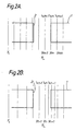
- FIG. 1 illustrates a mask 1 having an aperture 2 with a width W.
- the vertical lines in the Figures illustrate schematically the positions of typical wavelengths across a dispersed light beam.
- Figure 1A illustrates the wavelengths ( ⁇ m ) at equal spatial separations (y m ).
- ⁇ m - ⁇ m-1 will not equal ⁇ m+1 - ⁇ m . This is because the dispersion of a previously collimated light beam depends on the geometry and refractive index of the dispersing medium, such as a prism, and varies non-linearly with wavelength.
- Figure 1A should be contrasted with Figure 1B which illustrates the positions of wavelengths which are equally spaced in wavelength but, as has just been mentioned, will not necessarily be equally spaced in distance. These wavelengths are labelled ⁇ n and are positioned at y " . Thus, in Figure 1B, y n -y n-1 will not in general equal y n+1 -y n .
- a third domain, time, is required to calculate where the edges of the aperture 2 are as the mask 1 moves across the dispersed beam. This movement can be seen by comparing Figure 1 with Figures 2 and 3.
- Figures 1A and 1B illustrate the mask 1 with its right hand edge positioned at the beginning of the wavelength band centred on ⁇ m
- Figures 2A and 2B illustrate the mask 1 in an intermediate position after movement to the right as seen in the drawings
- Figures 3A and 3B illustrate the mask 1 with the left hand edge of the aperture 2 havng just left the waveband centred on A m .
- a function generator such as a suitably programmed microcomputer, then determines the position, y L , of the centre of the aperture 2 relatively to an initial position y 1 at a number of different times t L separated by equal time periods over a cycle period ⁇ . This can be achieved in two ways. The simplest method is for the function generator to provide a listing, for example as shown in the table below.
- a typical time interval between successive times t L is 1 millisecond.
- the function generator can determine a power law relating the position of the centre of the aperture 2 with time between successive pairs of break points q.
- the next stage is to calculate the effective charge accumulation time At m at each position y m .
- This is simply the time for which any particular bandwidth in the spatial domain is visible through the aperture 2. This corresponds to the time for the aperture 2 to move from the position shown in Figure 1A to the position shown in Figure 3A where the bandwidth is defined as y m ⁇ 1 2 ⁇ y m .
- the effective charge accumulation time can be calculated in a straight forward manner.
- the ratio of this charge accumulation time (At m ) to the overall cycle time ( T ) is the ratio of photo-electrons actually generated in the aperture scan to those it is possible to generate without the obstruction. That is:
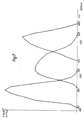
- ⁇ n( ⁇ n ) is the spectral response of the system expressed by the number of detected photo-electrons at equal wave-length intervals. This is illustrated in Figure 7.
- Figure 4 illustrates apparatus for use in colour scanning apparatus.
- This comprises a light source 3, for example a quartz halogen filament lamp, backed by a reflector 4.
- a light source 3 for example a quartz halogen filament lamp, backed by a reflector 4.
- Light from the source 3 passes through a condenser lens 5 and a collimator slit 6.
- the slit 6 lies in the front focal plane of a collimator lens 7 which thus generates a collimated light beam 8 which enters a dispersing prism 9.
- the dispersed light beam leaving the dispersing prism 9 passes through a telescope objective lens 10 and forms a continuous spectrum in the plane of a spectral limit slit 11.
- the spectral limit slit 11 is adjustable so that unwanted infra-red and ultra-violet wavelengths are cut off and all wanted wavelengths are transmitted.
- the mask 1 Downstream of the spectral limit slit 11 is positioned the mask 1 at the spectral image plane of the slit 6.
- the mask 1 has a central slit 2 extending vertically into the paper in Figure 4.
- the mask 1 is mounted to an arm 12 fixed to a spindle 13 of a galvanometer 14 ( Figure 5).
- a suitable galvanometer is a Model G310 sold by General Scanning Inc.
- the galvanometer 14 is connected to an EPROM 14' which stores a previously generated profile (to be described below) and is controlled in use via the EPROM to cause movement of the spindle 13 into and out of the paper as shown in Figure 5 in accordance with the stored profile.
- movement of the mask 1 is in a direction transverse to the light beam as indicated by an arrow 15.
- any other suitable means may be used to move the mask 1 but this is preferably electro-mechanical, for example, a load speaker coil.
- the position of the slit 2 is controlled so that only a portion of the light beam passing through the slit 11 will be transmitted through the slit 2 and that portion has a known spectral composition such as predominately red, predominately green, and predominately blue in sequence.
- the light beam then enters a second collimator 16, a dispersion prism 17, and an objective lens 18 which together form an optical inversion of the lenses 7, 10 and the prism 9.
- an undispersed beam of known spectral composition leaves the objective lens 18 and is reflected by a mirror 19 through a condenser system 20 to a film holder 21.
- the prism 17 may be omitted to leave a dispersed beam.
- a transparency 22 is sandwiched within the film holder 21 so that an undispersed image of the original collimator slit 6 will be formed at the film holder 21 to expose a line of the image on the transparency 22.
- the condenser system 20 reforms an image of the light source 3 at the pupil of an imaging les 23 and the imaging lens 23 relays the illuminated line of the image of the transparency 22 onto a detector array 24.
- the detector array 24 comprises a CCD array which has 3456 elements closely spaced in a straight line extending into the paper as seen in the drawing. A transparency of about 5.5 cmx5.5 cm is provided.
- the method of operation of the detector array 24 is such that a charge is accumulated at each detector element during the time period that a line of the image of the transparency 22 is exposed to the light beam, this charge being dependent on the number of photo-electrons of light energy falling on the detector element during that time.
- the charge pattern is discharged and the signals from the individual elements are read off by conventional means (not shown). The next set of charge signals are then accumulated.
- a computer simulation of the light beam transmitted from the prism 9 and of the mask 1 is carried out.
- the simulation may conveniently be provided by the computer 28 which is suitably programmed with the algorithms previously set out.
- the computer may comprise a D.E.C. PDP11 with the RSX operating system.
- data such as the size of the prism 9, the prism angle and glass type together with the size of the slit 2 and its thickness are input by an operator to enable the distribution of wavelengths in the wavelength domain to be calculated.
- the computer 28 then converts this information into the spatial domain. Subsequently, a profile of the position of the slit 2 relatively to the dispersed light beam is read into the computer.
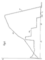
- Such a profile is illustrated graphically by a line 25 in Figure 6.
- a line 26 represents the differential of the line 25 and thus represents the velocity of the slit 2 relatively to the light beam as a function of time.
- This second line 26 is generated to ensure the capabilities of the galvanometer 14 are not exceeded.
- the computer can determine the spectral response of the transmitted light beam during movement of the slit across the dispersed beam in accordance with the profile.
- An example of such a response is illustrated graphically in Figure 7.
- the curves shown in Figure 7 have been generated by calculating the total number of photo-electrons transmitted in 10 nm wavelength bands.
- the galvanometer 14 is controlled by the EPROM 14' to cause the slit 2 to traverse the dispersed beam with the mask 1 following the determined profile so that the transparency 22 is sequentially illuminated by light beams having wavelengths centred at about 460, 530, and 620 nm successively.
- the computer 28 causes the array 24 to discharge to a conventional store at times of 24 ms, 36 ms and 48 ms from the start of the pass, the first two of thse times corresponding to the transition times between the light beams.
- the EPROM 14' causes the galvanometer to fly back to its initial position.
- the film holder 21 is moved by means not shown to the right or left as seen in the drawing under control of the computer 28 so that the next adjacent line of the image can be exposed. The process is then repeated until the entire transparency 22 is scanned.
- the width W of the slit 2 is 0.2 mm and the thickness of the mask is 3.0 mm.
Landscapes
- Physics & Mathematics (AREA)
- Spectroscopy & Molecular Physics (AREA)
- General Physics & Mathematics (AREA)
- Facsimile Scanning Arrangements (AREA)
- Mechanical Light Control Or Optical Switches (AREA)
- Microscoopes, Condenser (AREA)
Claims (5)
Applications Claiming Priority (2)
| Application Number | Priority Date | Filing Date | Title |
|---|---|---|---|
| GB838319798A GB8319798D0 (en) | 1983-07-22 | 1983-07-22 | Controlling light beam spectrum |
| GB8319798 | 1983-07-22 |
Publications (3)
| Publication Number | Publication Date |
|---|---|
| EP0132342A2 EP0132342A2 (de) | 1985-01-30 |
| EP0132342A3 EP0132342A3 (en) | 1986-06-04 |
| EP0132342B1 true EP0132342B1 (de) | 1989-09-20 |
Family
ID=10546125
Family Applications (1)
| Application Number | Title | Priority Date | Filing Date |
|---|---|---|---|
| EP84304682A Expired EP0132342B1 (de) | 1983-07-22 | 1984-07-09 | Verfahren und Einrichtung zur Kontrolle des Spektrums eines Lichtbündels |
Country Status (5)
| Country | Link |
|---|---|
| US (1) | US4660975A (de) |
| EP (1) | EP0132342B1 (de) |
| JP (1) | JPS6066225A (de) |
| DE (1) | DE3479829D1 (de) |
| GB (1) | GB8319798D0 (de) |
Families Citing this family (17)
| Publication number | Priority date | Publication date | Assignee | Title |
|---|---|---|---|---|
| GB9002327D0 (en) * | 1990-02-02 | 1990-04-04 | Univ Sheffield | Optical elements |
| US5285254A (en) * | 1991-03-25 | 1994-02-08 | Richard J De Sa | Rapid-scanning monochromator with moving intermediate slit |
| JPH04332830A (ja) * | 1991-05-08 | 1992-11-19 | Takayama:Kk | 光検出装置 |
| GB9214556D0 (en) * | 1992-07-09 | 2004-02-04 | Qinetiq Ltd | Optical filtering device |
| US5515182A (en) * | 1992-08-31 | 1996-05-07 | Howtek, Inc. | Rotary scanner |
| US5424827A (en) * | 1993-04-30 | 1995-06-13 | Litton Systems, Inc. | Optical system and method for eliminating overlap of diffraction spectra |
| US20010046088A1 (en) | 1994-02-14 | 2001-11-29 | Naoto Sano | Exposure apparatus and device manufacturing method using the same |
| US6038076A (en) * | 1997-12-03 | 2000-03-14 | Noran Instruments, Inc. | Wavelength selection, multiplexing and demultiplexing method and apparatus |
| US6166373A (en) * | 1998-07-21 | 2000-12-26 | The Institute For Technology Development | Focal plane scanner with reciprocating spatial window |
| FR2788137B1 (fr) * | 1998-12-31 | 2002-06-07 | Architecture Traitement D Imag | Dispositif a rejet spectral de formation d'une image sur un capteur optique |
| DE19950692A1 (de) * | 1999-10-15 | 2001-04-19 | Zeiss Carl Jena Gmbh | Anordnung zur wellenlängenabhängigen Einstellung von Lichtstrahlung |
| DE10033457A1 (de) * | 2000-07-10 | 2002-01-24 | Bayer Ag | Transmissionsspektroskopische Vorrichtung für Behälter |
| DE10231667A1 (de) * | 2002-07-12 | 2004-01-22 | Olympus Biosystems Gmbh | Beleuchtungsvorrichtung und optische Objektuntersuchungseinrichtung |
| US8094195B2 (en) * | 2006-12-28 | 2012-01-10 | Flextronics International Usa, Inc. | Digital camera calibration method |
| WO2009115945A1 (en) * | 2008-03-20 | 2009-09-24 | Koninklijke Philips Electronics N.V. | Photo-detector and method of measuring light |
| US20100321506A1 (en) * | 2009-03-02 | 2010-12-23 | Wei Li | Calibration techniques for camera modules |
| JP6955932B2 (ja) * | 2017-08-25 | 2021-10-27 | 株式会社ディスコ | レーザービームプロファイラユニット及びレーザー加工装置 |
Family Cites Families (9)
| Publication number | Priority date | Publication date | Assignee | Title |
|---|---|---|---|---|
| US3314327A (en) * | 1961-12-13 | 1967-04-18 | Honeywell Inc | Colorimeter employing tristimulus values |
| US3561872A (en) * | 1965-02-22 | 1971-02-09 | Polska Akademia Nauk Instytut | Electronic spectrophotometer |
| US3907430A (en) * | 1973-08-13 | 1975-09-23 | Northrop Corp | Optical bandpass filter |
| US3868499A (en) * | 1974-03-25 | 1975-02-25 | Gca Corp | Spectrometric apparatus |
| US4015130A (en) * | 1975-10-07 | 1977-03-29 | The United States Of America | Method and apparatus for monitoring optical radiation |
| US4165180A (en) * | 1977-06-17 | 1979-08-21 | Canadian Instrumentation And Research Limited | Automatic computing color meter |
| US4225233A (en) * | 1978-02-02 | 1980-09-30 | The Trustees Of Boston University | Rapid scan spectrophotometer |
| US4235518A (en) * | 1978-10-04 | 1980-11-25 | The United States Of America As Represented By The United States Department Of Energy | High efficiency laser spectrum conditioner |
| DE3005352C2 (de) * | 1980-02-13 | 1984-02-02 | Jürgen Ing.(grad.) 7400 Tübingen Maaßen | Optische Anordnung zum Erzeugen von zeitlich aufeinanderfolgenden Meßstrahlenbündeln unterschiedlicher Wellenlänge |
-
1983
- 1983-07-22 GB GB838319798A patent/GB8319798D0/en active Pending
-
1984
- 1984-07-09 EP EP84304682A patent/EP0132342B1/de not_active Expired
- 1984-07-09 DE DE8484304682T patent/DE3479829D1/de not_active Expired
- 1984-07-13 US US06/630,605 patent/US4660975A/en not_active Expired - Lifetime
- 1984-07-20 JP JP59149800A patent/JPS6066225A/ja active Granted
Also Published As
| Publication number | Publication date |
|---|---|
| GB8319798D0 (en) | 1983-08-24 |
| EP0132342A3 (en) | 1986-06-04 |
| DE3479829D1 (en) | 1989-10-26 |
| JPS6066225A (ja) | 1985-04-16 |
| US4660975A (en) | 1987-04-28 |
| JPH046925B2 (de) | 1992-02-07 |
| EP0132342A2 (de) | 1985-01-30 |
Similar Documents
| Publication | Publication Date | Title |
|---|---|---|
| EP0132342B1 (de) | Verfahren und Einrichtung zur Kontrolle des Spektrums eines Lichtbündels | |
| US4060327A (en) | Wide band grating spectrometer | |
| US4254337A (en) | Infrared interference type film thickness measuring method and instrument therefor | |
| US3927944A (en) | Spectrophotometer | |
| US4165180A (en) | Automatic computing color meter | |
| US4563090A (en) | Grating spectrometer | |
| US4520388A (en) | Optical signal projector | |
| DE68921249T2 (de) | Mikroskop-Spektralgerät. | |
| US3922089A (en) | Apparatus and method for the uniform separation of spectral orders | |
| US4705396A (en) | Image monochromator | |
| DE2312368A1 (de) | Optische messeinrichtung | |
| JPS634650B2 (de) | ||
| White et al. | Construction of a Double Beam Recording Infra-Red Spectrophotometer | |
| EP0340437A2 (de) | Apparat und Verfahren zur Messung dunkler und heller Spiegelungen eines Bahnmaterials | |
| DE2602158B2 (de) | ||
| US4448486A (en) | Varying bandpass of optical spatial filter by rotating mirrors having changing reflectivity | |
| GB2096792A (en) | Double monochromator using a concave rotatable diffraction grating | |
| US4391523A (en) | Scannable detector system for echelle grating spectrometers | |
| DE3889464T2 (de) | Fotografisches kopiergerät. | |
| US5506656A (en) | Method of and apparatus for measuring the optical density of a photographic negative | |
| DE3730257A1 (de) | Messgeraet fuer spektralcharakteristiken einer laserstrahlung | |
| US4172637A (en) | Common beam aperture for dual beam spectrophotometers | |
| US3490848A (en) | Spectral grating apparatus | |
| RU2025657C1 (ru) | Устройство для контроля толщины пленок многослойного оптического покрытия в процессе его нанесения осаждением в вакуумной камере | |
| EP0571714A2 (de) | Verbesserungen in oder bezüglich der Messung des Krümmungsradius einer Fläche |
Legal Events
| Date | Code | Title | Description |
|---|---|---|---|
| PUAI | Public reference made under article 153(3) epc to a published international application that has entered the european phase |
Free format text: ORIGINAL CODE: 0009012 |
|
| AK | Designated contracting states |
Designated state(s): DE GB |
|
| PUAL | Search report despatched |
Free format text: ORIGINAL CODE: 0009013 |
|
| AK | Designated contracting states |
Kind code of ref document: A3 Designated state(s): DE GB |
|
| 17P | Request for examination filed |
Effective date: 19860819 |
|
| 17Q | First examination report despatched |
Effective date: 19880314 |
|
| GRAA | (expected) grant |
Free format text: ORIGINAL CODE: 0009210 |
|
| AK | Designated contracting states |
Kind code of ref document: B1 Designated state(s): DE GB |
|
| REF | Corresponds to: |
Ref document number: 3479829 Country of ref document: DE Date of ref document: 19891026 |
|
| PLBE | No opposition filed within time limit |
Free format text: ORIGINAL CODE: 0009261 |
|
| STAA | Information on the status of an ep patent application or granted ep patent |
Free format text: STATUS: NO OPPOSITION FILED WITHIN TIME LIMIT |
|
| 26N | No opposition filed | ||
| PGFP | Annual fee paid to national office [announced via postgrant information from national office to epo] |
Ref country code: GB Payment date: 19950628 Year of fee payment: 12 |
|
| PGFP | Annual fee paid to national office [announced via postgrant information from national office to epo] |
Ref country code: DE Payment date: 19950710 Year of fee payment: 12 |
|
| PG25 | Lapsed in a contracting state [announced via postgrant information from national office to epo] |
Ref country code: GB Effective date: 19960709 |
|
| GBPC | Gb: european patent ceased through non-payment of renewal fee |
Effective date: 19960709 |
|
| PG25 | Lapsed in a contracting state [announced via postgrant information from national office to epo] |
Ref country code: DE Effective date: 19970402 |