EP0132385A1 - Schneidsystem mit umlaufenden Schneidelementen - Google Patents
Schneidsystem mit umlaufenden Schneidelementen Download PDFInfo
- Publication number
- EP0132385A1 EP0132385A1 EP19840304932 EP84304932A EP0132385A1 EP 0132385 A1 EP0132385 A1 EP 0132385A1 EP 19840304932 EP19840304932 EP 19840304932 EP 84304932 A EP84304932 A EP 84304932A EP 0132385 A1 EP0132385 A1 EP 0132385A1
- Authority
- EP
- European Patent Office
- Prior art keywords
- head
- cutter
- axis
- pivot
- blade
- Prior art date
- Legal status (The legal status is an assumption and is not a legal conclusion. Google has not performed a legal analysis and makes no representation as to the accuracy of the status listed.)
- Ceased
Links
- 238000005520 cutting process Methods 0.000 title claims abstract description 21
- 238000009966 trimming Methods 0.000 claims abstract description 6
- 230000000717 retained effect Effects 0.000 claims abstract description 4
- 244000025254 Cannabis sativa Species 0.000 claims description 4
- 230000002093 peripheral effect Effects 0.000 claims description 3
- 238000011144 upstream manufacturing Methods 0.000 claims description 3
- 238000001816 cooling Methods 0.000 claims description 2
- 239000007787 solid Substances 0.000 claims 2
- 230000003019 stabilising effect Effects 0.000 claims 1
- 239000004033 plastic Substances 0.000 description 3
- 229920003023 plastic Polymers 0.000 description 3
- 239000004677 Nylon Substances 0.000 description 2
- 229920001778 nylon Polymers 0.000 description 2
- 229910001369 Brass Inorganic materials 0.000 description 1
- 239000010951 brass Substances 0.000 description 1
- 230000012010 growth Effects 0.000 description 1
- 239000000463 material Substances 0.000 description 1
- 239000002184 metal Substances 0.000 description 1
- 230000002441 reversible effect Effects 0.000 description 1
Images


Classifications
-
- A—HUMAN NECESSITIES
- A01—AGRICULTURE; FORESTRY; ANIMAL HUSBANDRY; HUNTING; TRAPPING; FISHING
- A01D—HARVESTING; MOWING
- A01D34/00—Mowers; Mowing apparatus of harvesters
- A01D34/01—Mowers; Mowing apparatus of harvesters characterised by features relating to the type of cutting apparatus
- A01D34/412—Mowers; Mowing apparatus of harvesters characterised by features relating to the type of cutting apparatus having rotating cutters
- A01D34/63—Mowers; Mowing apparatus of harvesters characterised by features relating to the type of cutting apparatus having rotating cutters having cutters rotating about a vertical axis
- A01D34/73—Cutting apparatus
- A01D34/736—Flail type
Definitions
- This invention relates to an orbital cutting system for mowing or trimming vegetation, the system comprising at least one pivotally mounted cutter orbiting the axis of a rotary support head.
- a known orbital cutting system consists of a rotary disc having one or more elongate blades pivotally mounted at its periphery.
- a cutting system of this type is shown, for example, in British Patent 1 570 252.
- Patent 1 570 252 The device shown in Patent 1 570 252 is designed, however, for portable trimmer units which are used for cutting light growths of vegetation, and it would be inadequate for use in ground-supported lawnmowers where the cutting head is maintained in a fixed position close to the ground. In these circumstances air drag and grass drag on the rotary head can significantly affect performance.
- An object of the present invention is to provide an arrangement in which the orbiting cutter can be attached or detached quickly and easily without the need for precise alignment in a predetermined direction but which still remains securely attached when under heavy load.
- a4 orbital cutting system in which the pivotally mounted orbital cutter is displaceable outwardly from the axis of the rotary head between a detachable and a non-detachable position, the cutter being retained in its non-detachable position by centrifugal force when the head is rotated at a sufficiently high speed and by additional retaining means when the centrifugal force reverses under heavy load.
- the cutter is preferably snap-fitted to the head in its detachable position.
- the centrifugal force normally extends the cutter outwardly beyond the periphery of the head, and the additional retaining means then retain the cutter in its non-detachable position whenever a predetermined portion of the cutter is forced back within the periphery of the head under the heavy load.
- the additional retaining means preferably comprise cooperating means disposed respectively on the predetermined portion of the cutter and on the head, the cooperating means including a projection on one of these members and means for tracking the projection on the other such that the cutter is constrained to follow a predetermined path.
- the tracking means may comprise, for example, a groove in.the underside of the rotary head.
- the cutter head 20 shown in Figs. 1-5 is formed of plastics material and generally has the shape of a truncated cone with a flat disc top 10 and a peripheral flange 11.
- the centre of the head is moulded with a brass insert 12 for receiving a motor shaft (not shown).
- the head 20 rotates about a substantially vertical axis, the flange 11 then being at a lower level than the central disc 10.
- the upper surface of the central disc 10 has eleven equispaced fan blades 13 which draw a cooling flow of air over the motor when the head 20 is rotated.
- the assembly is stabilised by means of six webs 14 located beneath the central disc 10. To prevent the resulting sector compartments formed by the webs from becoming clogged with grass cuttings, and to reduce both air and grass drag, a flat disc 15 is fitted beneath the webs 14 parallel to the central disc 10.
- the flange 11 shown in Figs. 1-5 is provided with an eyelet for the pivoted mounting of either a plastic cutting blade or a length of flexible cutting line.
- a typical eyelet is shown in Figs. 6 and 7, the eyelet being riveted to the flange 11 through the small hole 16.
- the enlarged head 17 of the eyelet is disposed beneath the flange 11 with the intermediate portion 18 bearing against the underneath surface of the flange, and the end portion 19 passing through the hole 16.
- a washer (not shown) is fitted underneath the rivetted head of the eyelet boss when it is attached to the flange, the washer nestling between the two ribs 35 (Fig. 3) and spreading the torque load on the plastic over a wider area.
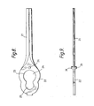
- a cutter blade for pivotal attachment to the eyelet is shown in Figs. 8 and 9.
- the blade consists of an elongate portion 21, the leading edge of which performs the cutting action, and an enlarged head portion 22 with a keyhole opening 23.
- the blade is reversible so that either edge can be used as the leading edge.
- the enlarged portion 24 of the keyhole opening 23 is a snap-fit over the head 17 of the eyelet. Once fitted, the blade can be pulled outwards until the intermediate portion 18 of the eyelet receives the reduced portion 25 of the keyhole opening 23. In this position the blade cannot be detached from the eyelet.
- the blade is retained in this non-detachable position by centrifugal force when the cutter head is subsequently rotated at high speed.
- the blade also includes an opposed pair of "pips" 26, one of which enters a groove 27 (Fig. 1) in the underneath surface of the flange 11 whenever the blade is subjected to a heavy load. Such loads force the blade to pivot about the eyelet until a substantial portion of the blade lies within the periphery of the head 20.
- the pip 26 running in the groove 27 prevents the resulting reversal of centrifugal force on the blade from detaching the blade by preventing movement of the enlarged portion 24 of the keyhole opening 23 back into alignment with the head 17 of the eyelet.
- the eyelet is protected from stones and other obstacles by a step 30 in the flange 11 immediately upstream of the eyelet in the direction of rotation.
- the direction of rotation is anticlockwise as viewed in Fig. 1 and the step 30 is shown most clearly in the scrap section of Fig. 4.
- the step 30 is itself protected by extending it back parallel to the flange 11 for a short length 31 and then providing a lead-in ramp 32.
- the trailing edge of the step 30 is profiled to accommodate the head 22 of the blade should the blade swing forward of its radial position during cutting.
- the opposite side of the cutter head 20 is weighted to counterbalance the eyelet and the blade, and the flange 11 is therefore similarly ramped at 33 as shown in Figs. 1 and 5.
- an alternative cutting element in the form of a short length of nylon line can be connected to the eyelet.
- the line can be passed through the eyelet with a small blob at one end to prevent it running through the eyelet hole 34 when the head is rotated.
- the inside of the hole 34 is radiused to stop the nylon line chafing and, as shown in Figs. 6 and 7, the outer edge of the eyelet is also provided with a part-radius profile to prevent any possibility of the metal edge cutting the line.
- the line might be connected to a keyhole loop which is snapped on to the eyelet in the same manner as the cutter blade.
Landscapes
- Life Sciences & Earth Sciences (AREA)
- Environmental Sciences (AREA)
- Harvester Elements (AREA)
Applications Claiming Priority (4)
| Application Number | Priority Date | Filing Date | Title |
|---|---|---|---|
| GB8320083 | 1983-07-26 | ||
| GB838320083A GB8320083D0 (en) | 1983-07-26 | 1983-07-26 | Cutter heads |
| GB8325663 | 1983-09-26 | ||
| GB838325663A GB8325663D0 (en) | 1983-09-26 | 1983-09-26 | Cutter heads |
Publications (1)
| Publication Number | Publication Date |
|---|---|
| EP0132385A1 true EP0132385A1 (de) | 1985-01-30 |
Family
ID=26286686
Family Applications (1)
| Application Number | Title | Priority Date | Filing Date |
|---|---|---|---|
| EP19840304932 Ceased EP0132385A1 (de) | 1983-07-26 | 1984-07-19 | Schneidsystem mit umlaufenden Schneidelementen |
Country Status (2)
| Country | Link |
|---|---|
| EP (1) | EP0132385A1 (de) |
| GB (1) | GB2143716B (de) |
Cited By (5)
| Publication number | Priority date | Publication date | Assignee | Title |
|---|---|---|---|---|
| WO1998057533A1 (en) * | 1997-06-16 | 1998-12-23 | Peter Thorne | Vegetation cutting tool and blade |
| AU728269B2 (en) * | 1997-06-16 | 2001-01-04 | Peter Thorne | Vegetation cutting tool and blade |
| EP2191709A1 (de) * | 2008-10-28 | 2010-06-02 | Deere & Company | Messerhalter für Drehscheiben-Schneidleiste |
| ITMO20100299A1 (it) * | 2010-10-27 | 2012-04-28 | Tecomec Srl | Elemento tagliente per decespugliatore. |
| US10070582B2 (en) | 2016-04-20 | 2018-09-11 | Tti (Macao Commercial Offshore) Limited | String trimmer head |
Families Citing this family (1)
| Publication number | Priority date | Publication date | Assignee | Title |
|---|---|---|---|---|
| IT212687Z2 (it) * | 1987-11-04 | 1989-07-23 | Calcinai Maria Rosa | Rotore a lame per macchine falciatrici tagliaerba esimilari, realizzato in un pezzo unico formante lame e mozzo di innesto. |
Citations (7)
| Publication number | Priority date | Publication date | Assignee | Title |
|---|---|---|---|---|
| DE1923411A1 (de) * | 1968-05-10 | 1969-11-27 | Texas Industries Inc | Maehmaschine mit schwenkbaren Messern |
| GB1236158A (en) * | 1968-12-18 | 1971-06-23 | Welger Geb | Rotary disc mowers |
| US3690051A (en) * | 1971-12-28 | 1972-09-12 | Black & Decker Mfg Co | Safety lawnmower blade |
| GB1362098A (en) * | 1971-09-28 | 1974-07-30 | Victa Ltd | Pivoted blade assemblies for rotary mowers |
| DE2453181A1 (de) * | 1973-12-12 | 1975-06-19 | Frost & Son C L | Spindelhalterung fuer die spindel eines kreiselmaehers |
| DE2829348A1 (de) * | 1977-07-05 | 1979-01-25 | Irene Kalmar | Grasschneide-zusatzgeraet fuer eine einen drehantrieb aufweisende maschine |
| GB1570252A (en) * | 1977-04-22 | 1980-06-25 | True Temper Corp | Weed cutter construction |
-
1984
- 1984-07-19 EP EP19840304932 patent/EP0132385A1/de not_active Ceased
- 1984-07-19 GB GB8418383A patent/GB2143716B/en not_active Expired
Patent Citations (7)
| Publication number | Priority date | Publication date | Assignee | Title |
|---|---|---|---|---|
| DE1923411A1 (de) * | 1968-05-10 | 1969-11-27 | Texas Industries Inc | Maehmaschine mit schwenkbaren Messern |
| GB1236158A (en) * | 1968-12-18 | 1971-06-23 | Welger Geb | Rotary disc mowers |
| GB1362098A (en) * | 1971-09-28 | 1974-07-30 | Victa Ltd | Pivoted blade assemblies for rotary mowers |
| US3690051A (en) * | 1971-12-28 | 1972-09-12 | Black & Decker Mfg Co | Safety lawnmower blade |
| DE2453181A1 (de) * | 1973-12-12 | 1975-06-19 | Frost & Son C L | Spindelhalterung fuer die spindel eines kreiselmaehers |
| GB1570252A (en) * | 1977-04-22 | 1980-06-25 | True Temper Corp | Weed cutter construction |
| DE2829348A1 (de) * | 1977-07-05 | 1979-01-25 | Irene Kalmar | Grasschneide-zusatzgeraet fuer eine einen drehantrieb aufweisende maschine |
Cited By (8)
| Publication number | Priority date | Publication date | Assignee | Title |
|---|---|---|---|---|
| WO1998057533A1 (en) * | 1997-06-16 | 1998-12-23 | Peter Thorne | Vegetation cutting tool and blade |
| AU728269B2 (en) * | 1997-06-16 | 2001-01-04 | Peter Thorne | Vegetation cutting tool and blade |
| US6357215B1 (en) | 1997-06-16 | 2002-03-19 | Peter Thorne | Vegetation cutting tool and blade |
| EP2191709A1 (de) * | 2008-10-28 | 2010-06-02 | Deere & Company | Messerhalter für Drehscheiben-Schneidleiste |
| ITMO20100299A1 (it) * | 2010-10-27 | 2012-04-28 | Tecomec Srl | Elemento tagliente per decespugliatore. |
| EP2446727A1 (de) * | 2010-10-27 | 2012-05-02 | Tecomec S.r.l. | Schneideelement für eine Heckenschere |
| US8925206B2 (en) | 2010-10-27 | 2015-01-06 | Tecomec S.R.L. | Cutting element for a hedge trimmer |
| US10070582B2 (en) | 2016-04-20 | 2018-09-11 | Tti (Macao Commercial Offshore) Limited | String trimmer head |
Also Published As
| Publication number | Publication date |
|---|---|
| GB8418383D0 (en) | 1984-08-22 |
| GB2143716A (en) | 1985-02-20 |
| GB2143716B (en) | 1986-11-26 |
Similar Documents
| Publication | Publication Date | Title |
|---|---|---|
| US4362007A (en) | Cutting head assembly for a rotary motor | |
| US4825627A (en) | Lawn mower cutting assembly | |
| US6470662B1 (en) | Multiple blade cutting apparatus for rotary lawn mower | |
| US5210998A (en) | Lawn mower with detachable inner members in cutter housing | |
| US4905465A (en) | Rotary cutting member for use with lawn mowers and the like | |
| US5491962A (en) | Cutting head assembly | |
| US4896488A (en) | Trimming attachment for a lawn mower etc. | |
| US5609011A (en) | Rotating mower baffle mechanism | |
| US5884463A (en) | Convertible mower with rotary disc mechanism | |
| US5862598A (en) | Unitary hub for vegetation cutting devices | |
| US5048278A (en) | Rotary cutting member for use with lawn mowers and the like | |
| US4145809A (en) | Rotary mower cutting heads with flexible cutting blades | |
| US3918241A (en) | Cutting unit for rotary lawn mowers | |
| US5363635A (en) | Mulching mower with improved mulching blade | |
| WO1990006673A1 (en) | Grass cutting device | |
| US4819416A (en) | Rotary cutting member for use with lawnmowers and the like | |
| US3964243A (en) | Rotary mower blade with detachable tines | |
| US20020066263A1 (en) | Disc and knife cutter assembly for mowing | |
| US5960619A (en) | Mulching disc for a lawn mower | |
| AU6331680A (en) | Trimming head for vegetation | |
| GB2143716A (en) | Orbital cutting system | |
| US5069025A (en) | Air flow directing device | |
| US4357789A (en) | Safety grass cutter for rotary lawn mower | |
| US5642609A (en) | Multi-cutting edge mulching lawn mower blade | |
| US6311463B1 (en) | Rotary mower cutter disc having self-cleaning knife mount shield |
Legal Events
| Date | Code | Title | Description |
|---|---|---|---|
| PUAI | Public reference made under article 153(3) epc to a published international application that has entered the european phase |
Free format text: ORIGINAL CODE: 0009012 |
|
| AK | Designated contracting states |
Designated state(s): AT BE CH DE FR IT LI LU NL SE |
|
| 17P | Request for examination filed |
Effective date: 19850225 |
|
| 17Q | First examination report despatched |
Effective date: 19860828 |
|
| STAA | Information on the status of an ep patent application or granted ep patent |
Free format text: STATUS: THE APPLICATION HAS BEEN REFUSED |
|
| 18R | Application refused |
Effective date: 19900122 |
|
| RIN1 | Information on inventor provided before grant (corrected) |
Inventor name: RUDD, MICHAEL Inventor name: COOPER, JOHN SAMUEL Inventor name: REYNOLDS, JOHN ALEXANDER Inventor name: FISHER, KEVIN MICHAEL |