EP0132491A1 - Kugelumlauf-Schraubgetriebe - Google Patents
Kugelumlauf-Schraubgetriebe Download PDFInfo
- Publication number
- EP0132491A1 EP0132491A1 EP84101706A EP84101706A EP0132491A1 EP 0132491 A1 EP0132491 A1 EP 0132491A1 EP 84101706 A EP84101706 A EP 84101706A EP 84101706 A EP84101706 A EP 84101706A EP 0132491 A1 EP0132491 A1 EP 0132491A1
- Authority
- EP
- European Patent Office
- Prior art keywords
- nut
- groove
- screw
- band
- ball screw
- Prior art date
- Legal status (The legal status is an assumption and is not a legal conclusion. Google has not performed a legal analysis and makes no representation as to the accuracy of the status listed.)
- Granted
Links
Images


Classifications
-
- F—MECHANICAL ENGINEERING; LIGHTING; HEATING; WEAPONS; BLASTING
- F16—ENGINEERING ELEMENTS AND UNITS; GENERAL MEASURES FOR PRODUCING AND MAINTAINING EFFECTIVE FUNCTIONING OF MACHINES OR INSTALLATIONS; THERMAL INSULATION IN GENERAL
- F16H—GEARING
- F16H25/00—Gearings comprising primarily only cams, cam-followers and screw-and-nut mechanisms
- F16H25/18—Gearings comprising primarily only cams, cam-followers and screw-and-nut mechanisms for conveying or interconverting oscillating or reciprocating motions
- F16H25/20—Screw mechanisms
- F16H25/22—Screw mechanisms with balls, rollers, or similar members between the co-operating parts; Elements essential to the use of such members
- F16H25/2204—Screw mechanisms with balls, rollers, or similar members between the co-operating parts; Elements essential to the use of such members with balls
-
- F—MECHANICAL ENGINEERING; LIGHTING; HEATING; WEAPONS; BLASTING
- F16—ENGINEERING ELEMENTS AND UNITS; GENERAL MEASURES FOR PRODUCING AND MAINTAINING EFFECTIVE FUNCTIONING OF MACHINES OR INSTALLATIONS; THERMAL INSULATION IN GENERAL
- F16H—GEARING
- F16H25/00—Gearings comprising primarily only cams, cam-followers and screw-and-nut mechanisms
- F16H25/18—Gearings comprising primarily only cams, cam-followers and screw-and-nut mechanisms for conveying or interconverting oscillating or reciprocating motions
- F16H25/20—Screw mechanisms
- F16H25/22—Screw mechanisms with balls, rollers, or similar members between the co-operating parts; Elements essential to the use of such members
- F16H25/2204—Screw mechanisms with balls, rollers, or similar members between the co-operating parts; Elements essential to the use of such members with balls
- F16H25/2214—Screw mechanisms with balls, rollers, or similar members between the co-operating parts; Elements essential to the use of such members with balls with elements for guiding the circulating balls
- F16H25/2223—Cross over deflectors between adjacent thread turns, e.g. S-form deflectors connecting neighbouring threads
Definitions
- the invention relates to a screw ball screw mechanism, the spindle and nut of which are each formed with screw cross-sections which are essentially partially circular in cross-section and which delimit at least one ball channel which removes the balls, the nut at least one of the balls from one end section of a screw thread of the ball channel to the other end section of this screw thread has a conductive return duct.
- the balls of a ball recirculation channel are held only by the screw grooves of the spindle and the nut delimiting the ball recirculation channel and forming the ball raceways. If the nut is inadvertently unscrewed too far from the spindle, the balls fall out of the ball circulation channel, with the result that screwing back the nut is associated with considerable difficulties because of the need to reinsert the missing balls beforehand. In addition, for the same reasons, the assembly of such a screw-type ball screw gearbox during manufacture is not very easy.
- the object of the invention is to remedy this and to create a screw screw mechanism in which an unintentional falling out of the balls from the associated screw groove of the nut is prevented when the nut is unscrewed from the spindle and at the same time there is the possibility of a perfect seal between the spindle and to achieve the mother's existing annular gap.
- the above-mentioned screw screw mechanism is inventively characterized in that at least one flexible band is arranged in the nut on the side next to the screw groove delimiting the ball screw channel, and one of the balls of the ball screw channel over at least part of the length of the screw nut of the nut has captive part in the screw groove.
- the band advantageously consists of plastic material and expediently has a lip-shaped holding part formed on a web-like holding part, with which it engages the balls above their centers.
- the lip-shaped holding part which extends over the length of the band and is essentially wedge-shaped in cross section, exerts only a relatively small frictional force on the balls; it partially overlaps the balls and thus securely holds them back in the assigned screw groove.
- the elastic band is advantageously inserted with its holding part into a corresponding groove in the nut, it generally being sufficient for the groove to be delimited with parallel flanks, so that the band with its holding part can simply be pressed in.
- the band is held in a form-fitting manner in the groove formed as a profile groove. Since the band is made of an elastic material, it can usually be simply pushed into the groove in this case too.
- the arrangement is preferably such that the band is arranged between two adjacent screw threads of the nut and is designed with two holding parts holding the balls of the two screw threads.
- the two lip-shaped holding parts can then be formed on a common holding part, which in turn, as already explained, is inserted into a corresponding groove in the nut.
- the band usually extends over the entire circumference of the bore of the nut containing the screw groove. It can be in the area of the return line channel are interrupted, or the arrangement can be such that the return channel is routed over the continuous band here.
- the screw grooves of the nut can be formed by at least one profile ring which is bent in accordance with a screw thread and is essentially channel-shaped in cross section and is arranged in a nut body surrounding it. It is then expedient if the groove or the grooves for receiving the holding part of the band is or are limited by the profile ring or the profile rings.
- a spindle 1 and a nut 2 which are each formed with circumferential screw grooves 3 and 4, which are essentially partially circular in cross section. Between the individual screw threads of the screw groove 3 machined into the circumferential surface of the cylindrical spindle 1 also run helical webs 5, which correspond to webs 6 which correspond to the screw groove (s) 4 arranged in the cylindrical bore 7 of the nut 2.
- the nut 2 contains at least three adjacent closed ball circulation channels, in each of which balls 8 are arranged.
- the balls 8 are passed from one end section of a screw thread of the respective ball circulation channel to the other end section of this screw thread through a return pipe 9, which is formed in the nut 2 or in a return pipe body inserted into a corresponding bore or recess.
- a flexible band 10 or 11 (FIGS. 2, 4) is arranged on the associated helical web 6 of the nut 2, which preferably consists of a plastic material and the balls 8 of the ball circulation channel at least over part the length of the screw groove 4 of the nut captively holds in the recirculating ball channel.
- the flexible band 10 or 11 shown in its cross-section in the details, in particular in FIGS. 4, 6, has at least one lip-shaped one that runs continuously over the length of the band Holding part 12, the cross-sectional shape of which is substantially wedge-shaped.
- the supporting member 12 is integrally connected at a root 13 with a continuous also on the Laena e of the band web-like holding portion 14 having a substantially rectangular cross-sectional shape in the illustrated embodiment.
- a band 10 is arranged in the manner shown in FIGS. 2 and 4, which is formed with two lip-shaped mounting parts 12, each of which is integrally connected via its root 13 to a common mounting part 14.
- the K adjacent to the two outer ugelumlaufbahnen arranged flexible bands 11 are provided in FIG. 6 to er Colorden manner in each case with only one lip-shaped support part 12, but in principle it is also possible to have 10 just go through the flexible strip at this point.
- the flexible band 10 or 9 is held with its holding part 14 in a helical groove 15 arranged centrally in the helical web 6 of the nut 2 between two adjacent screw threads, wherein it rests on the web 6 with at least one shoulder 16 in each case.
- the helical groove 15 is formed here with parallel flanks; in an alternative embodiment, it could also have a different, for example dovetail or part-circular cross-sectional shape, so that the correspondingly designed holding part 14 is held in a form-fitting manner.
- the flexible band 10 or 11 projects with the edge of its lip-shaped holding part 16 over the centers 17 of the balls 8, it extends approximately to the height of the helical webs 5 of the spindle 1 and lies against the balls 8 with a slight elastic force, whereby there is essentially only a linear contact.
- the balls 8 are thus captively held in the screw groove 4 of the nut 2 by the flexible band 10 or 11, so that it can be unscrewed from the spindle 1 without the balls 8 falling out.
- the flexible band 10 can, as already mentioned earlier, be inserted continuously in the manner described in the groove 15 machined into the helical web 6 over the entire axial length of the nut 2. Then the arrangement in the area of the return channels 9, as shown in Fig. 2, must be designed, i.e. each return duct 9 must guide the balls 8 in the nut 2 over the band 10 crossed by them and the associated groove 15 in a radially outer region.
- the arrangement can also be such that the flexible band is interrupted in the area of the respective return duct 9, as indicated at 20 in FIG. 2.
- the single-lipped band 11 can be used on the outside.
- the screw grooves 4 directly into the selected one hardenable material of the mother 2 are incorporated - which requires a considerable amount of production - are in the embodiment according to the Fiy. 5, 6, the helical grooves 4, are limited in cross-section substantially gutter-shaped profile rings 21, which in a surrounding nut body 2a, which can also consist of plastics material, b is the mother of three, each corresponding to a helical curved inge poured or injected.
- Each of the profile rings 21 consists of two symmetrical ring parts 21a, 21b, which are each stamped and bent from a corresponding sheet steel part with high precision. The two ring parts 21a, 21b are exactly fixed in their mutual position by the nut body 2a.
- Each profile ring 21 is provided with a molded-on short section 22 which forms the return duct 9 and which is arranged transversely in accordance with the return duct according to FIG. 2.
- the helical grooves 15 used to hold the holding part 14 of the flexible band 10 or 11 are each delimited by corresponding annular recesses 23 in the profile rings 21.
Landscapes
- Engineering & Computer Science (AREA)
- General Engineering & Computer Science (AREA)
- Mechanical Engineering (AREA)
- Transmission Devices (AREA)
- Moulds For Moulding Plastics Or The Like (AREA)
Abstract
Description
- Die Erfindung betrifft ein Kugelumlauf-Schraubgetriebe, dessen Spindel und Mutter jeweils mit im Querschnitt im wesentlichen teilkreisförmigen Schraubennuten ausgebildet sind, die wenigstens einen die Kugeln enttenden Kugelumlaufkanal begrenzen, wobei die Mutter wenigstens einen die Kugeln von einem Endabschnitt eines Schraubenganges des Kugelumlaufkanales zu dem anderen Endabschnitt dieses Schraubenganges leitenden Rückleitungskanal aufweist.
- Die Kugeln eines Kugelumlaufkanales sind dabei lediglich durch die den Kugelumlaufkanal begrenzenden, die Kugellaufbahnen bildenden Schraubennuten der Spindel und der Mutter gehalten. Wird die Mutter unbeabsichtigt zu weit von der Spindel abgeschraubt, so fallen die Kugeln aus dem Kugelumlaufkanal heraus, mit dem Ergebnis, daß das Zurückschrauben der Mutter wegen der Notwendigkeit, die fehlenden Kugeln vorher wieder einzusetzen, mit erheblichen Schwierigkeiten verbunden ist. Außerdem ist auch aus den gleichen Gründen die Montage eines solchen Kugelumlauf-Schraubgetriebes bei der Herstellung nicht ganz einfach.
- Schließlich können beim Einsatz des Kugelumlauf-Schraubgetriebes in verschmutzter Umgebung Verunreinigungen durch den zwLschen der Mutter und der Spindel vorhandenen Ringspalt in die die Kugeln enthaltenden Scnraubennuten eindringen und zu einer Beschädigung oder Zerstörung des Getriebes führen, während andererseits über diesen Ringspalt auch ein Schmiermittelaustritt erfolgen kann. Es müssen deshalb häufig besondere Abdichtungsmaßnahmen durch Dichtungsmanschetten od.dgl. getroffen werden, die verhältnismäßig teuer und aufwendig sind.
- Aufgabe der Erfindung ist es, hier abzuhelfen und ein Kugelumlauf-Schraubgetriebe zu schaffen, bei dem ein unbeabsichtigtes Herausfallen der Kugeln aus der zugehörigen Schraubennut der Mutter bei von der Spindel abgeschraubter Mutter verhindert ist und gleichzeitig die Möglichkeit besteht, eine einwandfreie Abdichtung des zwischen der Spindel und der Mutter vorhandenen Ringspaltes zu erzielen.
- Zur Lösung dieser Aufgabe ist das eingangs genannte Kugelumlauf-Schraubgetriebe erfindungsgemäß dadurch gekennzeichnet, daß in der Mutter seitlich neben der' den Kugelumlaufkanal begrenzenden Schraubennut wenigstens ein biegsames Band angeordnet ist, das einen die Kugeln des Kugelumlaufkanales zumindest über einen Teil der Länge der Schraubennut der Mutter in deren Schraubennut unverlierbar haltenden Teil aufweist.
- Das Band besteht mit Vorteil aus Kunststoffmaterial und weist zweckmäßigerweise einen an einem stegartigen Halteteil angeformten lippenförmigen Halterungsteil auf, mit dem es an den Kugeln oberhalb deren Mitten angreift. Der lippenförmige Halterungsteil, der sich über die Länge des Bandes erstreckt und im Querschnitt im wesentlichen keilförmig ist, übt nur eine verhältnismäßig kleine Reibungskraft auf die Kugeln aus; er übergreift die Kugeln teilweise und hält sie damit sicher in der zugeordneten Schraubennut zurück.
- Das elastische Band ist mit Vorteil mit seinem Halteteil in eine entsprechende Nut der Mutter eingefügt, wobei es in der Regel genügt, daß die Nut parallelflankig begrenzt ist, so daß das Band mit seinem Halteteil einfach eingedrückt werden kann. Es sind aber auch Ausführungsformen denkbar, bei denen das Band in der als Profilnut ausgebildeten Nut formschlüssig gehaltert ist. Da das Band aus einem elastischen Material besteht, kann es auch in diesem Fall in der Regel einfach in die Nut eingedrückt werden.
- Ist ein solches Band auf der Außenseite des vorne liegenden Kugelumlaufkanales vorgesehen, so dient es gleichzeitig dazu, daß der zwischen der Mutter und der Spindel bestehende Ringspalt nach außen hin auf dieser Seite durch das Band abgedichtet ist.
- Weist das Kugelumlauf-Schraubgetriebe zur Erzielung der notwendigen Tragzahl mehrere Kugelumlaufkanäle auf, so ist die Anordnung mit Vorzug derart getroffen, daß das Band zwischen zwei benachbarten Schraubengängen der Mutter angeordnet und mit zwei die Kugeln der beiden Schraubengänge halternden Halteteilen ausgebildet ist. Dabei können dann die beiden lippenförmigen Halterungsteile an einem gemeinsamen Halteteil angeformt sein, das seinerseits, wie bereits erläutert, in eine entsprechende Nut der Mutter eingefügt ist.
- Das Band erstreckt sich in der Regel über den gesamten Umfang der die Schraubennut enthaltenden Bohrung der Mutter. Es kann im Bereiche des Rückleitungskanales unterbrochen sein, oder aber die Anordnung kann derart getroffen sein, daß der Rückleitungskanal über das hier durchgehende Band hinweggeleitet ist.
- Zur Vereinfachung der Herstellung des Kugelumlauf-Schraubgetriebes können die Schraubennuten der Mutter durch wenigstens einen entsprechend einem Schraubengang gebogenen, im Querschnitt im wesentlichen rinnenförmigen Profilring gebildet sein, der in einem ihn umgebenden Mutterkörper angeordnet ist. Dabei ist es dann zweckmäßig, wenn die Nut bzw. die Nuten zur Aufnahme des Halteteiles des Bandes durch den Profilring oder die Profilringe begrenzt ist bzw. sind.
- In der Zeichnung sind Ausführungsbeispiele des Gegenstandes der Erfindung dargestellt. Es zeigen:
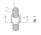
- Fig. 1 ein Kugelumlauf-Schraubgetriebe in perspektivischer Darstellung,
- Fig. 2 die Mutter des Kugelumlauf-Schraubgetriebes nach Fig. 1, teilweise im axialen Schnitt, in einer Seitenansicht, im Ausschnitt und in einem anderen Maßstab,
- Fig. 3 die Mutter nach Fig. 2, geschnitten längs der Linie III-III der Fig. 2 in einer Seitenansicht und im Ausschnitt,
- Fig. 4 das Kugelumlauf-Schraubgetriebe nach Fig. 1, geschnitten längs der Linie IV-IV der Fig. 1,in einer Seitenansicht,im Ausschnitt und in einem anderen Maßstab,
- Fig. 5 ein Kugelumlauf-Schraubgetriebe gemäß der Erfindung in einer abgeänderten Ausführungsform und in einer stirnseitigen Ansicht und
- Fig. 6 das Kugelumlauf-Schraubgetriebe nach Fig. 5, geschnitten längs der Linie VI-VI der Fig. 5, in einer Seitenansicht, im Ausschnitt und in einem anderen Maßstab.
- Das in den Fig. 1 bis 3 dargestellte Kugelumlauf-Schraubgetriebe weist eine Spindel 1 und eine Mutter 2 auf, die jeweils mit umlaufenden, im Querschnitt im wesentlichen teilkreisförmigen Schraubennuten 3 bzw. 4 ausgebildet sind. Zwischen den einzelnen Schraubengängen der in die Umfangsfläche der zylindrischen Spindel 1 eingearbeiteten Schraubennut 3 verlaufen ebenfalls schraubenförmige Stege 5, denen Stege 6 entsprechen, die zwischen den Schraubengängen der in der zylindrischen Bohrung 7 der Mutter 2 angeordneten Schraubennut(en) 4 entsprechen.
- Die Mutter 2 enthält mindestens drei nebeneinanderliegende geschlossene Kugelumlaufkanäle, in denen jeweils Kugeln 8 angeordnet sind. Die Kugeln 8 werden von einem Endabschnitt eines Schraubenganges des jeweiligen Kugelumlaufkanales zu dem anderen Endabschnitt dieses Schraubenganges durch einen Rückleitungskanal 9 geleitet, der in der Mutter 2 oder in einem in eine entsprechende Bohrung oder Ausnehmung derselben eingesetzten Rückleitungskörper ausgebildet ist.
- Seitlich neben der einen Kugelumlaufkanal begrenzenden Schraubennut 4 ist auf dem zugehörigen schraubenförmigen Steg 6 der Mutter 2 ein biegsames Band 10 bzw. 11 (Fig. 2, 4) angeordnet, das vorzugsweise aus einem Kunststoffmaterial besteht und die Kugeln 8 des Kugelumlaufkanales zumindest über einen Teil der Länge der Schraubennut 4 der Mutter unverlierbar in dem Kugelumlaufkanal hält.
- Zu diesem Zwecke weist das in seinem Querschnitt in den Einzelheiten insbesondere in den Fig. 4, 6 dargestellte biegsame Band 10 bzw. 11 wenigstens ein über die Länge des Bandes durchgehendes lippenförmiges Halterungsteil 12 auf, dessen Querschnittsgestalt im wesentlichen keilförmig ist. Das Halterungsteil 12 ist an einer Wurzel 13 mit einem ebenfalls über die Länae des Bandes durchgehenden stegartigen Halteteil 14 einstückig verbunden, das bei der dargestellten Ausführungsform eine im wesentlichen rechteckige Querschnittsgestalt aufweist.
- Zwischen zwei benachbarten Schraubengängen der Mutter 2 ist in der aus den Fig. 2 und 4 ersichtlichen Weise jeweils ein Band 10 angeordnet, das mit zwei lippenförmigen Halterungsteilen 12 ausgebildet ist, die jeweils über ihre Wurzel 13 mit einem gemeinsamen Halteteil 14 einstückig verbunden sind. Die neben den beiden außen liegenden Kugelumlaufbahnen angeordneten biegsamen Bänder 11 sind in der aus Fig. 6 zu ersehenden Weise jeweils lediglich mit einem lippenförmigen Halterungsteil 12 versehen, doch ist es grundsätzlich auch möglich, an dieser Stelle das biegsame Band 10 einfach durchgehen zu lassen.
- Das biegsame Band 10 bzw. 9 ist mit seinem Halteteil 14 in eine in dem schraubenförmigen Steg 6 der Mutter 2 zwischen zwei benachbarten Schraubengängen mittig angeordneten schraubenförmigen Nut 15 gehaltert, wobei es auf dem Steg 6 jeweils mit wenigstens einer Schulter 16 aufliegt. Die schraubenförmige Nut 15 ist hier parallelflankig ausgebildet; in einer alternativen Ausführungsform könnte sie auch eine andere, beispielsweise schwalbenschwanz- oder teilkreisförmige Querschnittsgestalt aufweisen, so daß das entsprechend gestaltete Halteteil 14 formschlüssig gehaltert ist.
- Das biegsame Band 10 bzw. 11 ragt mit der Randkante seines lippenförmigen Halterungsteiles 16 über die Mitten 17 der Kugeln 8, wobei es sich etwa bis zur Höhe der schraubenförmigen Stege 5 der Spindel 1 erstreckt und liegt mit leichter elastischer Kraft an den Kugeln 8 an, wobei sich eine im wesentlichen lediglich linienförmige Berührung ergibt.
- Die Kugeln 8 sind damit durch das biegsame Band 10 bzw. 11 unverlierbar in der Schraubennut 4 der Mutter 2 gehaltert, so daß diese von der Spindel 1 abgeschraubt werden kann, ohne daß die Kugeln 8 herausfallen.
- Das biegsame Band 10 kann, wie bereits früher erwähnt, durchgehend über die gesamte axiale Länge der Mutter 2 in die in den schraubenförmigen Steg 6 eingearbeitete Nut 15 in der beschriebenen Weise eingesetzt sein. Dann muß die Anordnung im Bereiche der Rückleitungskanäle 9, wie in Fig. 2 dargestellt, gestaltet sein, d.h. jeder Rückleitungskanal 9 muß die Kugeln 8 in der Mutter 2 über das von ihm überquerte Band 10 und die zugehörige Nut 15 in einem radial außenliegenden Bereich hinwegleiten.
- Alternativ kann die Anordnung aber auch derart getroffen sein, daß das biegsame Band in dem Bereich des jeweiligen Rückleitungskanales 9 unterbrochen ist, wie dies in Fig. 2 bei 20 angedeutet ist. In diesem Falle kann außen das einlippige Band 11 verwendet werden.
- Während bei dem im Vorstehenden anhand der Fig. 1 bis 4 erläuterten Kugelumlauf-Schraubgetriebe die Schraubennuten 4 unmittelbar in das entsprechend ausgewählte härtbare Material der Mutter 2 eingearbeitet sind - was einen erheblichen Herstellungsaufwand bedingt - sind bei der Ausführungsform nach den Fiy. 5, 6 die Schraubennuten 4 der Mutter durch drei,jeweils entsprechend einem Schraubengang gebogene, im Querschnitt im wesentlichen rinnenförmige Profilringe 21 begrenzt, die in einen sie umgebenden Mutterkörper 2a, der auch aus Kunststoffmaterial bestehen kann, bingegossen oder eingespritzt sind. Jeder der Profilringe 21 besteht aus zwei symmetrischen Ringteilen 21a, 21b, die jeweils aus einem entsprechenden Stahlblechteil mit hoher Präzision geprägt und gebogen sind. Die beiden Ringteile 21a, 21b sind durch den Mutterkörper 2a in ihrer gegenseitigen Lage exakt fixiert.
- Jeder Profilring 21 ist mit einem angeformten, den Rückleitungskanal 9 bildenden kurzen Abschnitt 22 versehen, der entsprechend dem Rückleitungskanal nach Fig. 2 querverlaufend angeordnet ist.
- Bei dieser Ausführungsform sind die zur Aufnahme des Halteteiles 14 des biegsamen Bandes 10 bzw. 11 dienenden schraubenförmigen Nuten 15 jeweils durch entsprechende randseitige, ringförmige Vertiefungen 23 der Profilringe 21 begrenzt.
- Im übrigen ist die Anordnung entsprechend der anhand der Fig. 1 bis 4 beschriebenen Ausführungsform, wobei gleiche Bezugszeichen gleiche Teile beschreiben, so daß sich eine weitere Erörterung insoweit erübrigt.
Claims (10)
Priority Applications (1)
| Application Number | Priority Date | Filing Date | Title |
|---|---|---|---|
| AT84101706T ATE31207T1 (de) | 1983-06-29 | 1984-02-18 | Kugelumlauf-schraubgetriebe. |
Applications Claiming Priority (2)
| Application Number | Priority Date | Filing Date | Title |
|---|---|---|---|
| DE19833323347 DE3323347A1 (de) | 1983-06-29 | 1983-06-29 | Kugelumlauf-schraubgetriebe |
| DE3323347 | 1983-06-29 |
Publications (2)
| Publication Number | Publication Date |
|---|---|
| EP0132491A1 true EP0132491A1 (de) | 1985-02-13 |
| EP0132491B1 EP0132491B1 (de) | 1987-12-02 |
Family
ID=6202635
Family Applications (1)
| Application Number | Title | Priority Date | Filing Date |
|---|---|---|---|
| EP84101706A Expired EP0132491B1 (de) | 1983-06-29 | 1984-02-18 | Kugelumlauf-Schraubgetriebe |
Country Status (5)
| Country | Link |
|---|---|
| EP (1) | EP0132491B1 (de) |
| JP (1) | JPS6014650A (de) |
| AT (1) | ATE31207T1 (de) |
| DE (1) | DE3323347A1 (de) |
| ES (1) | ES531688A0 (de) |
Families Citing this family (10)
| Publication number | Priority date | Publication date | Assignee | Title |
|---|---|---|---|---|
| DE3444134C2 (de) * | 1984-09-12 | 1986-10-09 | Gebr. Bode & Co GmbH, 3500 Kassel | Kugelschraubgetriebe zur Umwandlung einer axialen Bewegung in eine Drehbewegung und umgekehrt für Maschinenbauteile |
| DE3930900A1 (de) * | 1989-09-15 | 1991-03-28 | Steinmeyer August Gmbh Co Kg | Kugelgewindetrieb |
| CN1557024B (zh) | 2001-07-24 | 2010-04-07 | 美商克立股份有限公司 | 绝缘栅铝镓氮化物/氮化钾高电子迁移率晶体管(hemt) |
| TWI221512B (en) | 2002-04-15 | 2004-10-01 | Smc Corp | Ball screw mechanism |
| US7692263B2 (en) | 2006-11-21 | 2010-04-06 | Cree, Inc. | High voltage GaN transistors |
| US8212290B2 (en) | 2007-03-23 | 2012-07-03 | Cree, Inc. | High temperature performance capable gallium nitride transistor |
| JP4941134B2 (ja) * | 2007-07-05 | 2012-05-30 | 日本精工株式会社 | 直動ねじ装置 |
| DE102007046382B4 (de) | 2007-09-27 | 2012-05-10 | Getrag Getriebe- Und Zahnradfabrik Hermann Hagenmeyer Gmbh & Cie Kg | Rotations-Translationswandler, Aktuatoranordnung und Schaltkupplungsanordnung |
| JP5120488B2 (ja) * | 2011-11-25 | 2013-01-16 | 日本精工株式会社 | 直動ねじ装置 |
| TWI509171B (zh) * | 2014-06-16 | 2015-11-21 | Hiwin Tech Corp | Tunnel ball screw |
Citations (1)
| Publication number | Priority date | Publication date | Assignee | Title |
|---|---|---|---|---|
| DE8236312U1 (de) * | 1982-12-24 | 1983-04-14 | Skf Kugellagerfabriken Gmbh, 8720 Schweinfurt | Kugelmutter |
-
1983
- 1983-06-29 DE DE19833323347 patent/DE3323347A1/de not_active Withdrawn
-
1984
- 1984-02-18 AT AT84101706T patent/ATE31207T1/de not_active IP Right Cessation
- 1984-02-18 EP EP84101706A patent/EP0132491B1/de not_active Expired
- 1984-04-17 ES ES531688A patent/ES531688A0/es active Granted
- 1984-05-16 JP JP59096725A patent/JPS6014650A/ja active Pending
Patent Citations (1)
| Publication number | Priority date | Publication date | Assignee | Title |
|---|---|---|---|---|
| DE8236312U1 (de) * | 1982-12-24 | 1983-04-14 | Skf Kugellagerfabriken Gmbh, 8720 Schweinfurt | Kugelmutter |
Also Published As
| Publication number | Publication date |
|---|---|
| DE3323347A1 (de) | 1985-01-10 |
| ES8502232A1 (es) | 1984-12-16 |
| JPS6014650A (ja) | 1985-01-25 |
| EP0132491B1 (de) | 1987-12-02 |
| ATE31207T1 (de) | 1987-12-15 |
| ES531688A0 (es) | 1984-12-16 |
Similar Documents
| Publication | Publication Date | Title |
|---|---|---|
| DE3307010C2 (de) | ||
| DE2945594C2 (de) | Linearlager mit vier Kugelumläufen | |
| DE2941565C2 (de) | Kugelgewindetrieb | |
| DE2355844B2 (de) | Kugelgewindespindel | |
| DE3739059A1 (de) | Vorrichtung zur umwandlung einer drehbewegung in eine axialbewegung | |
| DE3504061A1 (de) | Linearlagersystem und verfahren zur herstellung solcher systeme | |
| WO2017020899A1 (de) | Kugelgewindetrieb | |
| DE69313579T2 (de) | Führungseinheit für gradlinige Wälzbewegungen | |
| EP0132491A1 (de) | Kugelumlauf-Schraubgetriebe | |
| DE19815525A1 (de) | Linearführung mit zwangsgeführtem Käfig | |
| DE19815526B4 (de) | Linearführung mit Zwangsführung des Käfigs | |
| DE3347869C2 (de) | ||
| DE3805392C2 (de) | ||
| EP0008129A1 (de) | Lagergehäuse | |
| EP0208839A2 (de) | Lagerbuchse | |
| EP0168663A2 (de) | Kunststoffgleitlager | |
| EP0132492A1 (de) | Kugelumlauf-Schraubgetriebe | |
| DE102006033852A1 (de) | Schmiereinheit | |
| DE2352453A1 (de) | Kugel-schraubengetriebe | |
| DD293404A5 (de) | Linearkugelbuechse | |
| DE102020202872A1 (de) | Linearführungseinrichtung | |
| DE3930900A1 (de) | Kugelgewindetrieb | |
| DE4428558A1 (de) | Führungsschiene für rollende Lastenträger | |
| DE29601245U1 (de) | Wälzlager | |
| DE19614513B4 (de) | Linearwälzlager mit einer U-förmigen Führungsschiene |
Legal Events
| Date | Code | Title | Description |
|---|---|---|---|
| PUAI | Public reference made under article 153(3) epc to a published international application that has entered the european phase |
Free format text: ORIGINAL CODE: 0009012 |
|
| AK | Designated contracting states |
Designated state(s): AT BE CH FR GB IT LI LU NL SE |
|
| 17P | Request for examination filed |
Effective date: 19850729 |
|
| 17Q | First examination report despatched |
Effective date: 19860911 |
|
| GRAA | (expected) grant |
Free format text: ORIGINAL CODE: 0009210 |
|
| AK | Designated contracting states |
Kind code of ref document: B1 Designated state(s): AT BE CH FR GB IT LI LU NL SE |
|
| REF | Corresponds to: |
Ref document number: 31207 Country of ref document: AT Date of ref document: 19871215 Kind code of ref document: T |
|
| ITF | It: translation for a ep patent filed | ||
| ET | Fr: translation filed | ||
| PLBE | No opposition filed within time limit |
Free format text: ORIGINAL CODE: 0009261 |
|
| STAA | Information on the status of an ep patent application or granted ep patent |
Free format text: STATUS: NO OPPOSITION FILED WITHIN TIME LIMIT |
|
| 26N | No opposition filed | ||
| PGFP | Annual fee paid to national office [announced via postgrant information from national office to epo] |
Ref country code: GB Payment date: 19901211 Year of fee payment: 8 |
|
| PGFP | Annual fee paid to national office [announced via postgrant information from national office to epo] |
Ref country code: AT Payment date: 19910128 Year of fee payment: 8 |
|
| PGFP | Annual fee paid to national office [announced via postgrant information from national office to epo] |
Ref country code: LU Payment date: 19910131 Year of fee payment: 8 |
|
| PGFP | Annual fee paid to national office [announced via postgrant information from national office to epo] |
Ref country code: SE Payment date: 19910218 Year of fee payment: 8 |
|
| PGFP | Annual fee paid to national office [announced via postgrant information from national office to epo] |
Ref country code: FR Payment date: 19910222 Year of fee payment: 8 |
|
| PGFP | Annual fee paid to national office [announced via postgrant information from national office to epo] |
Ref country code: BE Payment date: 19910227 Year of fee payment: 8 |
|
| ITTA | It: last paid annual fee | ||
| PGFP | Annual fee paid to national office [announced via postgrant information from national office to epo] |
Ref country code: NL Payment date: 19910228 Year of fee payment: 8 Ref country code: CH Payment date: 19910228 Year of fee payment: 8 |
|
| EPTA | Lu: last paid annual fee | ||
| PG25 | Lapsed in a contracting state [announced via postgrant information from national office to epo] |
Ref country code: LU Free format text: LAPSE BECAUSE OF NON-PAYMENT OF DUE FEES Effective date: 19920218 Ref country code: GB Effective date: 19920218 Ref country code: AT Effective date: 19920218 |
|
| PG25 | Lapsed in a contracting state [announced via postgrant information from national office to epo] |
Ref country code: SE Effective date: 19920219 |
|
| PG25 | Lapsed in a contracting state [announced via postgrant information from national office to epo] |
Ref country code: BE Effective date: 19920228 |
|
| PG25 | Lapsed in a contracting state [announced via postgrant information from national office to epo] |
Ref country code: LI Effective date: 19920229 Ref country code: CH Effective date: 19920229 |
|
| BERE | Be: lapsed |
Owner name: NEFF GEWINDESPINDELN G.M.B.H. Effective date: 19920228 |
|
| PG25 | Lapsed in a contracting state [announced via postgrant information from national office to epo] |
Ref country code: NL Effective date: 19920901 |
|
| GBPC | Gb: european patent ceased through non-payment of renewal fee | ||
| NLV4 | Nl: lapsed or anulled due to non-payment of the annual fee | ||
| PG25 | Lapsed in a contracting state [announced via postgrant information from national office to epo] |
Ref country code: FR Effective date: 19921030 |
|
| REG | Reference to a national code |
Ref country code: CH Ref legal event code: PL |
|
| REG | Reference to a national code |
Ref country code: FR Ref legal event code: ST |
|
| EUG | Se: european patent has lapsed |
Ref document number: 84101706.4 Effective date: 19920904 |