EP0132500B1 - Système de fixation mécanique - Google Patents
Système de fixation mécanique Download PDFInfo
- Publication number
- EP0132500B1 EP0132500B1 EP84103139A EP84103139A EP0132500B1 EP 0132500 B1 EP0132500 B1 EP 0132500B1 EP 84103139 A EP84103139 A EP 84103139A EP 84103139 A EP84103139 A EP 84103139A EP 0132500 B1 EP0132500 B1 EP 0132500B1
- Authority
- EP
- European Patent Office
- Prior art keywords
- channel
- insert member
- attachment device
- insert
- channel member
- Prior art date
- Legal status (The legal status is an assumption and is not a legal conclusion. Google has not performed a legal analysis and makes no representation as to the accuracy of the status listed.)
- Expired
Links
- 239000000463 material Substances 0.000 claims description 10
- 230000005489 elastic deformation Effects 0.000 claims description 4
- 238000004519 manufacturing process Methods 0.000 claims description 4
- 239000012858 resilient material Substances 0.000 claims description 3
- 239000012528 membrane Substances 0.000 description 18
- 238000003780 insertion Methods 0.000 description 9
- 230000037431 insertion Effects 0.000 description 9
- 239000004744 fabric Substances 0.000 description 7
- 229920002943 EPDM rubber Polymers 0.000 description 5
- 229920001971 elastomer Polymers 0.000 description 4
- 230000014759 maintenance of location Effects 0.000 description 4
- 239000005060 rubber Substances 0.000 description 4
- 238000010276 construction Methods 0.000 description 3
- 239000002184 metal Substances 0.000 description 3
- 239000004033 plastic Substances 0.000 description 3
- 239000000758 substrate Substances 0.000 description 3
- 230000006835 compression Effects 0.000 description 2
- 238000007906 compression Methods 0.000 description 2
- 238000013461 design Methods 0.000 description 2
- 238000000034 method Methods 0.000 description 2
- 239000002985 plastic film Substances 0.000 description 2
- 230000000717 retained effect Effects 0.000 description 2
- 238000013459 approach Methods 0.000 description 1
- 239000010426 asphalt Substances 0.000 description 1
- 230000000295 complement effect Effects 0.000 description 1
- 230000009977 dual effect Effects 0.000 description 1
- HYBBIBNJHNGZAN-UHFFFAOYSA-N furfural Chemical compound O=CC1=CC=CO1 HYBBIBNJHNGZAN-UHFFFAOYSA-N 0.000 description 1
- 238000009434 installation Methods 0.000 description 1
- 238000012986 modification Methods 0.000 description 1
- 230000004048 modification Effects 0.000 description 1
- 230000002093 peripheral effect Effects 0.000 description 1
- 229920006255 plastic film Polymers 0.000 description 1
- 238000003825 pressing Methods 0.000 description 1
- 238000007789 sealing Methods 0.000 description 1
- 239000004575 stone Substances 0.000 description 1
- 239000000126 substance Substances 0.000 description 1
- 238000006467 substitution reaction Methods 0.000 description 1
- 229920002725 thermoplastic elastomer Polymers 0.000 description 1
- XLYOFNOQVPJJNP-UHFFFAOYSA-N water Substances O XLYOFNOQVPJJNP-UHFFFAOYSA-N 0.000 description 1
Images


Classifications
-
- E—FIXED CONSTRUCTIONS
- E04—BUILDING
- E04D—ROOF COVERINGS; SKY-LIGHTS; GUTTERS; ROOF-WORKING TOOLS
- E04D5/00—Roof covering by making use of flexible material, e.g. supplied in roll form
- E04D5/14—Fastening means therefor
- E04D5/141—Fastening means therefor characterised by the location of the fastening means
- E04D5/143—Fastening means therefor characterised by the location of the fastening means in the field of the flexible material
-
- E—FIXED CONSTRUCTIONS
- E04—BUILDING
- E04D—ROOF COVERINGS; SKY-LIGHTS; GUTTERS; ROOF-WORKING TOOLS
- E04D5/00—Roof covering by making use of flexible material, e.g. supplied in roll form
- E04D5/14—Fastening means therefor
- E04D5/144—Mechanical fastening means
- E04D5/146—Linear fastening means, e.g. strips
-
- E—FIXED CONSTRUCTIONS
- E04—BUILDING
- E04D—ROOF COVERINGS; SKY-LIGHTS; GUTTERS; ROOF-WORKING TOOLS
- E04D5/00—Roof covering by making use of flexible material, e.g. supplied in roll form
- E04D5/14—Fastening means therefor
- E04D5/144—Mechanical fastening means
- E04D5/147—Mechanical fastening means not perforating the flexible material
-
- F—MECHANICAL ENGINEERING; LIGHTING; HEATING; WEAPONS; BLASTING
- F16—ENGINEERING ELEMENTS AND UNITS; GENERAL MEASURES FOR PRODUCING AND MAINTAINING EFFECTIVE FUNCTIONING OF MACHINES OR INSTALLATIONS; THERMAL INSULATION IN GENERAL
- F16B—DEVICES FOR FASTENING OR SECURING CONSTRUCTIONAL ELEMENTS OR MACHINE PARTS TOGETHER, e.g. NAILS, BOLTS, CIRCLIPS, CLAMPS, CLIPS OR WEDGES; JOINTS OR JOINTING
- F16B5/00—Joining sheets or plates, e.g. panels, to one another or to strips or bars parallel to them
- F16B5/06—Joining sheets or plates, e.g. panels, to one another or to strips or bars parallel to them by means of clamps or clips
- F16B5/0692—Joining sheets or plates, e.g. panels, to one another or to strips or bars parallel to them by means of clamps or clips joining flexible sheets to other sheets or plates or to strips or bars
Definitions
- the invention relates to an attachment device according to the preamble of claim 1.
- Such a device is known from MARTINEZ, U.S. Patent US-A-3,757,479. It discloses a mirror frame having an external channel surrounding the mirror into which a flexible strip formed from a flexible resilient synthetic plastic or rubber is to be inserted in order to attach mirror sheet to the frame.
- the flexible strip is a continuous strip which fits about the frame; it is initially bent into a rectangular shape, and is illustrated in its normal, V-shaped condition.
- a channel groove is mitered and has an arcuate inner surface which is complementary to one arcuate outer end of the flexible strip, which is rounded and which has substantially the same radius as each undercut portion of groove. Wings are pressed so as to approach one another, and then inserted into the mitered portions of channel.
- the strip undergoes a snap or toggle action, and can neither come loose nor come out of the groove.
- the toggle action depends upon the normal width of the strip, when it is not compressed being greater than the normal width of the strip when it is in the groove. This is because the strip is flatter when in the groove than in its normal, unflexed inverted V-shape. The strip is therefore in compression when it is in the groove because it is flatter in the groove than when in its normal unconstricted condition.
- the inclined surfaces prevent the strip from narrowing, and prevent it from increasing its angularity when in the groove.
- the retaining strip is in compression, when it is serving to retain the mirror sheet against the entire inner surface of slot 25.
- insert member 14a of the present invention would not be capable of retaining more than one sheet within a channel, as insert member 14a of the present invention is capable of doing. Nor would it be able to do so when in a relaxed state, as defined by the present claims.
- MARTINEZ essentially requires that the undercut channel portions and ends of strip, be complementarily configured in order to securely retain the mirror sheet within the channel.
- Adhered roof membrane retention systems suffer from a cost penalty while mechanical fastening systems generally require fixation to the roofing substrate by metal fasteners with metal or rubberized nailing strips.
- Netherlands Patent NL-A-7,906,086 (corresponding to DE-U-7823881) to Agro discloses a fixture arrangement for foilsheets for the erection of roof coverings and the like which comprises a rail with an approximately C-shaped profile.
- This rail has a smooth back and top and bottom grooves for a clamp frame which is flat on one side.
- the width of the frame is greater than the distance between the edges of the frame guide grooves in the rail and smaller or equal to the distance between the edge of the lower guide groove and the top of the uppermost guide. groove.
- French Patent FR-A-2,263,407 to Hirota appears to disclose an apparatus for maintaining a soft sheeting member C on a structural greenhouse framework.
- This apparatus incorporates a substantially zig-zag spring which is positioned within a diverging channel of a retainer. The spring securely retains the flexible membrane C within this channel.
- Austrian Patent AU-A-216,192 to Fural appears to disclose a structure having a flexible membrane positioned thereon wherein the membrane extends over a reverse-tapered ridge and is maintained thereon by a fastening element which incorporates pivotally hinged members and a locking element wherein these members fit over the ridge and the flexible membrane.
- U.S. Patent US-A-4,170,810 to Peleg discloses an apparatus for securing a flexible sheet to building structures wherein, as best shown in Fig. 1, a substantially U-shaped channel member is used to receive the flexible membrane. Two engaging-members are inserted into the channel member, over the flexible member, to tightly clamp the sheet against the channel member.
- U.S. Patent US-A-4,189,880 to Ballin discloses an apparatus for attaching a plastic film along the peripheral edge of the support frame by a spline.
- a plastic sheet is attached to a window by placing it within the channel member and after such placement a spline, preferably formed of a semi-rigid plastic material, is inserted into the channel. After insertion it forces the adjacent walls outwardly into a deformed position but once fully inserted the member is securely held between the channel and the spline member.
- French Patent FR-A-1,467,374 to Buordelot appears to disclose a flexible strip with a groove thereon that apparently functions to facilitate entry into a rigid C-shaped channel to fixedly retain the strip therein.
- U.S. Patent US-A-4,234,035 to Babbs in Figs. 1 and 2 discloses a device for holding trim to upholstered furniture wherein a semi-rigid U-shaped member is attached to the chair and a contoured flexible strip is wedged thereinto.
- the strip utilizes a pair of ribs 13 that are spaced apart in order to give the strip a gap or track.
- U.S. Patent US-A-3,681,887d to Loew discloses a decorative trim strip for an automobile.
- Both the channel and the locking strip are composed of a flexible material.
- U.S. Patent US-A-3,581,848 to Wiele discloses a device for attaching a flexible sheet to a rigid structure which can be used, for example, in awnings.
- the device incorporates a flexible locking strip having a groove thereon which enables a locking strip to hinge or bend inwardly.
- German Patent Publication DE-A-2,433,669 pertains to a device for securing loosely placed roofing membranes wherein a cone-shaped base member is first attached to the roof and the membrane is secured between the base member and a top cap member yieldingly fitting into a restricted bore in the base member. A retaining member is then inserted into a central aperture of the cap member to secure the cap member to the base member.
- the attachment device of the present invention mechanically secures a flexible sheet or membrane to a channel member, having a central longitudinal slot, via a flexible, resilient insert member wherein the channel member is of a generally rectangular form in transverse cross-section.
- the insert member utilized for retaining the flexible sheet is made of a flexible resilient material and has a central longitudinal flex notch in its top surface wherein the flex notch serves to define two adjacent wing portions that permit the temporary elastic deformation of the insert member into an inverted V-shape so as to allow insertion of the insert member, together with the flexible sheet, into the channel member.
- the insert member may be of a generally rectangular form in a transverse cross-section but is preferably curved, concave in shape, in a transverse cross-section.
- the insert member flexible hinge notch also acts as a hinge member after being inserted into the channel member so that, upon the application of tensile forces to the flexible sheet, the insert member tends to assume its free-state shape which in turn enhances its retention capabilities within the channel member.
- the flexible insert member is defined as having three distinct positions: a first unflexed position; a second flexed position; and a third substantially unflexed position.
- the strip is in a substantially flat position in the channel. It serves to retain at least one rubber sheet within the channel simply by the frictional forces between the insert member and the rubber sheet, which is pressed against one inner surface of channel.
- the method for mechanically securing the flexible sheet within the channel member, via the flexible resilient insert member includes the steps of temporarily elastically deforming the insert member into an inverted V-shape; placing the deformed insert member, together with the flexible sheet, through the channel member slot; and flattening the deformed insert member, thereby causing it to substantially return to its original shape so as to frictionally and yet non- bindingly retain the sheet within the channel member.
- Attachment device 10 which basically includes channel member 12 and insert member 14, is utilized for securing a portion of a flexible sheet 16, interposed therebetween, in a manner to be described hereinafter.
- Channel member 12 as best seen in Figs. 1 and 3 and usually of a rigid, preferably metal construction, is of generally rectangular form in transverse cross section (see Fig. 3) having a substantially flat bottom wall 20 which in turn is provided with a plurality (one shown) of longitudinally spaced outwardly directed protrusions or recesses 22 that are provided with a central aperture 24, the latter permitting the partial passage therethrough of a fastener, such as 26, shown in Figs. 5-7.
- a fastener such as 26, shown in Figs. 5-7.
- channel bottom wall 20 merges into opposed, similarly projecting sidewalls 30a, 30b, which in turn merge into inwardly converging spaced top wall 32, parallel to bottom wall 20, whose opposite inner but spaced smooth edges 34a, 34b serve to define a constricted central longitudinal slot or opening 38.
- the cross sectional area 40 within channel member 12 can be defined as having a predetermined width C (between opposed walls 30a, 30b) a predetermined height B (between bottom and top walls 20, 32 respectively), with the opening in top wall 20 (slot 38) being of a predetermined width A.
- sheet 16 In order to permit the insertion of sheet 16 into the interior of channel member 12, sheet 16 must be at least flexible and is preferably elastic.
- Sheet or membrane 16 may, for example as shown in Fig. 4, be EPDM (Ethylene Propylene Diene Monomer) roofing sheeting having a predetermined thickness t.
- Insert member 14 is preferably constructed of a flexible resilient material such as for example Sentoprene° 103-40, a thermoplastic rubber distributed by the Monsanto Company, Rubber Chemical Division, in Akron, Ohio. Other plastic, elastomeric or rubber-type materials can also be utilized.
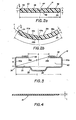
- Insert member 14 which is either flat, i.e., of generally rectangular form in transverse cross-section (Fig. 2a) or preferably of generally curved form (Fig. 2b) in a transverse cross section, has a central longitudinal flexible hinge notch 44 on its top surface 46 that serves to define two adjacent substantially similar wing portions 50, 52.
- the depth of flex notch 44 is approximately one-half of the predetermined thickness h of insert member 14, with the ends 54, the latter being smoothly radiused into top and bottom surfaces 46, 48 respectively.
- the preferred radius of ends 14 is about one-half h.
- insert member 14 has a predetermined extent I.
- Fig. 2a discloses insert member 14 that is generally flat in transverse cross-section
- Fig. 2b shows a preferred insert member 14a that is generally concavely curved in a transverse cross-section.
- top and bottom surfaces 46a, 48a respectively are concave as are adjacent wing portions 50a, 52a and, the transverse extent I of course represents the arc length of member 14a.
- insert member 14a has a predetermined radius of curvature.
- Flex notch 44 not only serves to define the two- adjacent wing portions 50, 52 but also permits the temporary elastic deformation of insert member 14 into an inverted V-shape for insertion of member 14, together with flexible sheet 16, into channel member 12 in the manner to be described with reference to Figs. 5, 6 and 7.
- the preferred ratio of the radius of curvature to arc length of insert member 14a is about 0.9. Furthermore, the preferred ratio of the thickness to the transverse extent of insert members 14, 14a is about 0.09. As noted, the preferred ratio of the depth of the flex notch 44 to thickness t of members 14, 14a is about 0.5. In addition, the preferred ratio of the slot width (A) to the channel width (C) of channel member 12 is about 0.42. Further yet, the preferred ratio of the channel height (B) to the channel width (C) of channel member 12 is about 0.2; and the preferred ratio of the channel height (B) to the slot width (A) of channel member 12 is about 0.46. It should also be understood that dimension D, extending diagonally from the intersection 36 of sidewall 30a and bottom Wall 20 to the smooth remote edge 34b of top wall 32, is less than the transverse or lateral extent (I) of insert members 14, 14a.
- channel member dimensions A, 8 and C are such that it will allow the insertion of not only a single sheet of flexible sheet 16 (which requires channel member 12 to accommodate a top and bottom layer of sheet 16 relative to wing portions 50a, 52a, as best seen in Fig. 7) but even of dual sheets which will of necessity provide two top and bottom layers of sheet 16 relative to the noted wing portions. Such a doubling can occur in the case of a lap splice between separate sheets 16, if such a splice falls within channel area 40, be it parallel with the longitudinal extent of channel member 12 or perpendicular thereto.
- FIG. 5 it depicts channel member 12 attached to any desired type of substrate 28 (best shown in Fig. 7), such as a roofing structure, via a plurality of fasteners 26.
- substrate 28 such as a roofing structure
- curved insert member 14a is temporarily elastically de- fomed into an inverted V-shape by pressing wing portions 50a, 52a together wherein the bottom surface 48a defines the inner surface of the inverted V.
- Insert member 14a in its inverted V-shape, together with sheet 16 is then pushed or placed vertically into channel member 12 through central longitudinal opening 38 until sheet 16 touches channel member bottom wall 20 as shown in Fig. 6, Thereafter pressure is applied downwardly against the now-deformed flex notch 44a (forming the apex of the inverted V) to flatten or return the insert member 14a from its inverted V-shape to approximately its natural shape - either substantially flat with reference to insert member 14 or to the concave shape of curved insert member 14a as shown in Fig. 7.
- the latter may also take the form of being slightly flattened in the center (see Fig. 7) wherein each one of wing portions 50a, 52a however substantially retains its previous radius of curvature.
- insert member 14a consists of the fact that when a tensile force acts at one of fabric ends 16a, 16b, either parallel to or perpendicular to top wall 32, this tensile force is transmitted, by insert member 14a, acting as a beam, to the opposite end 54 of insert member 14a to thereby press its associated portion of fabric 16 against the inner surface of channel member wall portion 30a, 30b.
- the frictional forces present between these parts when in contact with each other, prevents fabric 16 from sliding out of channel member 12 after insert member 14a is inserted.
- insert member flexible hinge notch 44, 44a not only aids in the temporary elastic deformation of insert member 14, 14a but also acts as a hinge member, after insertion into channel member 12, upon the application of the previously-noted tensile forces, thereby causing members 14,14a to assume even more pronounced generally flat (member 14) or greater concave (member 14a) shapes, which in turn will enhance their retention capabilities within channel member 12.
Landscapes
- Engineering & Computer Science (AREA)
- Mechanical Engineering (AREA)
- Architecture (AREA)
- Civil Engineering (AREA)
- Structural Engineering (AREA)
- General Engineering & Computer Science (AREA)
- Tents Or Canopies (AREA)
- Connection Of Plates (AREA)
- Roof Covering Using Slabs Or Stiff Sheets (AREA)
- Laminated Bodies (AREA)
Claims (17)


Applications Claiming Priority (2)
| Application Number | Priority Date | Filing Date | Title |
|---|---|---|---|
| US51662283A | 1983-07-25 | 1983-07-25 | |
| US516622 | 1983-07-25 |
Publications (3)
| Publication Number | Publication Date |
|---|---|
| EP0132500A2 EP0132500A2 (fr) | 1985-02-13 |
| EP0132500A3 EP0132500A3 (en) | 1985-10-16 |
| EP0132500B1 true EP0132500B1 (fr) | 1987-06-03 |
Family
ID=24056399
Family Applications (1)
| Application Number | Title | Priority Date | Filing Date |
|---|---|---|---|
| EP84103139A Expired EP0132500B1 (fr) | 1983-07-25 | 1984-03-22 | Système de fixation mécanique |
Country Status (4)
| Country | Link |
|---|---|
| EP (1) | EP0132500B1 (fr) |
| JP (1) | JPS6026806A (fr) |
| CA (1) | CA1228966A (fr) |
| DE (1) | DE3464080D1 (fr) |
Families Citing this family (2)
| Publication number | Priority date | Publication date | Assignee | Title |
|---|---|---|---|---|
| GB8900328D0 (en) * | 1989-01-07 | 1989-03-08 | Grimalder Ltd | Fixing sheet material |
| FR2720793A1 (fr) * | 1994-06-07 | 1995-12-08 | Jean Fantini | Dispositif pour fixer, accrocher, réunir entre eux des films ou matériaux souples de différentes natures. |
Citations (1)
| Publication number | Priority date | Publication date | Assignee | Title |
|---|---|---|---|---|
| DE7823881U1 (de) * | 1978-08-10 | 1978-12-14 | Agro Import Und Export Handelsgesellschaft Mbh, 8260 Muehldorf | Befestigungsvorrichtung fuer planen oder folien |
Family Cites Families (4)
| Publication number | Priority date | Publication date | Assignee | Title |
|---|---|---|---|---|
| FR1467374A (fr) * | 1966-02-04 | 1967-01-27 | Toitures et clôtures mobiles | |
| US3757479A (en) * | 1971-12-27 | 1973-09-11 | Kamar Products Inc | Mirror |
| US3893212A (en) * | 1973-07-16 | 1975-07-08 | Walter J Curry | Device for making lap joints for plastic film and the like |
| DE2529575A1 (de) * | 1975-07-02 | 1977-01-20 | Gunnar Serneblad | Rampe fuer unterstuetzung und befestigung eines dachbelags |
-
1984
- 1984-03-19 CA CA000449909A patent/CA1228966A/fr not_active Expired
- 1984-03-22 DE DE8484103139T patent/DE3464080D1/de not_active Expired
- 1984-03-22 EP EP84103139A patent/EP0132500B1/fr not_active Expired
- 1984-05-23 JP JP10274884A patent/JPS6026806A/ja active Pending
Patent Citations (1)
| Publication number | Priority date | Publication date | Assignee | Title |
|---|---|---|---|---|
| DE7823881U1 (de) * | 1978-08-10 | 1978-12-14 | Agro Import Und Export Handelsgesellschaft Mbh, 8260 Muehldorf | Befestigungsvorrichtung fuer planen oder folien |
Also Published As
| Publication number | Publication date |
|---|---|
| EP0132500A2 (fr) | 1985-02-13 |
| CA1228966A (fr) | 1987-11-10 |
| EP0132500A3 (en) | 1985-10-16 |
| DE3464080D1 (en) | 1987-07-09 |
| JPS6026806A (ja) | 1985-02-09 |
Similar Documents
| Publication | Publication Date | Title |
|---|---|---|
| US4638532A (en) | Mechanical fastening system | |
| EP0132495B1 (fr) | Attache pour fixer des feuilles flexibles | |
| US4532744A (en) | Locking device for membrane fastener apparatus | |
| CA1239008A (fr) | Raccord de profiles | |
| US4736563A (en) | Greenhouse clip | |
| EP0899466B1 (fr) | Agrafe de fixation pour bandes décoratives | |
| CA1051485A (fr) | Moulure decorative | |
| EP1239096A2 (fr) | Poutres de toiture | |
| US4759157A (en) | Roof edge construction | |
| EP1257718B1 (fr) | Poutres de toiture | |
| EP0610102A1 (fr) | Profilé de toit | |
| US4376359A (en) | Fastener clip for glazed doors | |
| US4001994A (en) | Glazing device | |
| US4531339A (en) | Channel end cap | |
| AU2016216668B2 (en) | Sealing device | |
| EP0132500B1 (fr) | Système de fixation mécanique | |
| GB2245618A (en) | Building covering | |
| WO1982004457A1 (fr) | Couverture de toit ou de paroi et organe de montage pour un crochet de gouttiere | |
| EP3243976B1 (fr) | Connecteur d'épissure de panneau pour des panneaux de plafond linéaires | |
| US3724154A (en) | Fixing devices for roofing and siding sheets | |
| US20010013206A1 (en) | Skylight curb seal and method | |
| JP2730971B2 (ja) | 屋根の目地構造 | |
| JPH0586694A (ja) | 外囲体 | |
| CA2014102C (fr) | Joint d'etancheite pour gouttiere | |
| AU2010100070B4 (en) | An improved skylight panel |
Legal Events
| Date | Code | Title | Description |
|---|---|---|---|
| PUAI | Public reference made under article 153(3) epc to a published international application that has entered the european phase |
Free format text: ORIGINAL CODE: 0009012 |
|
| AK | Designated contracting states |
Designated state(s): BE CH DE FR GB IT LI NL SE |
|
| PUAL | Search report despatched |
Free format text: ORIGINAL CODE: 0009013 |
|
| AK | Designated contracting states |
Designated state(s): BE CH DE FR GB IT LI NL SE |
|
| 17P | Request for examination filed |
Effective date: 19851021 |
|
| 17Q | First examination report despatched |
Effective date: 19860507 |
|
| GRAA | (expected) grant |
Free format text: ORIGINAL CODE: 0009210 |
|
| AK | Designated contracting states |
Kind code of ref document: B1 Designated state(s): BE CH DE FR GB IT LI NL SE |
|
| REF | Corresponds to: |
Ref document number: 3464080 Country of ref document: DE Date of ref document: 19870709 |
|
| ITF | It: translation for a ep patent filed | ||
| ET | Fr: translation filed | ||
| PG25 | Lapsed in a contracting state [announced via postgrant information from national office to epo] |
Ref country code: LI Effective date: 19880331 Ref country code: CH Effective date: 19880331 |
|
| PLBE | No opposition filed within time limit |
Free format text: ORIGINAL CODE: 0009261 |
|
| STAA | Information on the status of an ep patent application or granted ep patent |
Free format text: STATUS: NO OPPOSITION FILED WITHIN TIME LIMIT |
|
| 26N | No opposition filed | ||
| BERE | Be: lapsed |
Owner name: THE FIRESTONE TIRE & RUBBER CY Effective date: 19880331 |
|
| PG25 | Lapsed in a contracting state [announced via postgrant information from national office to epo] |
Ref country code: NL Effective date: 19881001 |
|
| NLV4 | Nl: lapsed or anulled due to non-payment of the annual fee | ||
| PG25 | Lapsed in a contracting state [announced via postgrant information from national office to epo] |
Ref country code: FR Free format text: LAPSE BECAUSE OF NON-PAYMENT OF DUE FEES Effective date: 19881130 |
|
| REG | Reference to a national code |
Ref country code: CH Ref legal event code: PL |
|
| REG | Reference to a national code |
Ref country code: FR Ref legal event code: ST |
|
| PG25 | Lapsed in a contracting state [announced via postgrant information from national office to epo] |
Ref country code: GB Effective date: 19890322 |
|
| PG25 | Lapsed in a contracting state [announced via postgrant information from national office to epo] |
Ref country code: SE Effective date: 19890323 |
|
| PG25 | Lapsed in a contracting state [announced via postgrant information from national office to epo] |
Ref country code: BE Effective date: 19890331 |
|
| GBPC | Gb: european patent ceased through non-payment of renewal fee | ||
| PG25 | Lapsed in a contracting state [announced via postgrant information from national office to epo] |
Ref country code: DE Effective date: 19891201 |
|
| EUG | Se: european patent has lapsed |
Ref document number: 84103139.6 Effective date: 19900125 |