EP0132511A2 - Zweikomponentenpackung - Google Patents
Zweikomponentenpackung Download PDFInfo
- Publication number
- EP0132511A2 EP0132511A2 EP84104588A EP84104588A EP0132511A2 EP 0132511 A2 EP0132511 A2 EP 0132511A2 EP 84104588 A EP84104588 A EP 84104588A EP 84104588 A EP84104588 A EP 84104588A EP 0132511 A2 EP0132511 A2 EP 0132511A2
- Authority
- EP
- European Patent Office
- Prior art keywords
- valve
- inner container
- dispensing valve
- container
- dispensing
- Prior art date
- Legal status (The legal status is an assumption and is not a legal conclusion. Google has not performed a legal analysis and makes no representation as to the accuracy of the status listed.)
- Granted
Links
- 238000007789 sealing Methods 0.000 claims abstract description 16
- 239000000463 material Substances 0.000 claims description 3
- 238000010276 construction Methods 0.000 abstract description 3
- 239000007799 cork Substances 0.000 abstract 1
- 239000000443 aerosol Substances 0.000 description 10
- 239000000118 hair dye Substances 0.000 description 2
- 238000004519 manufacturing process Methods 0.000 description 2
- 230000002411 adverse Effects 0.000 description 1
- 238000004891 communication Methods 0.000 description 1
- 230000001419 dependent effect Effects 0.000 description 1
- 238000011161 development Methods 0.000 description 1
- 230000018109 developmental process Effects 0.000 description 1
- 230000000694 effects Effects 0.000 description 1
- 239000006260 foam Substances 0.000 description 1
- 239000011521 glass Substances 0.000 description 1
- 239000002184 metal Substances 0.000 description 1
- 239000000203 mixture Substances 0.000 description 1
- 239000003380 propellant Substances 0.000 description 1
- 239000007921 spray Substances 0.000 description 1
Images







Classifications
-
- B—PERFORMING OPERATIONS; TRANSPORTING
- B65—CONVEYING; PACKING; STORING; HANDLING THIN OR FILAMENTARY MATERIAL
- B65D—CONTAINERS FOR STORAGE OR TRANSPORT OF ARTICLES OR MATERIALS, e.g. BAGS, BARRELS, BOTTLES, BOXES, CANS, CARTONS, CRATES, DRUMS, JARS, TANKS, HOPPERS, FORWARDING CONTAINERS; ACCESSORIES, CLOSURES, OR FITTINGS THEREFOR; PACKAGING ELEMENTS; PACKAGES
- B65D83/00—Containers or packages with special means for dispensing contents
- B65D83/14—Containers for dispensing liquid or semi-liquid contents by internal gaseous pressure, i.e. aerosol containers comprising propellant
- B65D83/68—Dispensing two or more contents
- B65D83/682—Dispensing two or more contents initially separated and subsequently mixed
- B65D83/687—Dispensing two or more contents initially separated and subsequently mixed with contents and the propellant being fully mixed on, or prior to, first use, e.g. by breaking an ampoule containing one of those components
-
- B—PERFORMING OPERATIONS; TRANSPORTING
- B65—CONVEYING; PACKING; STORING; HANDLING THIN OR FILAMENTARY MATERIAL
- B65D—CONTAINERS FOR STORAGE OR TRANSPORT OF ARTICLES OR MATERIALS, e.g. BAGS, BARRELS, BOTTLES, BOXES, CANS, CARTONS, CRATES, DRUMS, JARS, TANKS, HOPPERS, FORWARDING CONTAINERS; ACCESSORIES, CLOSURES, OR FITTINGS THEREFOR; PACKAGING ELEMENTS; PACKAGES
- B65D83/00—Containers or packages with special means for dispensing contents
- B65D83/14—Containers for dispensing liquid or semi-liquid contents by internal gaseous pressure, i.e. aerosol containers comprising propellant
- B65D83/68—Dispensing two or more contents
- B65D83/682—Dispensing two or more contents initially separated and subsequently mixed
Definitions
- the invention relates to a two-component pack according to the preamble of patent claim 1.
- Two-component packs of this type are used wherever different types of contents have to be stored separately and may only be brought together immediately before they are used. As an example of this, only hair dyes and the like are mentioned here.
- Essential requirements for such two-component packs are, on the one hand, constructive simplicity and the associated low manufacturing costs, and on the other hand, handling that is as simple and safe as possible, while at the same time ensuring good mixing of the individual filling material components.
- aerosol or foam form For many types of application, especially in the case of hair colorants, it is desirable or necessary that the contents can be dispensed in aerosol or foam form. For these applications, only an aerosol two-component pack (spray can) can be used.
- Such an aerosol two-component pack is described in EP-A-24 659. It comprises an outer and an inner container for a filling component and a compressed gas. Both tanks are under the same pressure.
- the inner container is closed by a sliding piston. By releasing part of the compressed gas from the outer container, the piston in the inner container is displaced due to the pressure imbalance releases communication openings to the outer container, so that the filling components can mix.
- Another aerosol two-component pack is known from EP-A-62 817.
- This pack consists of two complete single-component packs arranged one inside the other, the two valves of which are kinematically coupled in such a way that when the outer valve is actuated for the first time, the inner valve is opened and then kept open, the contents of which are contained in the inner aerosol pack due to the excess pressure enclosing outer package and mixed there with the contents of the latter, so that they can then be removed together through the outer valve.
- the present invention is now intended to improve a two-component pack of the type in question which is suitable for dispensing the filling material in aerosol form in such a way that it particularly meets the requirements mentioned at the outset.
- the package should be able to be manufactured as simply and cost-effectively as possible using as few individual parts as possible.
- As a further requirement should exclude the possibility of incorrect manipulation as far as possible, or incorrect manipulation should not have any adverse effects.
- the two-component pack shown in FIG. 1 comprises an outer container 1 with a lid 2 and a standard aerosol dispensing valve 3 contained therein.
- a first product component A In the container 1 there are a first product component A and an inner container 4, which receives a second product component B and a propellant gas T.
- the inner container 4 also contains a dispensing valve 5 and a riser pipe 6.
- the general structure of the two-component pack shown corresponds to the state of the art, as represented, for example, by the publications discussed above.
- the difference from these mainly consists in the shape, structure and fastening of the dispensing valve 5 in the inner container 4 and on the dispensing valve 3 of the outer container 1 valve 5 in the inner container 4 and on the dispensing valve 3 of the outer container 1.
- FIGS. 2-13 each show only the parts of an inventive two-component package that are essential for the invention.
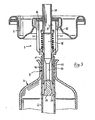
- a first embodiment is shown in three actuation phases of the dispensing valves.
- the standard aerosol valve 3 which is contained in the lid 2 of the outer container 1, comprises a valve housing 32 provided with side windows 31, in which a stem 34, which is tubular at the top and provided with a passage opening 33, is movably arranged and guided.
- a spring 35 presses the stem 34 outward against an elastic sealing washer 36 which, in conjunction with the passage opening 33, forms the actual valve in a known manner. 2 and 4, the valve 3 is closed, shown in FIG. 3 open.
- the valve housing 32 of the dispensing valve 3 has a downward or inwardly projecting tubular extension which forms the valve housing 52 for the dispensing valve 5 of the inner container 4.
- the extension is preferably connected in one piece to the valve housing 32 of the dispensing valve 3.
- a sealing pin 53 In the bottom open end of the tubular extension or the valve housing 52 sits a sealing pin 53, which engages with radially outwardly projecting, cutting-shaped projections 54 into the wall of the riser tube 6 surrounding the entire dispensing valve 5 and thereby holds the sealing pin 53 in its respective position .
- the outer dispensing valve 3 is opened.
- the stem 34 moves inwards (downwards) and, with its extension 37, presses the locking pin 53 out of the housing 52 of the inner valve 5 (FIG. 3).
- the central part 38 of the stem 34 is matched to the inner diameter of the tubular extension 52. In the pressed-in state, it therefore closes the valve housing 52 of the inner valve 5 upward, so that the filling component B located in the inner container 4 does not yet enter the outer container at this time.
- the overflow into the outer container 1 can only take place when the outer valve 3 is completely closed again, since only then the central section 38 of the stem 34 opens the corresponding flow path (FIG. 4).
- the inner container 4 is relatively stable and consists, for example, of glass. It is provided with a dimensionally stable, essentially cylindrical neck 41 which receives the dispensing valve 5. The latter is inserted tightly in the manner of a closure pin with the interposition of an elastic sealing sleeve, which is formed here by the uppermost section 61 of the riser tube 6. The only holder here is the frictional forces between the neck 41 and the sealing sleeve 61 or the housing 52 of the dispensing valve 5. In this way, the otherwise conventional fastening of the valve by means of crimped metal caps or the like can be avoided, so that certain filling goods are chemically aggressive no more problems.
- the main advantage of this type of attachment of the dispensing valve 5 in the inner container 4 is the extremely low The number of construction elements required for this and the extremely easy assembly of the pack. Both properties are for the production cost of a mass. products such as aerosol packs are of crucial importance.
- the direct press-in of the valve with the riser pipe as a sealing sleeve enables relatively small diameters of the opening of the inner container and thus leads to less difficulties with regard to pressure resistance and sealing.
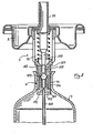
- FIGS. 5-7 show another embodiment of a two-component pack according to the invention, which differs from the embodiment of FIGS. 2-4 essentially only in the type and design of the inner dispensing valve.
- the inner dispensing valve here again comprises a tubular valve housing 152, which is formed by an extension of the housing 32 of the outer valve 3.
- a cylindrical, hollow valve body 153 which is provided with a lateral opening 154, is mounted coaxially in a sealingly displaceable manner. It is closed at the bottom and at its upper end by a sealing pin 39 formed on the stem 34.
- the inner dispensing valve is opened by moving the valve body 153 inward via stem 34.
- An overflow of the contents of the inner container into the outer container can, however, only take place when the outer valve is closed again and the sealing pin 39 has lifted off the valve body 153 (FIG. 7).
- the embodiment shown in Figures 5-7 has the The advantage that it is particularly easy to assemble.
- the diameter of the riser tube 6 cannot be chosen so large that it can be pulled over the entire dispensing valve and used as a sealing sleeve.
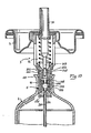
- the embodiment of FIGS. 8-10, in which a separate sealing sleeve 261 is used, is suitable for these cases.
- the riser pipe 260 is inserted here in an insert 255 which closes the valve housing 252 at the bottom and is provided with an axial passage 254.
- This is cage-like and comprises a series of radially resilient rods 256 arranged in a circle, each with an undercut 257 and a bevel 258 on them free ends.
- the rods 256 press a valve ball 259 against the valve seat formed by a shoulder 251 in the valve housing 252 and thereby keep the valve closed.
- the stem 34 of the outer valve 3 has two stepped extensions 237 and 238, the rear (upper), thicker when the dispensing valve 3 is open (i.e. the stem pressed in) comes into contact with a sealing lip 253 in the valve housing 252 and thereby overflows the contents of the inside Prevents container in the outer container with the outer valve open.
- the front (lower), thinner extension 238 pushes the valve ball 259 downward when the outer valve 3 is opened, where it is held by the rods 256 acting as resilient locking means in their undercuts 257 (FIGS. 9, 10). Otherwise, the function of this embodiment variant is analogous to that of the other variants.
- FIGS. 11-13 show an embodiment in which the dispensing valve 5 of the inner container 4 is designed as a piercing valve.
- the valve housing 352 is provided with a dividing wall 353, which can be pierced or pierced by a piercing member 338 fastened or formed on the stem 54 in order to thereby open the inner dispensing valve.
- the valve 5 is fastened with a separate sealing sleeve 361 in the neck 41 of the inner container.
- the riser pipe 6 is inserted directly into a corresponding recess 354 in the valve housing 352.
- the thicker middle section 337 of stem 34 seals with a diaphragm lip 351 at the upper end of valve housing 352.
- This variant has the advantage that the inner container is absolutely tightly closed until the inner dispensing valve is pierced.
Landscapes
- Chemical & Material Sciences (AREA)
- Dispersion Chemistry (AREA)
- Engineering & Computer Science (AREA)
- Mechanical Engineering (AREA)
- Containers And Packaging Bodies Having A Special Means To Remove Contents (AREA)
Abstract
Description
- Die Erfindung betrifft eine Zweikomponentenpackung gemäss Oberbegriff des Patentanspruchs 1.
- Zweikomponentenpackungen dieser Art werden überall dort eingesetzt, wo verschiedene Arten von Füllgut getrennt gelagert werden müssen und erst unmittelbar vor ihrem Gebrauch zusammengebracht werden dürfen. Als Beispiel dafür seien hier nur Haarfärbemittel und dergleichen angeführt.
- Wesentliche Anforderungen an solche Zweikomponentenpackungen sind einerseits konstruktive Einfachheit und damit verbunden niedrige Herstellungskosten und andererseits eine möglichst einfache und sichere Handhabung, wobei gleichzeitig auch eine gute Vermischung der einzelnen Füllgutkomponenten gewährleistet sein muss.
- Für viele Anwendungsarten, so insbesondere auch bei Haarfärbemitteln, ist es wünschenswert oder erforderlich, dass das Füllgut in Aerosol- oder Schaumform abgegeben werden kann. Für diese Anwendungen kommt somit nur eine Aerosol-Zweikomponentenpackung (Spraydose) infrage.
- In der EP-A-24 659 ist eine solche Aerosol-Zweikomponentenpackung beschrieben. Sie umfasst einen äusseren und einen inneren Behälter für je eine Füllgutkomponente und ein Druckgas. Beide Behälter stehen unter demselben Druck. Der innere Behälter ist mittels eines verschiebbaren Kolbens verschlossen. Durch Ablassen eines Teils des Druckgases aus dem äusseren Behälter wird der Kolben im inneren Behälter aufgrund des Druckungleichgewichts verschoben und gibt dabei Kommunikationsöffnungen zum Aussenbehälter frei, so dass sich die Füllgutkomponenten vermischen können.
- Obwohl diese bekannte Zweikomponentenpackung den eingangs erwähnten Anforderungen weitestgehend genügt, hat sich doch gezeigt, dass sie in manchen Punkten, insbesondere in konstruktiver und damit nicht zuletzt auch preislicher Hinsicht noch verbesserungsfähig ist.
- Eine weitere Aerosol-Zweikomponentenpackung ist aus der EP-A-62 817 bekannt. Diese Packung besteht aus zwei ineinander angeordneten kompletten Einkomponenten-Packungen, deren beide Ventile kinematisch so gekoppelt sind, dass beim erstmaligen Betätigen des äusseren Ventils das innere Ventil geöffnet und dann offengehalten wird, wobei sich aufgrund des Ueberdrucks in der inneren Aerosolpackung deren Inhalt in die sie umschliessende äussere Packung ergiesst und sich dort mit dem Inhalt der letzteren vermischt, um dann gemeinsam durch das äussere Ventil entnommen werden zu können.
- Diese bekannte Zweikomponentenpackung weist zwar gegenüber der weiter oben erwähnten Packung gemäss der EP-A-24 659 einige Vorteile auf, ist jedoch immer noch nicht in jeder Hinsicht zufriedenstellend. So ergeben sich u.a. beispielsweise bei chemisch aggressiven Füllgütern Schwierigkeiten mit den bei Standard-Aerosolventilen üblichen metallischen, das Ventil fassenden Deckeln.
- Durch die vorliegende Erfindung soll nun eine zur Abgabe des Füllguts in Aerosolform geeignete Zweikomponentenpackung der zur Rede stehenden Art dahingehend verbessert werden, dass sie den eingangs erwähnten Anforderungen in besonderem Masse gerecht wird. Insbesondere soll die Packung unter Verwendung von möglichst wenigen Einzelteilen möglichst einfach und kostensparend herstellbar sein. Als weitere Forderung soll die Packung Fehlmanipulationen möglichst ausschliessen bzw. sollen Fehlmanipulationen keine nachteiligen Auswirkungen nach sich ziehen.
- Die erfindungsgemässe Zweikomponentenpackung, die dieser der Erfindung zugrundeliegenden Aufgabenstellung genügt, ist in ihren prinzipiellen Merkmalen im Patentanspruch 1 beschrieben. Besonders zweckmässige und vorteilhafte Ausgestaltungen und Weiterbildungen sind in den abhängigen Ansprüchen dargestellt.
- Im folgenden wird die erfindungsgemässe Zweikomponentenpakkung anhand von in der Zeichnung dargestellten Ausführungsbeispielen näher erläutert. Es zeigen:
- Fig.l einen Längsschnitt durch ein prinzipielles Ausführungsbeispiel einer erfindungsgemässen Zweikomponentenpackung und
- Fig.2-13 vergrösserte Detailausschnitte von vier Ausführungsvarianten je in drei verschiedenen Phasen der Ventilbetätigung.
- Die in Fig.1 gezeigte Zweikomponentenpackung umfasst einen äusseren Behälter 1 mit einem Deckel 2 und einem darin gefassten Standard-Aerosol-Abgabeventil3. Im Behälter 1 befinden sich eine erste Füllgutkomponente A und ein innerer Behälter 4, der eine zweite Füllgutkomponente B sowie ein Treibgas T aufnimmt. Der innere Behälter 4 enthält ebenfalls ein Abgabeventil 5 sowie ein Steigrohr 6.
- Soweit entspricht die dargestellte Zweikomponentenpackung in ihrem generellen Aufbau dem Stand der Technik, wie er etwa durch die einleitend diskutierten Druckschriften repräsentiert ist. Der Unterschied gegenüber diesen besteht hauptsächlich in Form, Aufbau und Befestigung des Abgabeventils 5 im inneren Behälter 4 sowie am Abgabeventil 3 des äusseren Behälters 1. Im Detail geht dies aus den ventils 5 im inneren Behälter 4 sowie am Abgabeventil 3 des äusseren Behälters 1. Im Detail geht dies aus den Figuren 2-13 hervor, welche jeweils nur die für die Erfindung wesentlichen Teile einer erfindungegemässen Zweikomponentenpackung zeigen.
- In den Fig. 2-4 ist ein erstes Ausführungsbeispiel in drei Betätigungsphasen der Abgabeventile dargestellt.
- Das im Deckel 2 des äusseren Behälters 1 gefasste Standard-Aerosol-Ventil 3 umfasst ein mit seitlichen Fenstern 31 versehenes Ventilgehäuse 32, in dem axial ein oben rohrförmig ausgebildeter und mit einer Durchlassöffnung 33 versehener Stem 34 beweglich angeordnet und geführt ist. Eine Feder 35 drückt den Stem 34 auswärts gegen eine elastische Dichtungsscheibe 36, welche in Verbindung mit der Durchlassöffnung 33 in bekannter Weise das eigentliche Ventil bildet. In Fig. 2 und 4 ist das Ventil 3 geschlossen, in Fig. 3 geöffnet dargestellt.
- Das Ventilgehäuse 32 des Abgabeventils 3 besitzt eine nach unten bzw. einwärts ragende rohrförmige Verlängerung, die das Ventilgehäuse 52 für das Abgabeventil 5 des inneren Behälters 4 bildet. Die Verlängerung ist vorzugsweise einstückig mit dem Ventilgehäuse 32 des Abgabeventils 3 verbunden. Im unten offenen Ende der rohrförmigen Verlängerung bzw. des Ventilgehäuses 52 sitzt dicht ein Verschlusszapfen 53, der mit radial auswärts ragenden, schneidenförmig ausgebildeten Vorsprüngen 54 in die Wand des das gesamte Abgabeventil 5 umschliessenden Steigrohrs 6 eingreift und dadurch den Verschlusszapfen 53 in seiner jeweiligen Lage festhält.
- Zum Oeffnen des inneren Abgabeventils 5 wird das äussere Abgabeventil 3 geöffnet. Dabei bewegt sich der Stem 34 einwärts (nach unten) und drückt mit seiner Verlängerung 37 den Verschlusszapfen 53 aus dem Gehäuse 52 des inneren Ventils 5 heraus (Fig.3). Der Mittelteil 38 des Stems 34 ist auf den Innendurchmesser der rohrförmigen Verlängerung 52 abgestimmt. Im eingedrückten Zustand verschliesst er daher das Ventilgehäuse 52 des inneren Ventils 5 nach oben, sodass die im inneren Behälter 4 befindliche Füllgutkomponente B zu diesem Zeitpunkt noch nicht in den äusseren Behälter.-1 und von da (unerwünschterweise) durch das offene äussere Abgabeventil 3 nach aussen entweichen kann. Das Ueberströmen in den äusseren Behälter 1 kann erst erfolgen, wenn das äussere Ventil 3 wieder vollständig geschlossen ist, da erst dann der Mittelabschnitt 38 des Stem34 den entsprechenden Strömungsweg freigibt (Fig.4).
- Der innere Behälter 4 ist relativ formstabil aufgebaut und besteht z.B. aus Glas. Er ist mit einem formstabilen, im wesentlichen zylindrischen Hals 41 versehen, der das Abgabeventil 5 aufnimmt. Letzteres ist in diesen unter Zwischenlage einer elastischen Dichtunghülse, die hier durch den obersten Abschnitt 61 des Steigrohrs 6 gebildet wird, dicht nach Art eines Verschlusszapfens eingesetzt. Einzige Halterung bilden dabei die Reibungskräfte zwischen dem Hals 41 und der Dichtungshülse 61 bzw. dem Gehäuse 52 des Abgabeventils 5. Auf diese Weise kann die sonst übliche Befestigung des Ventils mittels gecrimpter Metallkappen oder dgl. vermieden werden, sodass sich bezüglich der chemischen Aggressivität gewisser Füllgüter keine Schwierigkeiten mehr ergeben. Der Hauptvorteil dieser Befestigungsart des Abgabeventils 5 im inneren Behälter 4 besteht in der extrem niedrigen Anzahl von dazu erforderlichen Konstruktionselementen sowie der extrem leichten Montierbarkeit der Packung. Beide Eigenschaften sind für die Produktionskosten eines Massen. produkte, wie es Aerosolpackungen sind, von ausschlaggebender Bedeutung. Ausserdem ermöglicht die direkte Einpressung des Ventils mit dem Steigrohr als Dichtungshülse relativ kleine Durchmesser der Oeffnung des inneren Behälters und führt damit zu weniger Schwierigkeiten hinsichtlich Druckfestigkeit und Abdichtung.
- Die Figuren 5-7 zeigen eine andere Ausführungsform einer erfindungsgemässen Zweikomponentenpackung, die sich im wesentlichen nur durch die Art und Ausbildung des inneren Abgabeventils von der Ausführungsform der Figuren 2-4 unterscheidet.
- Das innere Abgabeventil umfasst hier wieder ein rohrförmiges Ventilgehäuse 152, das durch eine Verlängerung des Gehäuses 32 des äusseren Ventils 3 gebildet ist. Im Abgabeventilgehäuse 152 ist koaxial ein zylindrischer, hohler, mit einer seitlichen Oeffnung 154 versehener Ventilkörper 153 dichtend auf- und ab verschiebbar gelagert. Er ist unten zu und an seinem oberen Ende durch einen am Stem 34 ausgebildeten Dichtzapfen 39 verschlossen.
- Wie Fig. 6 zeigt, wird das innere Abgabeventil durch Einwärtsverschiebung des Ventilkörpers 153 via Stem 34 geöffnet. Ein Ueberströmen des Inhalts des inneren Behälters in den äusseren Behälter kann jedoch erst erfolgen, wenn wenn das äussere Ventil wieder geschlossen ist und der Dichtzapfen 39 vom Ventilkörper 153 abgehoben hat (Fig.7).
- Die in den Figuren 5-7 gezeigte Ausführungsvariante hat den Vorteil, dass sie sich besonders einfach zusammenbauen lässt.
- In gewissen Fällen kann der Durchmesser des Steigrohrs 6 nicht so gross gewählt werden, dass es über das gesamte Abgabeventil gezogen und als Dichtungshülse verwendet werden kann. Für diese Fälle ist die Ausführungsform der Figuren 8-10 geeignet, bei der eine gesonderte Dichtungshülse 261 verwendet wird. Das Steigrohr 260 steckt hier in einem das Ventilgehäuse 252 unten verschliessenden und mit einem axialen Durchlass 254 versehenen Einsatz 255. Dieser ist käfigartig ausgebildet und umfasst eine Reihe von im Kreis angeordneten, radial federnden Staben 256 mit je einer Hinterschneidung 257 und einer Abschrägung 258 an ihren freien Enden. Die Stäbe 256 drücken eine Ventilkugel 259 gegen den durch eine Schulter 251 im Ventilgehäuse 252 gebildeten Ventilsitz und halten das Ventil dadurch geschlossen.
- Der Stem 34 des äusseren Ventils 3 besitzt zwei abgestufte Verlängerungen 237 und 238, deren hintere (obere), dickere bei geöffnetem Abgabeventil 3 (also einwärts gedrücktem Stem) mit einer Dichtlippe 253 im Ventilgehäuse 252 in Anlage kommt und dadurch ein Ueberströmen des Inhalts des inneren Behälters in den äusseren Behälter bei geöffnetem äusseren Ventil verhindert. Die vordere (untere), dünnere Verlängerung 238 stösst beim Oeffnen des äusseren Ventils 3 die Ventilkugel 259 nach unten, wo sie von den als federnde Rastmittel wirkenden Stäben 256 in deren Hinterschneidungen 257 festgehalten wird (Fig.9,10). Im übrigen ist die Funktion dieser Ausführungsvariante analog der der anderen Varianten.
- Die Figuren 11-13 zeigen ein Ausführungsbeispiel, bei dem das Abgabeventil 5 des inneren Behälters 4 als Aufstoch-Ventil ausgobildet ist. Hier ist das Ventilgehäuse 352 mit einer Trennwand 353 versehen, welche von einem am Stem 54 befestigten bzw. ausgebildeten Aufstechorgan 338 durchstochen bzw. durchbrochen werden kann, um das innere Abgabeventil dadurch zu öffnen. Das Ventil 5 ist, wie beim vorstehenden Ausführungsbeispiel, mit einer separaten Dichtungshülse 361 im Hals 41 des inneren Behälters befestigt. Das Steigrohr 6 steckt direkt in einer entsprechenden Ausnohmung 354 des Ventilgehäuses 352.
- Während der Aufstechphase (Fig.12) dichtet der dicker ausgebildete, mittlere Abschnitt 337 des Stems 34 mit einer Diohtlippe 351 am oberen Ende des Ventilgehäuses 352 ab.
- Diese Variante hat den Vorteil, dass der innere Behälter bis zum Aufstechen des inneren Abgabeventils absolut dicht geschlossen ist.
Claims (12)
dadurch gekennzeichnet, dass
der innere Behälter (4) mit einem im wesentlichen formstabilen Hals (41) versehen ist und dass sein Abgabeventil(5) mittels einer es umschliessenden elastischen Dichtungshülse (61) nach Art eines Verschlusszapfens dicht und im wesentlichen unbeweglich in den Hals (41) des inneren Behälters (4) eingesetzt ist.
Applications Claiming Priority (2)
| Application Number | Priority Date | Filing Date | Title |
|---|---|---|---|
| CH418983 | 1983-08-02 | ||
| CH4189/83 | 1983-08-02 |
Publications (3)
| Publication Number | Publication Date |
|---|---|
| EP0132511A2 true EP0132511A2 (de) | 1985-02-13 |
| EP0132511A3 EP0132511A3 (en) | 1985-03-13 |
| EP0132511B1 EP0132511B1 (de) | 1986-10-15 |
Family
ID=4271451
Family Applications (1)
| Application Number | Title | Priority Date | Filing Date |
|---|---|---|---|
| EP19840104588 Expired EP0132511B1 (de) | 1983-08-02 | 1984-04-24 | Zweikomponentenpackung |
Country Status (2)
| Country | Link |
|---|---|
| EP (1) | EP0132511B1 (de) |
| DE (1) | DE3460955D1 (de) |
Cited By (8)
| Publication number | Priority date | Publication date | Assignee | Title |
|---|---|---|---|---|
| US4666062A (en) * | 1984-02-13 | 1987-05-19 | F.P.D. Future Patents Development Company S.A. | Device for mixing and spraying a mixture composed of at least two components, such as liquids, and a propellant |
| US5040704A (en) * | 1990-01-26 | 1991-08-20 | Ccl Industries, Inc. | Method and apparatus for dispensing product from a product bag |
| WO2011141069A3 (de) * | 2010-04-15 | 2012-01-05 | Henkel Ag & Co. Kgaa | Verfahren zur herstellung eines färbemittels für keratinfasern |
| WO2012052198A1 (de) * | 2010-10-20 | 2012-04-26 | Henkel Ag & Co. Kgaa | Verfahren zur herstellung eines färbemittels für keratinfasern |
| WO2012052197A1 (de) * | 2010-10-20 | 2012-04-26 | Henkel Ag & Co. Kgaa | Verfahren zur herstellung eines färbemittels für keratinfasern |
| WO2012052195A1 (de) * | 2010-10-20 | 2012-04-26 | Henkel Ag & Co. Kgaa | Verfahren zur herstellung eines färbemittels für keratinfasern |
| WO2012052196A1 (de) * | 2010-10-20 | 2012-04-26 | Henkel Ag & Co. Kgaa | Verfahren zur herstellung eines färbemittels |
| CN113226566A (zh) * | 2018-11-26 | 2021-08-06 | 分配技术有限公司 | 分配液体与添加剂的混合物的系统和方法及其中使用的筒 |
Family Cites Families (4)
| Publication number | Priority date | Publication date | Assignee | Title |
|---|---|---|---|---|
| FR1593123A (de) * | 1967-12-22 | 1970-05-25 | ||
| IT1092070B (it) * | 1978-01-20 | 1985-07-06 | Coster Tecnologie Speciali Spa | Valvola per l'erogazione separata di due componenti e per la loro miscelazione all'esterno della stessa |
| US4340155A (en) * | 1979-08-24 | 1982-07-20 | Aerosol Service Ag | Two-compartment pack |
| US4469252A (en) * | 1981-04-10 | 1984-09-04 | Aerosol Service Ag | Two-compartment package |
-
1984
- 1984-04-24 DE DE8484104588T patent/DE3460955D1/de not_active Expired
- 1984-04-24 EP EP19840104588 patent/EP0132511B1/de not_active Expired
Cited By (13)
| Publication number | Priority date | Publication date | Assignee | Title |
|---|---|---|---|---|
| US4666062A (en) * | 1984-02-13 | 1987-05-19 | F.P.D. Future Patents Development Company S.A. | Device for mixing and spraying a mixture composed of at least two components, such as liquids, and a propellant |
| US5040704A (en) * | 1990-01-26 | 1991-08-20 | Ccl Industries, Inc. | Method and apparatus for dispensing product from a product bag |
| WO2011141069A3 (de) * | 2010-04-15 | 2012-01-05 | Henkel Ag & Co. Kgaa | Verfahren zur herstellung eines färbemittels für keratinfasern |
| US8673023B2 (en) | 2010-04-15 | 2014-03-18 | Henkel Ag & Co. Kgaa | Method for preparing a coloring composition |
| WO2012052196A1 (de) * | 2010-10-20 | 2012-04-26 | Henkel Ag & Co. Kgaa | Verfahren zur herstellung eines färbemittels |
| WO2012052195A1 (de) * | 2010-10-20 | 2012-04-26 | Henkel Ag & Co. Kgaa | Verfahren zur herstellung eines färbemittels für keratinfasern |
| WO2012052197A1 (de) * | 2010-10-20 | 2012-04-26 | Henkel Ag & Co. Kgaa | Verfahren zur herstellung eines färbemittels für keratinfasern |
| US8545576B2 (en) | 2010-10-20 | 2013-10-01 | Henkel Ag & Co., Kgaa | Process for producing a colorant for keratin fibers |
| US8545575B2 (en) | 2010-10-20 | 2013-10-01 | Henkel Ag & Co. Kgaa | Process for producing a colorant for keratin fibers |
| US8551190B2 (en) | 2010-10-20 | 2013-10-08 | Henkel Ag & Co. Kgaa | Process for producing a colorant for keratin fibers |
| WO2012052198A1 (de) * | 2010-10-20 | 2012-04-26 | Henkel Ag & Co. Kgaa | Verfahren zur herstellung eines färbemittels für keratinfasern |
| CN113226566A (zh) * | 2018-11-26 | 2021-08-06 | 分配技术有限公司 | 分配液体与添加剂的混合物的系统和方法及其中使用的筒 |
| CN113226566B (zh) * | 2018-11-26 | 2024-04-09 | 分配技术有限公司 | 分配液体与添加剂的混合物的系统和方法及其中使用的筒 |
Also Published As
| Publication number | Publication date |
|---|---|
| EP0132511A3 (en) | 1985-03-13 |
| DE3460955D1 (en) | 1986-11-20 |
| EP0132511B1 (de) | 1986-10-15 |
Similar Documents
| Publication | Publication Date | Title |
|---|---|---|
| EP0062817B1 (de) | Zweikammerpackung | |
| DE69203591T2 (de) | In umgekehrter Lage verwendbares Dosierventil. | |
| DE69009754T2 (de) | Dosierventil für aerosolbehälter. | |
| DE69904234T2 (de) | Behälter zum abgeben von flüssigkeit mit einer druckkontrollvorrichtung und aktivierungseinheit | |
| EP0806344B1 (de) | Verfahren zum rückseitigen Befüllen eines Klebstoffspenders und Klebstoffspender zum Ausführen des Verfahrens | |
| DE1916093C3 (de) | Ventil zum Ausgeben eines Mate nalgemisches aus mehreren Behaltern | |
| CH617146A5 (de) | ||
| DE214012T1 (de) | Vorrichtung zur abgabe abgemessener mengen mindestens eines relativ dickfluessigen produktes. | |
| DE1400733B2 (de) | Einrichtung für die Abgabe von dosierten Teilmengen eines in einem Behälter befindlichen Füllgutes | |
| DE1817260A1 (de) | Mit einem Druck erzeugenden Treibmittel arbeitende Abgabevorrichtung | |
| DE602005004152T3 (de) | Spender für ein flüssigprodukt | |
| EP0132511B1 (de) | Zweikomponentenpackung | |
| DE69714025T2 (de) | Verteilungseinrichtung einer einmaligen dosis eines flüssigen produktes | |
| DE2362376A1 (de) | Ventilanordnung fuer druckbehaelter | |
| EP0152761A2 (de) | Vorrichtung zum Herstellen und Versprühen einer aus wenigstens zwei Komponenten, z.B. Flüssigkeiten, und einem Treibgas bestehenden Mischung | |
| DE10351565A1 (de) | Selbstschließender Fluidspendeverschluss | |
| EP0137897A1 (de) | Zweikomponentenpackung | |
| DE3405064A1 (de) | Vorrichtung zum herstellen und verspruehen einer aus wenigstens zwei komponenten, z. b. fluessigkeiten, und einem treibgas bestehenden mischung | |
| EP0269068A2 (de) | Aerosol-Verpackung | |
| DE1929844A1 (de) | Geraet zum Abgeben von Verbrauchsstoffen,z.B. Rasierkrem | |
| DE3528525A1 (de) | Doppelkammer-behaelter | |
| DE602004003951T2 (de) | Steuerventil für einen fluidproduktspender und solch ein ventil umfassender fluidproduktspender | |
| DE602004008340T2 (de) | Fluidproduktspender | |
| DE1959809A1 (de) | Dose zum Vermischen und Ausgeben von zwei Materialien | |
| DE20015613U1 (de) | Zweikomponentenspender |
Legal Events
| Date | Code | Title | Description |
|---|---|---|---|
| PUAI | Public reference made under article 153(3) epc to a published international application that has entered the european phase |
Free format text: ORIGINAL CODE: 0009012 |
|
| PUAL | Search report despatched |
Free format text: ORIGINAL CODE: 0009013 |
|
| 17P | Request for examination filed |
Effective date: 19840601 |
|
| AK | Designated contracting states |
Designated state(s): BE CH DE FR GB IT LI NL |
|
| AK | Designated contracting states |
Designated state(s): BE CH DE FR GB IT LI NL |
|
| GRAA | (expected) grant |
Free format text: ORIGINAL CODE: 0009210 |
|
| AK | Designated contracting states |
Kind code of ref document: B1 Designated state(s): BE CH DE FR GB IT LI NL |
|
| REF | Corresponds to: |
Ref document number: 3460955 Country of ref document: DE Date of ref document: 19861120 |
|
| ET | Fr: translation filed | ||
| ITF | It: translation for a ep patent filed | ||
| PGFP | Annual fee paid to national office [announced via postgrant information from national office to epo] |
Ref country code: NL Payment date: 19870430 Year of fee payment: 4 |
|
| PLBE | No opposition filed within time limit |
Free format text: ORIGINAL CODE: 0009261 |
|
| STAA | Information on the status of an ep patent application or granted ep patent |
Free format text: STATUS: NO OPPOSITION FILED WITHIN TIME LIMIT |
|
| 26N | No opposition filed | ||
| PG25 | Lapsed in a contracting state [announced via postgrant information from national office to epo] |
Ref country code: LI Effective date: 19880430 Ref country code: CH Effective date: 19880430 |
|
| BERE | Be: lapsed |
Owner name: AEROSOL-SERVICE A.G. Effective date: 19880430 |
|
| PG25 | Lapsed in a contracting state [announced via postgrant information from national office to epo] |
Ref country code: NL Effective date: 19881101 |
|
| NLV4 | Nl: lapsed or anulled due to non-payment of the annual fee | ||
| REG | Reference to a national code |
Ref country code: CH Ref legal event code: PL |
|
| PG25 | Lapsed in a contracting state [announced via postgrant information from national office to epo] |
Ref country code: DE Effective date: 19890103 |
|
| PG25 | Lapsed in a contracting state [announced via postgrant information from national office to epo] |
Ref country code: GB Effective date: 19890424 |
|
| PG25 | Lapsed in a contracting state [announced via postgrant information from national office to epo] |
Ref country code: BE Effective date: 19890430 |
|
| GBPC | Gb: european patent ceased through non-payment of renewal fee | ||
| PG25 | Lapsed in a contracting state [announced via postgrant information from national office to epo] |
Ref country code: FR Free format text: LAPSE BECAUSE OF NON-PAYMENT OF DUE FEES Effective date: 19891228 |
|
| REG | Reference to a national code |
Ref country code: FR Ref legal event code: ST |