EP0132533A2 - Behälter für die Aufbewahrung von Magnetbandkassetten - Google Patents
Behälter für die Aufbewahrung von Magnetbandkassetten Download PDFInfo
- Publication number
- EP0132533A2 EP0132533A2 EP84105978A EP84105978A EP0132533A2 EP 0132533 A2 EP0132533 A2 EP 0132533A2 EP 84105978 A EP84105978 A EP 84105978A EP 84105978 A EP84105978 A EP 84105978A EP 0132533 A2 EP0132533 A2 EP 0132533A2
- Authority
- EP
- European Patent Office
- Prior art keywords
- container
- light
- wall parts
- guide rods
- light guide
- Prior art date
- Legal status (The legal status is an assumption and is not a legal conclusion. Google has not performed a legal analysis and makes no representation as to the accuracy of the status listed.)
- Granted
Links
Images

Classifications
-
- G—PHYSICS
- G11—INFORMATION STORAGE
- G11B—INFORMATION STORAGE BASED ON RELATIVE MOVEMENT BETWEEN RECORD CARRIER AND TRANSDUCER
- G11B23/00—Record carriers not specific to the method of recording or reproducing; Accessories, e.g. containers, specially adapted for co-operation with the recording or reproducing apparatus ; Intermediate mediums; Apparatus or processes specially adapted for their manufacture
- G11B23/02—Containers; Storing means both adapted to cooperate with the recording or reproducing means
- G11B23/023—Containers for magazines or cassettes
Definitions
- the invention relates to a container with one or more individual boxes, which consist of a rectangular hollow body wall parts and a slide which holds a magnetic tape cassette and has a front fitting in the hollow body.
- the invention is therefore based on the object of providing an orientation aid which, even in the absence of illumination, makes it possible to locate and actuate the slides for removing magnetic tape cassettes.
- this is achieved in that a reflector equipped with a light source is arranged on the rear of the container and in that the wall parts are made of light-conducting plastic.
- the entire back of the container is illuminated with the reflector and the built-in light source.
- the wall parts made of light-conducting plastic, there is a light band corresponding to the front contour of the wall parts, which frames the individual boxes. Since the front of the slide to be operated to open the box lies within the light band, finding the individual boxes is no longer a problem.
- the reflector can form the back of the container.
- the reflector is an integral part of the housing of the container.
- the reflector can be an injection-molded part consisting of bright, preferably white-colored plastic.
- the reflection of a light or white colored plastic reflector is sufficient to generate a sufficient light band on the front of the housing even with a relatively weak power source.
- the light source can be connected to the circuit that feeds the dashboard lighting.
- a grid can be placed on the back of the container in a container composed of a plurality of individual boxes stackable by means of connecting strips and slots arranged on the wall parts such that its slot-like openings save the wall parts which do not have any connecting slots.
- the connecting slots and connecting bars of the wall parts of the individual boxes which engage in these slots can result in shadows forming on the front of the light strip, which make an unaesthetic impression.
- the light source can be formed from light guide rods arranged in a lattice arrangement, which run along the wall parts made of light-conducting plastic and are fed by a lighting fixture arranged outside the reflector.
- the light guide rods fed by the lighting fixture arranged outside the reflector cause a transpa wall parts concentrated and even light distribution.
- the height of the reflector is determined by the thickness of the light guide rods.
- the light entry sides of the light guide rods can be grouped in a star shape around the lighting fixture. Multiple strands of the light guide rods, which extend separately from the lighting fixture, result in lower light losses for the wall parts of the container which are further away from the lighting fixture, so that the more intensive use of the light generated by the lighting fixture produces a uniform light band on the front side of the container.
- a cap with openings arranged in a star shape can be placed over the lighting fixture, into which the light entry side of the light guide rods open. A further improvement in efficiency is achieved with the cap placed over the lighting fixture.
- the outer surface of the light guide rods facing the wall parts can be activated by roughening. This means that the light emission from the light guide rods is concentrated even more strongly on the wall parts made of light-conducting plastic.
- the invention can be implemented in a further embodiment the roughening of the light guide rods increases with increasing distance from the lighting fixture in their roughness.
- the light emission is increased by increasing the roughness, so that uniform illumination takes place regardless of the distance of the wall parts from the lighting fixture.
- each individual box has a forward-opening closure in the form of a front plate 3 arranged on the slide, upon actuation of which the cassette is conveyed out of the box by means of the slide.
- the housing of the individual boxes 2 consists of wall parts 4 forming a rectangular hollow body, the upper side having connecting strips 5 and the lower side having connecting slots 6 corresponding to these strips.
- the rear of the container housing 1 is formed by a reflector 7, which consists of a white colored plastic part.
- a light bulb 8 is provided in the center of the reflector 7 and can be connected, for example, to the circuit of the dashboard lighting of a motor vehicle.
- the entire rear side of the container and thus the wall parts 4 of the individual boxes made of a light-conducting plastic are irradiated by the reflector 7.
- the light is directed bundled over the wall parts 4 to the front of the boxes, where it identifies the outlines of the individual boxes as a light band.
- the interlocking connecting strips 5 and slots 6 of the individual boxes 2 would result in differences in brightness which impair the optics.
- a grid 10 provided with slot-like openings is placed on the back of the boxes in such a way that the wall parts of the boxes provided with the connecting means are covered.
- the openings 9 of the grating 10 thus allow light to enter the areas of the wall parts 4 which have no interruptions. This means that a uniform light band appears on the front, showing the outlines of the boxes.
- the lighting element 8 is provided on the side of the container. From this lighting fixture 8, several strands of light guide rods 11 extend in a star shape, which run along the wall parts 4 made of light-conducting plastic in a lattice shape.
- the light guide rods 11 are activated by a roughening of their lateral surface facing the wall parts, so that the light is directed bundled over the wall parts 4 to the front of the boxes, where it identifies the contours of the individual boxes as a light band.
- the interlocking connecting strips 5 and slots 6 of the individual boxes 2 would result in differences in brightness which impair the optics.
- a grid 10 provided with slot-like openings 9 is placed on the back of the box in such a way that the ver see wall parts 4 of the boxes are covered.
- the openings 9 of the grating 10 thus allow light to enter the area of the wall parts 4 which have no interruptions. This means that a uniform band of light appears on the front, showing the outlines of the boxes.
- a cap 12 with openings 13 arranged in a star shape is placed on the lighting fixture, into which the light entry side 14 of the light guide rods 11 open.
- the uniform distribution of the light is favored by roughening the jacket surface of the light guide rods 11 facing the wall parts, the roughness depth of the roughening also increasing with increasing distance from the lighting fixture 8.
Landscapes
- Arrangements Of Lighting Devices For Vehicle Interiors, Mounting And Supporting Thereof, Circuits Therefore (AREA)
- Vehicle Step Arrangements And Article Storage (AREA)
Abstract
Description
- Die Erfindung betrifft einen Behälter mit ein oder mehreren Einzelboxen, die aus einen rechteckigen Hohlkörper bildenden Wandteilen und einem eine in den Hohlkörper passende Frontseite aufweisenden, eine Magnetbandkassette haltenden Schieber bestehen.
- Wird der Behälter bei ausreichender Beleuchtung verwendet, bestehen keine Schwierigkeiten, den zum öffnen des Behälters für die Ent- nahme der Kassette zu betätigenden Schieber aufzufinden. Bei . fehlender Ausleuchtung insbesondere im Kraftfahrzeug bei Nachtfahrten sind Orientierungshilfen zweckmäßig.
- Der Erfindung liegt daher die Aufgabe zugrunde, eine Orientierungshilfe zu schaffen, die auch bei fehlender Ausleuchtung das Auffinden und die Betätigung der Schieber zur Entnahme von Magnetbandkassetten ermöglicht.
- Erfindungsgemäß wird dies dadurch erreicht, daß an der Rückseite des Behälters ein mit einer Lichtquelle ausgestatteter Reflektor angeordnet ist, und daß die Wandteile aus lichtleitendem Kunststoff hergestellt sind.
- Mit dem Reflektor und der eingebauten Lichtquelle wird die gesamte Rückseite des Behälters angestrahlt. Ober die aus lichtleitendem Kunststoff bestehenden Wandteile ergibt sich ein der frontseitigen Kontur der Wandteile entsprechendes Lichtband, das die Einzelboxen umrahmt. Da die Frontseite des zum öffnen der Box zu betätigenden Schiebers innerhalb des Lichtbandes - liegt, stellt das Auffinden der einzelnen Boxen kein Problem mehr dar.
- In einer weiteren Ausgestaltung der Erfindung kann der Reflektor die Rückseite des Behälters bilden. Mit dieser Gestaltung ist der Reflektor integrierter Bestandteil des Gehäuses des Behälters.
- In einer weiteren Ergänzung der Erfindung kann der Reflektor ein aus hell, vorzugsweise weiß eingefärbtem Kunststoff bestehendes Spritzteil sein. Die Reflexion eines hell bzw. weiß eingefärbten Kunststoffreflektors reicht aus, um auch bei relativ schwacher Stromquelle an der Frontseite des Gehäuses ein ausreichendes Lichtband zu erzeugen.
- Schließlich kann in einer weiteren Ergänzung der Erfindung bei einem Einsatz des Behälters in Kraftfahrzeugen die Lichtquelle an den die Armaturenbeleuchtung speisenden Stromkreis angeschlossen sein.
- Schließlich kann in weiterer Ergänzung der Erfindung bei einem aus mehreren mittels an den Wandteilen angeordneten Verbindungsleisten und -schlitzen stapelbaren Einzelboxen zusammengestellten Behälter auf die Rückseite des Behälters ein Gitter derart aufgelegt sein, daß dessen schlitzartigen Öffnungen die Wandteile freisparen, die keine Verbindungsschlitze aufweisen. Durch die Verbindungsschlitze und in diese Schlitze eingreifenden Verbindungsleisten der Wandteile der Einzelboxen können sich an der Frontseite des Lichtbandes durch.Helligkeitsunterschiede Schattenbildungen ergeben, die einen unästhetischen Eindruck machen. Durch die Abdeckung der die Helligkeitsunterschiede verursachenden Verbindungselemente wird ein gleichmäßiges Lichtband an der Frontseite erreicht.
- In einer weiteren Ergänzung der Erfindung kann die Lichtquelle aus gitterförmig angeordneten Lichtleitstäben gebildet sein, die entlang den aus lichtleitendem Kunststoff bestehenden Wandteilen verlaufen und durch eine außerhalb des Reflektors angeordneten Beleuchtungskörper gespeist sind.
- Die von dem außerhalb des Reflektors angeordneten Beleuchtungskörper gespeisten Lichtleitstäbe bewirken eine auf die transparenten Wandteile konzentrierte und gleichmäßige Lichtverteilung. Die Bauhöhe des Reflektors wird dabei von der Dicke der Lichtleitstäbe bestimmt. Die sich damit ergebende relativ flache Bauweise des Behälters erleichtert den Einbau insbesondere in Kraftfahrzeugen, wo sehr häufig nur begrenzte Einbautiefen zur Verfügung stehen.
- In einer weiteren Ausgestaltung der Erfindung können die Lichteintrittsseiten der Lichtleitstäbe sternförmig um den Beleuchtungskörper gruppiert sein. Durch mehrere, separat vom Beleuchtungskörper abgehende Stränge der Lichtleitstäbe ergeben sich geringere Lichtverluste für die vom Beleuchtungskörper entfernt liegenderen Wandteilen des Behälters, sodaß durch die intensivere Ausnutzung des durch den Beleuchtungskörper erzeugten Lichts ein gleichmäßiges Lichtband an der Frontseite des Behälters erzeugt wird.
- In einer weiteren Gestaltung der Erfindung kann über den Beleuchtungskörper eine Kappe mit sternförmig angeordneten Öffnungen gestülpt sein, in die die Lichteintrittsseite der Lichtleitstäbe münden. Mit der über den Beleuchtungskörper gestülpten Kappe wird eine weitere Wirkungsgradverbesserung erreicht.
- Schließlich kann nach einer weiteren Ergänzung der Erfindung die den Wandteilen zugekehrte Mantelfläche der Lichtleitstäbe durch eine Aufrauhung aktiviert sein. Damit wird der Lichtaustritt der Lichtleitstäbe auf die aus lichtleitendem Kunststoff bestehenden Wandteile noch stärker konzentriert.
- Um die auftretenden Lichtverluste in den Lichtleitstäben in Abhängigkeit von der Entfernung vom Beleuchtungskörper zu kompensieren, kann in weiterer Ausgestaltung der Erfindung die Aufrauhung der Lichtleitstäbe mit zunehmendem Abstand vom Beleuchtungskörper in ihrer Rauhtiefe zunehmen. Durch Erhöhung der Rauhtiefe wird der Lichtaustritt verstärkt, sodaß unabhängig vom Abstand der Wandteile vom Beleuchtungskörper eine gleichmäßige Ausleuchtung stattfindet.
- In der Zeichnung ist ein Ausführungsbeispiel der Erfindung dargestellt.
- Es zeigen:
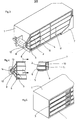
- Figur 1 den Behälter in perspektivischer Darstellung mit aufgeschnittenem Reflektor
- Figur 2 die Frontseite des Behälters
- Figur 3 den Behälter mit seitlich angebrachtem Beleuchtungskörper
- Figur 4 eine Teilansicht der Rückseite des Behälters nach Figur 3
- Figur 5 eine Teilansicht der Frontseite des Behälters nach Figur 3.
- In das Behältergehäuse 1 nach Fig. 1 und 2 sind mehrere, jeweils zu zwei Blöcken zusammengefaßte Einzelboxen 2 eingeschoben. Jede einzelne Box weist einen nach vorn öffnenden Verschluß in Form einer am Schieber angeordneten Frontplatte 3 auf, bei dessen Betätigung die Kassette mittels des Schiebers aus der Box herausbefördert wird. Das Gehäuse der Einzelboxen 2 besteht aus einen rechteckigen Hohlkörper bildenden Wandteilen 4, wobei die Oberseite Verbindungsleisten 5 und die Unterseite mit diesen Leisten korrespondierende Verbindungsschlitze 6 aufweist.
- Die Rückseite des Behältergehäuses 1 wird durch einen Reflektor 7 gebildet, der aus einem weiß eingefärbten Kunststoffteil besteht. Im Zentrum des Reflektors 7 ist eine Glühbirne 8 vorgesehen, die beispielsweise an den Stromkreis der Armaturenbeleuchtung eines Kraftfahrzeuges anschließbar ist. Durch den Reflektor 7 wird die gesamte Rückseite des Behälters und damit die Wandteile 4 der einzelnen, aus einem lichtleitendem Kunststoff hergestellten Boxen bestrahlt. Ober die Wandteile 4 wird das Licht gebündelt an die Frontseite der Boxen geleitet, wo es als Lichtband die Umrisse der einzelnen Boxen kenntlich macht. Durch die ineinandergreifenden Verbindungsleisten 5 und -schlitze 6 der Einzelboxen 2 würden die Optik beeinträchtigende Helligkeitsunterschiede entstehen. Um dies zu vermeiden ist auf die Rückseite der Boxen ein mit schlitzartigen öffnungen versehenes Gitter 10 derart aufgelegt, daß die mit den Verbindungsmitteln versehenen Wandteiie der Boxen abgedeckt sind. Die Öffnungen 9 des Gitters 10 ermöglichen somit einen Lichteinfall auf die Bereiche der Wandungsteile 4, die keine Unterbrechungen aufweisen. Damit erscheint auf der Frontseite ein gleichmäßiges, die Umrisse der Boxen abzeichnendes Lichtband.
- Bei dem Ausführungsbeispiel nach den Figuren 3,4 und 5 ist der Beleuchtungskörper 8 seitlich am Behälter vorgesehen. Von diesem Beleuchtungskörper 8 gehen sternförmig mehrere Stränge von Lichtleitstäben 11 ab, die gitterförmig entlang den aus lichtleitendem Kunststoff bestehenden Wandteilen 4 verlaufen. Die Lichtleitstäbe 11 sind durch eine den Wandteilen zugekehrte Aufrauhung ihrer Mantelfläche aktiviert, sodaß über die Wandteile 4 das Licht gebündelt an die Frontseite der Boxen geleitet wird, wo es als Lichtband die Umrisse der einzelnen Boxen kenntlich macht. Durch die ineinandergreifenden Verbindungsleisten 5 und -schlitze 6 der Einzelboxen 2 würden die Optik beeinträchtigende Helligkeitsunterschiede entstehen. Um dies zu vermeiden, ist auf die Rückseite der Box ein mit schlitzartigen öffnungen 9 versehenes Gitter 10 derart aufgelegt, daß die mit den Versehenen Wandteile 4 der Boxen abgedeckt sind. Die öffnungen 9 des Gitters 10 ermöglichen somit einen Lichteinfall auf die Bereich der Wandungsteile 4, die keine Unterbrechungen aufweisen. Damit erscheint auf der Frontseite ein gleichmäßiges, die Umrisse der Boxen abzeichnendes Lichtband.
- Um bezüglich der Ausnutzung des vorhandenen Lichts einen noch besseren Wirkungsgrad zu erreichen, ist auf den Beleuchtungskörper eine Kappe 12 mit sternförmig angeordneten üffnungen 13 gestülpt, in die die Leichteintrittsseite 14 der Lichtleitstäbe 11 münden. Begünstigt wird die gleichmäßige Verteilung des Lichts durch eine Aufrauhung der den Wandteilen zugekehrten Mantelffäche der Lichtleitstäbe 11, wobei die Rautiefe der Aufrauhung mit zunehmenden Abstand von Beleuchtungskörper 8 ebenfalls zunimmt.
Claims (10)
Priority Applications (1)
| Application Number | Priority Date | Filing Date | Title |
|---|---|---|---|
| AT84105978T ATE38578T1 (de) | 1983-07-22 | 1984-05-25 | Behaelter fuer die aufbewahrung von magnetbandkassetten. |
Applications Claiming Priority (4)
| Application Number | Priority Date | Filing Date | Title |
|---|---|---|---|
| DE19833326465 DE3326465A1 (de) | 1983-07-22 | 1983-07-22 | Behaelter fuer die aufbewahrung von magnetbandkassetten |
| DE3326465 | 1983-07-22 | ||
| DE19833338518 DE3338518A1 (de) | 1983-10-22 | 1983-10-22 | Behaelter fuer die aufbewahrung von magnetbandkassetten |
| DE3338518 | 1983-10-22 |
Publications (3)
| Publication Number | Publication Date |
|---|---|
| EP0132533A2 true EP0132533A2 (de) | 1985-02-13 |
| EP0132533A3 EP0132533A3 (en) | 1985-12-11 |
| EP0132533B1 EP0132533B1 (de) | 1988-11-09 |
Family
ID=25812534
Family Applications (1)
| Application Number | Title | Priority Date | Filing Date |
|---|---|---|---|
| EP19840105978 Expired EP0132533B1 (de) | 1983-07-22 | 1984-05-25 | Behälter für die Aufbewahrung von Magnetbandkassetten |
Country Status (4)
| Country | Link |
|---|---|
| EP (1) | EP0132533B1 (de) |
| AU (1) | AU547148B2 (de) |
| DK (1) | DK355084A (de) |
| HU (1) | HU192059B (de) |
Cited By (4)
| Publication number | Priority date | Publication date | Assignee | Title |
|---|---|---|---|---|
| EP0229937A1 (de) * | 1985-12-13 | 1987-07-29 | idn inventions and development of novelties ag | Aufbewahrungsbehälter für Aufzeichnungsträger |
| EP0226186A3 (en) * | 1985-12-20 | 1988-08-10 | Idn Inventions And Development Of Novelties Ag | Storage case for compact discs |
| WO1996025625A1 (en) * | 1995-01-30 | 1996-08-22 | Mogens Friis | A lamp for use in connection with an object storage system |
| WO1999006764A1 (en) * | 1997-07-30 | 1999-02-11 | Breitzler, Christian | Lighting device, preferably for cd-racks |
Family Cites Families (4)
| Publication number | Priority date | Publication date | Assignee | Title |
|---|---|---|---|---|
| US4231625A (en) * | 1978-12-29 | 1980-11-04 | Perez Jose L | Tape storage cabinet |
| US4225201A (en) * | 1979-01-05 | 1980-09-30 | Davis Donald J | Cassette holder |
| DE3204998A1 (de) * | 1982-02-12 | 1983-09-01 | Horst 6432 Rickenbach Engelbrecht | Vorrichtung zur aufbewahrung mehrerer quaderfoermiger gebilde, z.b. tonband-kassetten |
| DE3215721A1 (de) * | 1982-04-28 | 1983-11-03 | IDN Inventions and Development of Novelties AG, 7002 Chur | Magnetbandkassettenbehaelter |
-
1984
- 1984-05-25 EP EP19840105978 patent/EP0132533B1/de not_active Expired
- 1984-06-04 AU AU29007/84A patent/AU547148B2/en not_active Ceased
- 1984-07-20 DK DK355084A patent/DK355084A/da not_active Application Discontinuation
- 1984-07-20 HU HU282284A patent/HU192059B/hu unknown
Cited By (5)
| Publication number | Priority date | Publication date | Assignee | Title |
|---|---|---|---|---|
| EP0229937A1 (de) * | 1985-12-13 | 1987-07-29 | idn inventions and development of novelties ag | Aufbewahrungsbehälter für Aufzeichnungsträger |
| EP0226186A3 (en) * | 1985-12-20 | 1988-08-10 | Idn Inventions And Development Of Novelties Ag | Storage case for compact discs |
| WO1996025625A1 (en) * | 1995-01-30 | 1996-08-22 | Mogens Friis | A lamp for use in connection with an object storage system |
| US5961200A (en) * | 1995-01-30 | 1999-10-05 | Friis; Mogens | Lamp for use in connection with an object storage system |
| WO1999006764A1 (en) * | 1997-07-30 | 1999-02-11 | Breitzler, Christian | Lighting device, preferably for cd-racks |
Also Published As
| Publication number | Publication date |
|---|---|
| AU547148B2 (en) | 1985-10-10 |
| EP0132533A3 (en) | 1985-12-11 |
| AU2900784A (en) | 1985-02-07 |
| HUT39529A (en) | 1986-09-29 |
| EP0132533B1 (de) | 1988-11-09 |
| HU192059B (en) | 1987-05-28 |
| DK355084D0 (da) | 1984-07-20 |
| DK355084A (da) | 1985-01-23 |
Similar Documents
| Publication | Publication Date | Title |
|---|---|---|
| EP2954509B1 (de) | Beleuchtbares anzeigeelement sowie verfahren zur herstellung eines derartigen anzeigeelements | |
| DE68914877T2 (de) | Zusammenbau mit Abdeckplatte für elektrische Geräte. | |
| DE2314416C3 (de) | Befestigungsvorrichtung | |
| WO2017162558A1 (de) | Beleuchtetes gurtschloss für eine sicherheitsgurteinrichtung eines kraftfahrzeuges | |
| DE3446230A1 (de) | Blendenfeld fuer kraftfahrzeuge | |
| DE102013110317A1 (de) | Beleuchtungseinrichtung | |
| EP0132533B1 (de) | Behälter für die Aufbewahrung von Magnetbandkassetten | |
| EP1328140A2 (de) | Leiterbahn aus flexiblem Material, Baueinheit mit einer solchen flexiblen Leiterbahn und Verfahren zur Herstellung einer solchen Leiterbahn | |
| WO2019121095A1 (de) | Beleuchtetes gurtschloss für eine sicherheitsgurteinrichtung eines kraftfahrzeuges | |
| EP3788298A1 (de) | Kraftfahrzeugbeleuchtungsmodul | |
| DE102023107164A1 (de) | Eigenständig beleuchtete Vorderwand für ein Fahrzeug | |
| EP1293380A2 (de) | Hochgesetzte Bremsleuchte für Fahrzeuge, insbesondere Kraftfahrzeuge | |
| DE3326465C2 (de) | ||
| DE10240663A1 (de) | Halter für Kennzeichen von Kraftfahrzeugen, mit einer Beleuchtung | |
| DE3101398A1 (de) | Mehrkammerleuchte fuer fahrzeuge | |
| EP0590170A1 (de) | Anzeigevorrichtung, insbesondere Frontblende eines Kraftfahrzeug-Bediengerätes | |
| DE10326063A1 (de) | Beleuchtungseinrichtung | |
| DE4036541A1 (de) | Halte- und anschlussvorrichtung fuer eine leuchtdiode | |
| DE3113773A1 (de) | Anzeigegeraet mit gleichmaessiger ausleuchtung von schriftfeldern | |
| DE3338518A1 (de) | Behaelter fuer die aufbewahrung von magnetbandkassetten | |
| EP1614586A2 (de) | Beleuchtete Anzeigeeinrichtung für Kraftfahrzeuge | |
| DE1298422B (de) | Signalleuchte | |
| DE3108061C3 (de) | Tastenmodul | |
| DE2914525C2 (de) | Abdecktafel für eine Gehäuseöffnung | |
| DE2837209A1 (de) | Betaetigungsvorrichtung fuer einen elektrischen schalter |
Legal Events
| Date | Code | Title | Description |
|---|---|---|---|
| PUAI | Public reference made under article 153(3) epc to a published international application that has entered the european phase |
Free format text: ORIGINAL CODE: 0009012 |
|
| AK | Designated contracting states |
Designated state(s): AT BE CH FR GB IT LI NL SE |
|
| PUAL | Search report despatched |
Free format text: ORIGINAL CODE: 0009013 |
|
| AK | Designated contracting states |
Designated state(s): AT BE CH FR GB IT LI NL SE |
|
| RAP1 | Party data changed (applicant data changed or rights of an application transferred) |
Owner name: FISCHER-WERKE ARTUR FISCHER GMBH & CO. KG |
|
| 17P | Request for examination filed |
Effective date: 19860514 |
|
| 17Q | First examination report despatched |
Effective date: 19880407 |
|
| GRAA | (expected) grant |
Free format text: ORIGINAL CODE: 0009210 |
|
| ITF | It: translation for a ep patent filed | ||
| AK | Designated contracting states |
Kind code of ref document: B1 Designated state(s): AT BE CH FR GB IT LI NL SE |
|
| REF | Corresponds to: |
Ref document number: 38578 Country of ref document: AT Date of ref document: 19881115 Kind code of ref document: T |
|
| ET | Fr: translation filed | ||
| GBT | Gb: translation of ep patent filed (gb section 77(6)(a)/1977) | ||
| PG25 | Lapsed in a contracting state [announced via postgrant information from national office to epo] |
Ref country code: AT Effective date: 19890525 |
|
| PG25 | Lapsed in a contracting state [announced via postgrant information from national office to epo] |
Ref country code: BE Effective date: 19890531 Ref country code: LI Effective date: 19890531 Ref country code: CH Effective date: 19890531 |
|
| PLBE | No opposition filed within time limit |
Free format text: ORIGINAL CODE: 0009261 |
|
| STAA | Information on the status of an ep patent application or granted ep patent |
Free format text: STATUS: NO OPPOSITION FILED WITHIN TIME LIMIT |
|
| 26N | No opposition filed | ||
| PG25 | Lapsed in a contracting state [announced via postgrant information from national office to epo] |
Ref country code: NL Effective date: 19891201 |
|
| NLV4 | Nl: lapsed or anulled due to non-payment of the annual fee | ||
| REG | Reference to a national code |
Ref country code: CH Ref legal event code: PL |
|
| PGFP | Annual fee paid to national office [announced via postgrant information from national office to epo] |
Ref country code: GB Payment date: 19900402 Year of fee payment: 7 |
|
| PGFP | Annual fee paid to national office [announced via postgrant information from national office to epo] |
Ref country code: FR Payment date: 19900406 Year of fee payment: 7 |
|
| PGFP | Annual fee paid to national office [announced via postgrant information from national office to epo] |
Ref country code: SE Payment date: 19900517 Year of fee payment: 7 |
|
| ITTA | It: last paid annual fee | ||
| PG25 | Lapsed in a contracting state [announced via postgrant information from national office to epo] |
Ref country code: GB Effective date: 19910525 |
|
| PG25 | Lapsed in a contracting state [announced via postgrant information from national office to epo] |
Ref country code: SE Effective date: 19910526 |
|
| GBPC | Gb: european patent ceased through non-payment of renewal fee | ||
| EUG | Se: european patent has lapsed |
Ref document number: 84105978.5 Effective date: 19911209 |
|
| PG25 | Lapsed in a contracting state [announced via postgrant information from national office to epo] |
Ref country code: FR Effective date: 19950731 |
|
| REG | Reference to a national code |
Ref country code: FR Ref legal event code: ST |
|
| PG25 | Lapsed in a contracting state [announced via postgrant information from national office to epo] |
Ref country code: FR Effective date: 19910531 |