EP0132762A2 - Filter für die Wasserreinigung - Google Patents
Filter für die Wasserreinigung Download PDFInfo
- Publication number
- EP0132762A2 EP0132762A2 EP84108412A EP84108412A EP0132762A2 EP 0132762 A2 EP0132762 A2 EP 0132762A2 EP 84108412 A EP84108412 A EP 84108412A EP 84108412 A EP84108412 A EP 84108412A EP 0132762 A2 EP0132762 A2 EP 0132762A2
- Authority
- EP
- European Patent Office
- Prior art keywords
- filter
- conduit
- water
- purifying
- communication
- Prior art date
- Legal status (The legal status is an assumption and is not a legal conclusion. Google has not performed a legal analysis and makes no representation as to the accuracy of the status listed.)
- Granted
Links
- XLYOFNOQVPJJNP-UHFFFAOYSA-N water Substances O XLYOFNOQVPJJNP-UHFFFAOYSA-N 0.000 title claims abstract description 101
- 239000008213 purified water Substances 0.000 claims abstract description 30
- 238000004891 communication Methods 0.000 claims abstract description 23
- 230000006854 communication Effects 0.000 claims abstract description 23
- 239000012528 membrane Substances 0.000 claims abstract description 23
- 241000894006 Bacteria Species 0.000 claims abstract description 17
- OKTJSMMVPCPJKN-UHFFFAOYSA-N Carbon Chemical compound [C] OKTJSMMVPCPJKN-UHFFFAOYSA-N 0.000 claims abstract description 13
- 229910052799 carbon Inorganic materials 0.000 claims abstract description 12
- 238000001914 filtration Methods 0.000 claims description 16
- 238000012384 transportation and delivery Methods 0.000 claims description 12
- 239000004744 fabric Substances 0.000 claims description 4
- 238000005086 pumping Methods 0.000 claims description 2
- HEFNNWSXXWATRW-UHFFFAOYSA-N Ibuprofen Chemical compound CC(C)CC1=CC=C(C(C)C(O)=O)C=C1 HEFNNWSXXWATRW-UHFFFAOYSA-N 0.000 claims 1
- 230000008878 coupling Effects 0.000 claims 1
- 238000010168 coupling process Methods 0.000 claims 1
- 238000005859 coupling reaction Methods 0.000 claims 1
- 238000006073 displacement reaction Methods 0.000 claims 1
- 230000013011 mating Effects 0.000 claims 1
- 238000000746 purification Methods 0.000 description 5
- 238000010276 construction Methods 0.000 description 3
- ZAMOUSCENKQFHK-UHFFFAOYSA-N Chlorine atom Chemical compound [Cl] ZAMOUSCENKQFHK-UHFFFAOYSA-N 0.000 description 2
- 230000004888 barrier function Effects 0.000 description 2
- 229910052801 chlorine Inorganic materials 0.000 description 2
- 239000000460 chlorine Substances 0.000 description 2
- 238000011109 contamination Methods 0.000 description 2
- 238000013022 venting Methods 0.000 description 2
- 208000034423 Delivery Diseases 0.000 description 1
- 240000008042 Zea mays Species 0.000 description 1
- 235000005824 Zea mays ssp. parviglumis Nutrition 0.000 description 1
- 235000002017 Zea mays subsp mays Nutrition 0.000 description 1
- 230000000844 anti-bacterial effect Effects 0.000 description 1
- 238000009298 carbon filtering Methods 0.000 description 1
- 235000005822 corn Nutrition 0.000 description 1
- 230000000382 dechlorinating effect Effects 0.000 description 1
- 230000000994 depressogenic effect Effects 0.000 description 1
- 230000002349 favourable effect Effects 0.000 description 1
- 239000010912 leaf Substances 0.000 description 1
- 238000004519 manufacturing process Methods 0.000 description 1
- 239000000463 material Substances 0.000 description 1
- VUZPPFZMUPKLLV-UHFFFAOYSA-N methane;hydrate Chemical compound C.O VUZPPFZMUPKLLV-UHFFFAOYSA-N 0.000 description 1
- 238000012986 modification Methods 0.000 description 1
- 230000004048 modification Effects 0.000 description 1
- 239000011148 porous material Substances 0.000 description 1
- 230000002265 prevention Effects 0.000 description 1
- 230000002035 prolonged effect Effects 0.000 description 1
- 238000007789 sealing Methods 0.000 description 1
- 239000000725 suspension Substances 0.000 description 1
- 238000012360 testing method Methods 0.000 description 1
- 238000013519 translation Methods 0.000 description 1
- 239000003643 water by type Substances 0.000 description 1
Images
Classifications
-
- C—CHEMISTRY; METALLURGY
- C02—TREATMENT OF WATER, WASTE WATER, SEWAGE, OR SLUDGE
- C02F—TREATMENT OF WATER, WASTE WATER, SEWAGE, OR SLUDGE
- C02F1/00—Treatment of water, waste water, or sewage
- C02F1/28—Treatment of water, waste water, or sewage by sorption
- C02F1/283—Treatment of water, waste water, or sewage by sorption using coal, charred products, or inorganic mixtures containing them
-
- B—PERFORMING OPERATIONS; TRANSPORTING
- B01—PHYSICAL OR CHEMICAL PROCESSES OR APPARATUS IN GENERAL
- B01D—SEPARATION
- B01D35/00—Filtering devices having features not specifically covered by groups B01D24/00 - B01D33/00, or for applications not specifically covered by groups B01D24/00 - B01D33/00; Auxiliary devices for filtration; Filter housing constructions
- B01D35/02—Filters adapted for location in special places, e.g. pipe-lines, pumps, stop-cocks
- B01D35/04—Plug, tap, or cock filters filtering elements mounted in or on a faucet
- B01D35/043—Reversible faucet filters
-
- C—CHEMISTRY; METALLURGY
- C02—TREATMENT OF WATER, WASTE WATER, SEWAGE, OR SLUDGE
- C02F—TREATMENT OF WATER, WASTE WATER, SEWAGE, OR SLUDGE
- C02F1/00—Treatment of water, waste water, or sewage
- C02F1/001—Processes for the treatment of water whereby the filtration technique is of importance
- C02F1/003—Processes for the treatment of water whereby the filtration technique is of importance using household-type filters for producing potable water, e.g. pitchers, bottles, faucet mounted devices
-
- C—CHEMISTRY; METALLURGY
- C02—TREATMENT OF WATER, WASTE WATER, SEWAGE, OR SLUDGE
- C02F—TREATMENT OF WATER, WASTE WATER, SEWAGE, OR SLUDGE
- C02F2201/00—Apparatus for treatment of water, waste water or sewage
- C02F2201/002—Construction details of the apparatus
- C02F2201/006—Cartridges
Definitions
- the whole volume of the water flowing out of the faucet is caused to pass through the filtering body, thereby a short residence time on the carbons is provided, and the carbons are quickly spent, thus requiring frequent replacement.
- prior embodiments provide for the utilization of a filter having a diverter adapted to dispen se the water without passing it through the carbons, whenever non-purified water is demanded, or to pass it through the carbons, where water is to be purified.
- the filtering body is provided with a dispensing end spatially separated form the purified water dispensing end.
- the latter filter type generally has a complex construction, and does not allow the size of the fil tering body to be changed to meet contingent requirements, thereby in the presence of a chlorine rich water, purification is definitely unsatisfactory.
- a further problem encountered with prior filtering cartridges is that, if air bubbles form within the filtering body as due to a prolonged period of non-use, or other causes, it is with great difficulty that the bubbles can be removed and a proper flow of the water being dispensed can be achieved.
- This invention is, in fact, directed to obviate such prior shortcomings by providing a filter for purifying drinkable water, which in addition to remove any chlorine present therein, can form a barrier for complete removal of bacteria from the water, thus performing a thorough purification of the water.
- Another object of this invention is to provide a filter structure for purifying drinkable water, which is simplified construction-wise and affords an active carbon filtering zone which may be sized as desired to meet contingent requirements, while being always assured of complete purification of the water even in the least favorable of conditions.
- a further object of the invention is to provide a filter, which on account of its peculiar construc tion, can be assembled in a quick and simplified manner to any faucet types, as well as any water in let, and give full assurance of being safe and reliable to use.
- a filter for purifying drinkable and non-drinkable water characterized in that it comprises a body adapted for association with a water inlet and defining an inlet end in communication with a purifying filter having, sequentially arranged, a bacteria hold-back membrane and an acti ve carbon zone, and with diverting means being positionable at a first position, whereat said inlet end is in communication with said direct water dispensing conduit by bypassing said purifying filter, and at a second position, whereat the communication between inlet end and said purified water dispensing conduit is cut off and whereat the dispensing through a purified water conduit is allowed.
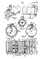
- the filter for purifying drinkable and non-drinkable water corn prises a body, which is generally designated with the reference numeral 1, which defines an inlet end 2 formed with an outer thread 3 for connection to swivel unions 4 or the like elements which allow the inlet end 2 to be connected to a water inlet.
- the cited inlet end is in communication, through a fitting 10, with a purifying filter, which advantageously comprises mutually assemblable segments comprising an end segment 11 having a bacteria hold-back membrane and one or more intermediate segments 12 forming an active carbon water passage zone.
- the filter body ha an axial conduit 15 which extends through all the segments and is in communication with the inlet fitting 10 for admitting into the purifying filter water entering the inlet end 2.
- the axial conduit 15 may be provided with perfo rated diaphragms thereon, as indicated at 16, which serve the function of creating a pressure drop to retard the water flow through the filter.
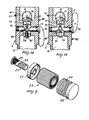
- the channel 15 which is defined by the individual portions in mutual sealed relationship formed in the various segments, is terminated at the end segment 11 which contains a front flange 21 whereto the axial conduit 15 is connected and is bored axial ly, and a bottom flange 22 which holds, in cooperation with the front flange 21, a pleated membrane 23 in a substantially cylindrical arrangement, which has the function of preventing bacteria from passing through.
- a containment net 24 which prevents the membrane from being deformed by excess pressure.
- a fine mesh filter 25 which is wrapped in an outer cloth layer 26 which, additionally to acting as a further filtering element, also creates a significant pressure drop.
- a containment net 27 which sur rounds the cloth layer 26 and encloses the element such as to prevent the membrane 23, in the event of sharp pressure variations, from being damaged.
- the active carbon segment is closed at its end by a filtering disk 32 which has the function of further reducing the pressure level and preventing the active carbons from exiting the cartridge.
- the felt filtering disk 32 is held pressed against a grid 33 positioned to close the purifying filter and being adapted to define an outlet chamber 35 wherein in practice the purified water through the filter is collected.
- the inlet end 2 is in communication with a diverter body 40, as well as with the filtering body as outlined hereinabove, which is rotatably associated with the filter body and defines on its interior a direct water dispensing conduit 41 and purified water dispensing conduit 42.
- the diverter body 40 also includes a purified water conduit 42, which also opens at the face adjacent the filter through a purified water inlet port, indicated at 45, which may be brought into alignment with a purified water discharge conduit 46 in communication with the purified water collecting chamber.
- the cited diverter body 40 may be positioned in to a first position whereat the inlet portion 44 is aligned to the port 43 and water entering the in let end 2, whereat a filtering body may be optional ly provided, is passed directly into the water dire ct delivery conduit and out, practically bypassing the filtering body.
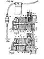
- the di verted body is turned, as shown in Figure 7, thereby the inlet portions 44 will be closed and the wa ter admitted into the inlet end 2 obliged to flow through the filter body and undergo purification through the segments 11 and 12 of the filter body.
- the purified water flows out of the conduit 46, which is aligned to the purified water discharge port 45, and is dispensed to the outside.
- position detents are provided which comprise small pegs 50 located at two diametrical locations on the filter body and being adapted to engage a detent 51 defined on the diverter body 40 by contact, thus provi ding two positions of utilization.
- the water admitted into the inlet end 2 is obliged to flow through the axial conduit 15 and whence into the segment 11 after going through a fine mesh filter, cloth, and contain ment net, then flows through the bacteria barrier membrane 23 which will hold back all the bacteria in suspension thus avoiding contamination of the ac tive carbon zone.
- the water After passing through the membrane 23, the water flows through the active carbons 31 with a very slow motion, that is, one effective to promote an intimate contact between the water and active carbons resulting in thorough purification of the water.
- the number of active carbon cartridges may be increased.
- a modular cartridge affords for the user the advantage of only replacing the worn cartridge portion, which generally comprises the active carbon portion, liable to be spent at a definitely higher rate than the segment carrying the antibacteria membrane.
- the water on leaving the active carbon zone, enters the outlet chamber 35, and hence, through the conduit 46, flows into the purified water delivery conduit 42, whence it is dispensed out.
- a vent conduit 60 which opens at the fitting portion 10 and extends out wards where a small vent valve is provided as indicated at 61.
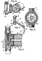
- the body in addition to the water inlet end or chamber 2, is provided also with a water delivery chamber 71, separated from the chamber 2 by a diaphragm 72.
- the diaphragm 72 is provided with an hole 73 whi ch is controlled by shutter means, generally denoted with 74, constituted by a stem 75 passing throu gh the hole 73 and provided with an enlarged head 76 which practically acts as a sealing member for the hole 73.
- shutter means generally denoted with 74, constituted by a stem 75 passing throu gh the hole 73 and provided with an enlarged head 76 which practically acts as a sealing member for the hole 73.
- the stem 75 is axially displaceable so that to be positioned in a first position, whereby the hole 73 is closed, and in a second position, whereby said stem allows the direct passage of water between the chamber 2 and the chamber 71.
- the stem is operated by means of a small shaft 77 diametrically supported in the chamber 71 and exten ding sealingly outwardly from the body 1 whereat a lever 78 is provided for its operation.
- the shaft 77 at a middle position thereof, has a tapering part 79 which is substantially offset with respect to rotation axis of the stem 77 and which engages with an opening 80 defined in the stem 75 and provided with a set screw 81 which engages with the tapering portion 79, so that rotation of the shaft 77 results, owing to the offsetting of the tapering portion 79, in an axial translation of the stem 75 and accordingly in the passage port 73 being uncovered or covered.
- position detents comprising small pegs 82 against which said lever abuts.
- the filter cartrid ge would be made without the movable diverter body, because all of the oncoming water would be previously purified.
- the deli very conduit may include a pumping element, indicated at 70, to promote suction and contribute to over come all the pressure losses and drops which origina te from within the filter body.
- the invention achieves its objects, and in particular, that the provision of a filtering membrane for holding back bacteria affords delivery of bacteriologically pure water and prevention of the active carbon contamination, while by passing the water to be purified first through the membrane and then through the active carbons, the carbon powder is prevented from rapidly clogging the membrane pores.
- Another aspect of the invention is that the construction of the drinkable water purifying filter according to the invention is greatly simplified, and hence of relatively lower manufacturing cost.
- the materials used if compatible with the intended application, and the dimensions and contingent shapes, may be any se lected ones to meet individual requirements.
Landscapes
- Engineering & Computer Science (AREA)
- Water Supply & Treatment (AREA)
- Chemical & Material Sciences (AREA)
- Life Sciences & Earth Sciences (AREA)
- Hydrology & Water Resources (AREA)
- Environmental & Geological Engineering (AREA)
- Organic Chemistry (AREA)
- Chemical Kinetics & Catalysis (AREA)
- Separation Using Semi-Permeable Membranes (AREA)
- Water Treatment By Sorption (AREA)
Priority Applications (1)
| Application Number | Priority Date | Filing Date | Title |
|---|---|---|---|
| AT84108412T ATE41912T1 (de) | 1983-07-28 | 1984-07-17 | Filter fuer die wasserreinigung. |
Applications Claiming Priority (4)
| Application Number | Priority Date | Filing Date | Title |
|---|---|---|---|
| IT2253583U IT8322535V0 (it) | 1983-07-28 | 1983-07-28 | Struttura di filtro per la purificazione di acqua potabile. |
| IT2253583U | 1983-07-28 | ||
| IT1969384 | 1984-02-17 | ||
| IT19693/84A IT1173300B (it) | 1984-02-17 | 1984-02-17 | Filtro per la purificazione di acqua potabile e non potabile |
Publications (3)
| Publication Number | Publication Date |
|---|---|
| EP0132762A2 true EP0132762A2 (de) | 1985-02-13 |
| EP0132762A3 EP0132762A3 (en) | 1985-12-11 |
| EP0132762B1 EP0132762B1 (de) | 1989-04-05 |
Family
ID=26327263
Family Applications (1)
| Application Number | Title | Priority Date | Filing Date |
|---|---|---|---|
| EP84108412A Expired EP0132762B1 (de) | 1983-07-28 | 1984-07-17 | Filter für die Wasserreinigung |
Country Status (5)
| Country | Link |
|---|---|
| US (1) | US4595500A (de) |
| EP (1) | EP0132762B1 (de) |
| DE (1) | DE3477562D1 (de) |
| ES (1) | ES8505828A1 (de) |
| GR (1) | GR82445B (de) |
Cited By (5)
| Publication number | Priority date | Publication date | Assignee | Title |
|---|---|---|---|---|
| FR2600908A1 (fr) * | 1986-07-02 | 1988-01-08 | Zellweger Uster Ag | Filtre pour appareils chimiques et utilisation du filtre dans un analyseur chimique automatique |
| FR2653424A1 (de) * | 1989-10-19 | 1991-04-26 | Skatron As | |
| AU644053B2 (en) * | 1991-06-28 | 1993-12-02 | Suntory Limited | Water purifier attachable to a faucet, and a holder and cartridge for use therein |
| EP0738532A3 (de) * | 1995-04-18 | 1996-10-30 | Eaton Corporation | Strömungsfilter für Ventil |
| KR20150138170A (ko) * | 2013-02-20 | 2015-12-09 | 헤래우스 크바르츠글라스 게엠베하 & 컴파니 케이지 | ArF 엑시머 레이저 리소그래피에서의 사용을 위한 석영 유리로 만들어진 광학 컴포넌트 및 그 컴포넌트를 제조하는 방법 |
Families Citing this family (19)
| Publication number | Priority date | Publication date | Assignee | Title |
|---|---|---|---|---|
| US4713175A (en) * | 1986-08-05 | 1987-12-15 | Nimbus Water Systems, Inc. | Water purifier comprising stages mounted side-by-side to unitary header |
| US4740296A (en) * | 1986-11-28 | 1988-04-26 | Roman Michael H | Household water filter system |
| FR2616773B1 (fr) * | 1987-06-19 | 1991-07-05 | Srti Soc Rech Tech Ind | Dispositif individuel portable de traitement d'eau |
| US5221473A (en) * | 1989-10-13 | 1993-06-22 | Burrows Bruce D | Filter cartridge assembly for a reverse osmosis purification system |
| US5037547A (en) * | 1989-10-13 | 1991-08-06 | Burrows Bruce D | Dual stage filter cartridge for a reverse osmosis purification system |
| US5314628A (en) * | 1992-09-14 | 1994-05-24 | Sloan Frank P | De-chlorinated water supply methods |
| US5376281A (en) * | 1993-07-21 | 1994-12-27 | Safta; Eugen | Water purification system |
| US5545315A (en) * | 1994-08-05 | 1996-08-13 | Wtc Industries, Inc. | Water filtering and purifying apparatus |
| US5744033A (en) * | 1996-12-06 | 1998-04-28 | Moen Incorporated | Water filter for use with a faucet |
| USD441834S1 (en) | 1999-06-29 | 2001-05-08 | Kimberly-Clark Worldwide, Inc. | Sink sprayer |
| US6368503B1 (en) | 1999-06-29 | 2002-04-09 | Kimberly-Clark Worldwide, Inc. | Filtered fluid dispensing system |
| US6818130B1 (en) * | 1999-09-30 | 2004-11-16 | Kimberly-Clark Worldwide, Inc. | Method and apparatus for multistage liquid filtration |
| US6457589B1 (en) | 2000-02-24 | 2002-10-01 | Kimberly-Clark Worldwide, Inc. | Fluid filtration and dispensing system |
| US6571960B2 (en) | 2000-05-01 | 2003-06-03 | Kimberly-Clark Worldwide, Inc. | Faucet-mounted water filtration device |
| US7081201B2 (en) * | 2002-04-19 | 2006-07-25 | 3M Innovative Properties Company | Encapsulated filter cartridge |
| US6989101B2 (en) | 2003-04-04 | 2006-01-24 | The Clorox Company | Microorganism-removing filter medium having high isoelectric material and low melt index binder |
| US7303683B2 (en) * | 2003-04-04 | 2007-12-04 | The Clorox Company | Microorganism-removing filter medium having high isoelectric material and low melt index binder |
| US20040206682A1 (en) * | 2003-04-18 | 2004-10-21 | Thomas Hamlin | Filter assembly utilizing carbon block and pleated filter element |
| US20100000931A1 (en) * | 2008-07-01 | 2010-01-07 | Janet Castillo | Potable liquid dispenser |
Family Cites Families (9)
| Publication number | Priority date | Publication date | Assignee | Title |
|---|---|---|---|---|
| US2335458A (en) * | 1943-03-29 | 1943-11-30 | Senyal Frank | Filter and water purifier |
| US3178025A (en) * | 1962-07-18 | 1965-04-13 | Gen Motors Corp | Dry cleaning filter with adsorbent means |
| US3327859A (en) * | 1963-12-30 | 1967-06-27 | Pall Corp | Portable unit for potable water |
| CA904756A (en) * | 1970-10-02 | 1972-07-11 | H. Klein Samuel | Filter system employing activated carbon, porous material and diatomaceous earth |
| US3802563A (en) * | 1970-12-23 | 1974-04-09 | Matsushita Electric Industrial Co Ltd | Water purifying device |
| US3951811A (en) * | 1974-06-27 | 1976-04-20 | Almag Pollution Control Corporation | Modular container |
| DE2535883A1 (de) * | 1975-08-12 | 1977-02-17 | Aquona Verwaltungsges | An einem wasserauslauf anbringbares kleingeraet zur wasseraufbereitung |
| FR2462187A1 (fr) * | 1979-07-26 | 1981-02-13 | Seb Sa | Purificateur d'eau portatif, notamment a usage domestique |
| US4379053A (en) * | 1981-06-12 | 1983-04-05 | Brane Earl P | Filter bypass valve assembly |
-
1984
- 1984-07-12 US US06/630,212 patent/US4595500A/en not_active Expired - Fee Related
- 1984-07-17 EP EP84108412A patent/EP0132762B1/de not_active Expired
- 1984-07-17 DE DE8484108412T patent/DE3477562D1/de not_active Expired
- 1984-07-18 ES ES534399A patent/ES8505828A1/es not_active Expired
- 1984-07-27 GR GR75440A patent/GR82445B/el unknown
Cited By (5)
| Publication number | Priority date | Publication date | Assignee | Title |
|---|---|---|---|---|
| FR2600908A1 (fr) * | 1986-07-02 | 1988-01-08 | Zellweger Uster Ag | Filtre pour appareils chimiques et utilisation du filtre dans un analyseur chimique automatique |
| FR2653424A1 (de) * | 1989-10-19 | 1991-04-26 | Skatron As | |
| AU644053B2 (en) * | 1991-06-28 | 1993-12-02 | Suntory Limited | Water purifier attachable to a faucet, and a holder and cartridge for use therein |
| EP0738532A3 (de) * | 1995-04-18 | 1996-10-30 | Eaton Corporation | Strömungsfilter für Ventil |
| KR20150138170A (ko) * | 2013-02-20 | 2015-12-09 | 헤래우스 크바르츠글라스 게엠베하 & 컴파니 케이지 | ArF 엑시머 레이저 리소그래피에서의 사용을 위한 석영 유리로 만들어진 광학 컴포넌트 및 그 컴포넌트를 제조하는 방법 |
Also Published As
| Publication number | Publication date |
|---|---|
| DE3477562D1 (en) | 1989-05-11 |
| GR82445B (de) | 1984-12-13 |
| ES534399A0 (es) | 1985-07-01 |
| ES8505828A1 (es) | 1985-07-01 |
| EP0132762B1 (de) | 1989-04-05 |
| US4595500A (en) | 1986-06-17 |
| EP0132762A3 (en) | 1985-12-11 |
Similar Documents
| Publication | Publication Date | Title |
|---|---|---|
| US4595500A (en) | Filter for purifying drinkable and non-drinkable water | |
| US5221473A (en) | Filter cartridge assembly for a reverse osmosis purification system | |
| US4556484A (en) | Water filters | |
| US3370708A (en) | Dual element, dual valve, twist-on type filter assembly | |
| US6258266B1 (en) | Faucet mount water filtration device | |
| US3529722A (en) | Combined anti-drain back valve and by-pass valve | |
| CN107899279A (zh) | 滤芯组件和净水系统 | |
| CN218058627U (zh) | Ro逆流膜复合滤芯结构 | |
| CN209872549U (zh) | 一种四合一复合滤芯及其净水器 | |
| CN111151138A (zh) | 侧进水的过滤组件及应用其的滤芯结构 | |
| JP2008207175A (ja) | 浄水器 | |
| GB1069900A (en) | Apparatus for controlling fluid flow through filtering screens | |
| CN208603866U (zh) | 一种可拆卸式反渗透复合滤芯组件 | |
| US4740296A (en) | Household water filter system | |
| CN212819174U (zh) | 侧进水的新型过滤组件 | |
| US4587017A (en) | Filter incorporating multiple chambers for receiving the filtered fluid and another fluid issuing from the residue of the main filtration | |
| CN109912059A (zh) | 一种反渗透复合滤芯组件 | |
| GB2257052A (en) | Water purifier attachable to a faucet | |
| CN211394110U (zh) | 一种可拆卸复合滤芯 | |
| CN111875000A (zh) | 反渗透滤芯及净水器 | |
| US3984325A (en) | Filter device | |
| CN110040860A (zh) | 反渗透复合滤芯组件 | |
| CN115477401B (zh) | 滤芯及其装配方法、净水装置 | |
| CN212246335U (zh) | 反渗透滤芯及净水器 | |
| CN213433247U (zh) | 一种滤芯结构和净水装置 |
Legal Events
| Date | Code | Title | Description |
|---|---|---|---|
| PUAI | Public reference made under article 153(3) epc to a published international application that has entered the european phase |
Free format text: ORIGINAL CODE: 0009012 |
|
| AK | Designated contracting states |
Designated state(s): AT BE CH DE FR GB IT LI LU NL SE |
|
| PUAL | Search report despatched |
Free format text: ORIGINAL CODE: 0009013 |
|
| AK | Designated contracting states |
Designated state(s): AT BE CH DE FR GB IT LI LU NL SE |
|
| 17P | Request for examination filed |
Effective date: 19860521 |
|
| 17Q | First examination report despatched |
Effective date: 19870622 |
|
| GRAA | (expected) grant |
Free format text: ORIGINAL CODE: 0009210 |
|
| AK | Designated contracting states |
Kind code of ref document: B1 Designated state(s): AT BE CH DE FR GB IT LI LU NL SE |
|
| PG25 | Lapsed in a contracting state [announced via postgrant information from national office to epo] |
Ref country code: SE Effective date: 19890405 Ref country code: NL Effective date: 19890405 Ref country code: LI Effective date: 19890405 Ref country code: CH Effective date: 19890405 Ref country code: BE Effective date: 19890405 Ref country code: AT Effective date: 19890405 |
|
| REF | Corresponds to: |
Ref document number: 41912 Country of ref document: AT Date of ref document: 19890415 Kind code of ref document: T |
|
| REF | Corresponds to: |
Ref document number: 3477562 Country of ref document: DE Date of ref document: 19890511 |
|
| ITF | It: translation for a ep patent filed | ||
| REG | Reference to a national code |
Ref country code: CH Ref legal event code: PL |
|
| PG25 | Lapsed in a contracting state [announced via postgrant information from national office to epo] |
Ref country code: LU Free format text: LAPSE BECAUSE OF NON-PAYMENT OF DUE FEES Effective date: 19890731 |
|
| ET | Fr: translation filed | ||
| NLV1 | Nl: lapsed or annulled due to failure to fulfill the requirements of art. 29p and 29m of the patents act | ||
| PLBE | No opposition filed within time limit |
Free format text: ORIGINAL CODE: 0009261 |
|
| STAA | Information on the status of an ep patent application or granted ep patent |
Free format text: STATUS: NO OPPOSITION FILED WITHIN TIME LIMIT |
|
| 26N | No opposition filed | ||
| PGFP | Annual fee paid to national office [announced via postgrant information from national office to epo] |
Ref country code: FR Payment date: 19900619 Year of fee payment: 7 |
|
| PGFP | Annual fee paid to national office [announced via postgrant information from national office to epo] |
Ref country code: GB Payment date: 19900716 Year of fee payment: 7 |
|
| PGFP | Annual fee paid to national office [announced via postgrant information from national office to epo] |
Ref country code: DE Payment date: 19900906 Year of fee payment: 7 |
|
| PG25 | Lapsed in a contracting state [announced via postgrant information from national office to epo] |
Ref country code: GB Effective date: 19910717 |
|
| ITTA | It: last paid annual fee | ||
| GBPC | Gb: european patent ceased through non-payment of renewal fee | ||
| PG25 | Lapsed in a contracting state [announced via postgrant information from national office to epo] |
Ref country code: FR Effective date: 19920331 |
|
| PG25 | Lapsed in a contracting state [announced via postgrant information from national office to epo] |
Ref country code: DE Effective date: 19920401 |
|
| REG | Reference to a national code |
Ref country code: FR Ref legal event code: ST |