EP0132767A2 - Tête de préhension munie de deux doigts déplaçables l'un vers l'autre - Google Patents
Tête de préhension munie de deux doigts déplaçables l'un vers l'autre Download PDFInfo
- Publication number
- EP0132767A2 EP0132767A2 EP84108434A EP84108434A EP0132767A2 EP 0132767 A2 EP0132767 A2 EP 0132767A2 EP 84108434 A EP84108434 A EP 84108434A EP 84108434 A EP84108434 A EP 84108434A EP 0132767 A2 EP0132767 A2 EP 0132767A2
- Authority
- EP
- European Patent Office
- Prior art keywords
- gripping members
- gripping
- fingers
- gripper
- gripper according
- Prior art date
- Legal status (The legal status is an assumption and is not a legal conclusion. Google has not performed a legal analysis and makes no representation as to the accuracy of the status listed.)
- Withdrawn
Links
Images


Classifications
-
- B—PERFORMING OPERATIONS; TRANSPORTING
- B25—HAND TOOLS; PORTABLE POWER-DRIVEN TOOLS; MANIPULATORS
- B25J—MANIPULATORS; CHAMBERS PROVIDED WITH MANIPULATION DEVICES
- B25J15/00—Gripping heads and other end effectors
- B25J15/08—Gripping heads and other end effectors having finger members
- B25J15/10—Gripping heads and other end effectors having finger members with three or more finger members
- B25J15/106—Gripping heads and other end effectors having finger members with three or more finger members moving in parallel relationship
Definitions
- the invention relates to a gripper with two fingers movable relative to one another.
- Such grippers are used, for example, for industrial robots to handle various types of objects.
- two pliers-shaped, rigid fingers are provided, which grip and clamp the object from opposite sides. So that the object is securely held on the one hand between the fingers and on the other hand is not damaged during clamping, the shape of the fingers usually has to be adapted in a special way to the shape of the object.
- a particular gripper can therefore only be used for a narrowly limited class of objects. Although this disadvantage can be alleviated by the fact that the gripper surfaces of the fingers are padded with elastic material, this also does not lead to satisfactory results in the case of objects with a very different shape.
- the invention has for its object to provide a gripper of the type mentioned, which automatically adapts to the respective outer contour of the object to be gripped.
- At least one finger of the gripper comprises a number of gripping members which are movable relative to one another and which can be pressed against an object to be gripped with the aid of separate but interconnected hydraulic cylinders.
- the mutually movable gripping members on the one hand offer the possibility of adapting to the outer contour of the object, but on the other hand are all under the same pressure due to their hydraulic connection, so that the contact forces of the gripping members are evenly distributed over the entire surface of the object and damage by one strong local forces are avoided.
- the hydraulic connection can exist either for the gripping members of one finger or for the gripping members of both fingers, so that there is complete pressure compensation.
- these can either be formed by two mutually opposite groups of gripping members, which are arranged on a common holder, or by a divided holder, which forms two mutually movable jaws on which a group of gripping members is arranged in each case.
- the gripping members can be linearly displaceable lamellae or pins or swiveling gripping members of any shape.
- the hydraulic system serving to drive the gripping members preferably comprises a number of bores in the holder tion or the jaws in which pistons slide, which act in a suitable manner on the gripping members. These can be returned to the rest position by springs.
- the gripping movement of the gripping members can be in the closing direction, but possibly also in the spreading direction if, for example, a pot-shaped object is to be gripped from the inside.
- two pistons act on each gripping member in the opposite direction of movement, so that the gripping process can alternatively take place in the closing or opening direction.
- At least one gripping member from a group of gripping members can be synchronized with a corresponding gripping member of the second group, so that the opening and closing movement takes place symmetrically. In this way, the detected object arrives exactly in the middle position, so that, for example, it can be set down in a predetermined position.
- the remaining gripping members can freely adapt to the shape of the object in the manner described above.
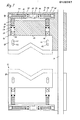
- a gripper shown in FIGS. 1 and 2 comprises two identically constructed jaws 10, 12, which can be moved along guide rods 14 with the aid of a drive (not shown).
- the jaws 10, 12 each have a rectangular recess 16 in their mutually facing surfaces, which accommodates a set of lamellae 18 lying flat against one another.
- the slats 18 are each V-shaped on their edge facing the other cheek and form gripping members for gripping an object, not shown, located between the two sets of slats.
- Each of the lamellae 18 has two elongated holes 20, which each receive a rod 22 fastened to the jaw 10 or 12 and running across all the lamellae, and can thus be displaced with respect to the jaw in a limited area parallel to the guide rods 14.
- Fig. 1 the slats are shown in their fully retracted position in the jaws, while the fully extended position of the slats is indicated by dashed lines.
- Each of the lamellae has on its inner edge 24 facing the jaw two projections 26 arranged in the extension of the elongated holes 20, which protrude into cylindrical bores 28 of the jaw 10, 12.
- Each of the bores 28 receives a piston 32 provided with a sealing ring 30, which is biased towards the extension 26 by a spring 34 with a low spring constant.
- the sections of the bores 28 which receive the springs 34 are connected to one another by a chamber 36.
- the chamber 36 is connected via a tap hole 38 to a buffer chamber 42 delimited by two pistons 40.
- the pistons 40 are biased in the direction of the buffer chamber 42 by two springs 44, 46 with different spring constants.
- the springs 44, 46 are each supported on a plug 48 at the outer ends.
- the bore forming the buffer chamber 42 and receiving the pistons 40, the springs 44, 46 and the plugs 48 is formed in a block 50 which is detachable from the main body of the jaw 10, 12, so that the springs 34, 44, 46 after removal of the block 50 and the plug 48 replaced or by. the plugs can be tightened deeper.
- the block 50 is sealingly connected to the main body of the jaw, so that the Buffer chamber 42, the tap hole 38, the chamber 36 and the bores 28 form a closed cavity.
- This cavity is completely filled with a working fluid, for example a brake fluid.
- the jaws 10, 12 are moved towards one another.
- the jaws are moved, for example, with a drive, the driving force of which can be limited to a value at which there is no risk of damage to the object.
- the slats 18 are held by the springs 34 in the extended position shown in dashed lines in FIG. 1.
- the first fins strike the object, they are pushed back into the recess 16, and the pistons 32 assigned to these fins are pushed further into the bores 28 by the lugs 26.
- the springs 34 provide little resistance to this movement.
- the reduction in volume caused by the inward movement of the pistons is compensated for by compression of the likewise easily compressible spring 44 while displacing one of the pistons 40. If, during the further movement of the jaws 10, 12, the other lamellae 18 also gradually hit the object and, depending on the shape of the object, are pushed more or less far into the recess 16, the total volume of the bores 28 is reduced so much, that the spring 44 is fully compressed. As the jaws 10, 12 move further, the compression of the stronger spring 46 begins, and the fluid pressure in the hydraulic systems of the two jaws - and thus the resistance to the movement of the jaws 10, 12 - increases noticeably. If this resistance exceeds a predetermined threshold, the jaw drive is switched off, and the object is firmly and securely clamped between the plate sets.
- the lugs 26 of the lamellae have a rectangular cross section, while the bores 28 have a circular cross section.
- the bores 28 are staggered in several parallel rows.
- the lamellae 18 can be arranged directly next to one another, although their width is less than the diameter of the bores 28.
- the pistons 32 assigned to the same lamellae 18 have corresponding active surfaces, so that the hydraulic forces acting on them are the same and the slat is not tilted.
- the pistons 32 belonging to different fins can also have different active surfaces, so that the fins are pressed onto the object with different contact pressure.
- Different contact forces can also be achieved in that the bores assigned to a lamella are connected to one another by a channel instead of through the chamber 26 and are separated from the other bores 28 and that a separate buffer unit corresponding to the block 50 is provided for each pair of bores Springs 44,46 of different strength is provided.
- a buffer such as is formed by the buffer chamber 42, the pistons 40 and the springs 44, 46, has the advantage that the object can be gripped particularly softly and gently.
- a similar buffering effect can optionally also be included in the hydraulic systems Air bubbles can be achieved.
- the buffer can also be completely omitted, so that the H y drauliksystem comprises only the chamber 26 and the bores 28th
- the volume of the working fluid must be selected such that the slats 18 in the rest position take up a middle position between the extreme positions shown in FIG. 1, so that the volume reduction which occurs during the inward movement of a part of the slats due to an outward movement of the other slats can be compensated.
- the volume of the buffer chamber 42 can be changed with the aid of a piston which can be actuated from the outside or a screw-in spindle, so that the hydraulic pressure and thus the clamping force can be varied as required.
- the jaws do not have to be arranged so that they can be moved in parallel on guide rods. Rather, they can also be located on the tongues of a gripping pliers, which may also be a multi-joint pliers with a toggle mechanism.
- the available space will generally be an important consideration for the selection.
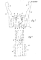
- FIGS. 3 and 4 While in the previously described embodiment the gripping members are arranged on two mutually movable jaws and are in turn movable with respect to the jaws, an embodiment will be described below with reference to FIGS. 3 and 4, in which two groups of gripping members against one another and with respect to one common bracket are movable.
- a holder 52 has, according to FIGS. 3 and 4, the shape of a cuboid block, on which two plates 54, 56 are fastened on two opposite sides, which in the example shown in FIG. 3 protrude the block 52 to the right and left and upwards .
- the plate 54 facing the viewer has been omitted for clarity.
- gripping members 58, 60, 62, 64 and 66 are mounted on both sides of the block 52. This storage takes place with the aid of axes 68, 70 which pivotally accommodate the gripping members and connect the plates 54, 56 to one another. It can be seen from FIG. 4 that the gripping members 58, 60, 62, 64 lie directly against one another in the lower region lying between the plates 54, 56, but are formed narrower in the upper region and have mutual distances.
- the gripping members 58, 60, 62, 64, 66 overall have the shape of narrow, flat strips. They are provided in the area of their free ends on the mutually facing sides with notches 72, 74 for grasping an object. In the lower area in FIG. 3, the gripping members have a chamfer, which is not described in any more detail, which leads to the gripping members assuming a slightly spread position when they bear against the block 52. In this position, the gripping members are prestressed by compression springs 76, 78, which are located in blind bores 80, 82 on the top of the block 52 and, on the other hand, support on lugs 84, 86 which extend inwards from the gripping members, that is to say in the direction of the respective other gripping member group.
- FIG. 3 the hydraulic drive of the gripping members is indicated in dashed lines in FIG. 3, which here also essentially corresponds to the principle described in connection with the first embodiment, but is designed differently in detail in terms of construction.
- a continuous bore 88 serving as a cylinder is provided between two opposite gripping members, in the example of FIG. 3 between gripping members 58 and 66, in which two pistons 90, 92 lie, the total length of which corresponds to that of the bore.
- the pistons have a truncated cone-shaped bevel 94.96 at the mutually abutting end.
- annular chamber In the area of the bevels 94, 96, an annular chamber, not shown, is formed in the bore 88, into which a branch channel 98 opens, which emanates from a common main channel 100, through which all the bores of the pairs of gripper members are supplied with hydraulic fluid will.
- the gripping process can also consist in a spreading movement in which, for example, a grip is made into the interior of a pot-shaped object.
- embodiments are considered that are double-acting and allow both gripping movements, as will be explained below using the example of FIGS. 5 to 7.
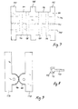
- FIG. 5 again shows a block 102, on which in this case four pairs of opposing gripping members are mounted, of which only the gripping members 104, 106 are shown in FIG. 5.
- the block 102 comprises a central and two outer, rectangular carrier plates 108, 110, 112, between the upper and lower edges of which cylinder plates 114, 116, 118, 120 are fastened, which, according to FIG. 6, form two essentially rectangular recesses 122, 124 together with the carrier plates.
- cylinder plates 114, 116, 118, 120 there are two bores 126, 128, 130, 132, 134, 136, 138, 140 which run perpendicular to the plane of the drawing in FIG. 6 and serve as cylinders of the hydraulic drive according to the invention.
- the carrier plate 112 is omitted in FIG. 5.
- axes 150, 152 are in Figure 5 shown.
- the gripping members 104, 106 have essentially semicircular projections 154, 156 on the sides facing one another, through which the axes 150, 152 pass.
- the gripping members 104, 106 shown in FIG. 5 serve only as carriers for the gripping fingers (not shown) or other gripping mechanisms which can be brought together or even spread during gripping. Bores 166, 168 are indicated for fastening such mechanisms.
- the pistons 158, 160, 162, 164 can act directly on the inner surfaces of the gripping members 104, 106, but in view of the pivoting movement carried out by the gripping members, this can lead to eccentric loads on the pistons and thus to signs of wear. Screws 170 according to FIG. 8 can therefore be screwed into the gripping members 104, 106, which have a spherical head 172 and a movable cap 174 placed thereon, each of which is in its position the face of the piston.
- FIG. 9 shows, using the example of a pair of gripping members 176, 178, one possibility for supplementing a gripper according to the invention, which can basically be used for all the described embodiments.
- the gripping members 176, 178 which correspond to the gripping members 104, 106 according to FIG. 5, have intermeshing teeth on the mutually facing, semicircular projections 180, 182, which lead to a synchronization of the movement of the gripping members.
- Such a pair of gripping members can be used if an object is to be brought into a predetermined, centered position when being gripped.
- this synchronization should only be used for individual pairs of grippers, such as the two outer pairs of grippers, so that the other pairs of grippers remain freely movable and can adapt to the shape of the gripped object.
Landscapes
- Engineering & Computer Science (AREA)
- Robotics (AREA)
- Mechanical Engineering (AREA)
- Manipulator (AREA)
Applications Claiming Priority (2)
| Application Number | Priority Date | Filing Date | Title |
|---|---|---|---|
| DE3327060 | 1983-07-27 | ||
| DE19833327060 DE3327060A1 (de) | 1983-07-27 | 1983-07-27 | Greifer mit zwei gegeneinander beweglichen backen |
Publications (2)
| Publication Number | Publication Date |
|---|---|
| EP0132767A2 true EP0132767A2 (fr) | 1985-02-13 |
| EP0132767A3 EP0132767A3 (fr) | 1986-04-02 |
Family
ID=6205045
Family Applications (1)
| Application Number | Title | Priority Date | Filing Date |
|---|---|---|---|
| EP84108434A Withdrawn EP0132767A3 (fr) | 1983-07-27 | 1984-07-17 | Tête de préhension munie de deux doigts déplaçables l'un vers l'autre |
Country Status (2)
| Country | Link |
|---|---|
| EP (1) | EP0132767A3 (fr) |
| DE (1) | DE3327060A1 (fr) |
Cited By (1)
| Publication number | Priority date | Publication date | Assignee | Title |
|---|---|---|---|---|
| BE1019328A3 (fr) * | 2009-05-14 | 2012-06-05 | Zahoransky Ag | Pince de prehension. |
Families Citing this family (5)
| Publication number | Priority date | Publication date | Assignee | Title |
|---|---|---|---|---|
| EP0638396B1 (fr) * | 1989-12-19 | 1998-03-11 | Amada Company Limited | Dispositif de connection rapide pour tête outil de manipulateur |
| DE4339102A1 (de) * | 1992-11-26 | 1994-06-01 | Friedhelm Prof Dipl Ing Sehrt | Handhabungsvorrichtung zum mechanischen Greifen, Halten, Bewegen oder dergl. Handhaben von Gegenständen insbesondere für Handhabungsgeräte |
| DE19531927C2 (de) * | 1995-08-16 | 1998-09-17 | Mannesmann Ag | Vorrichtung zum Greifen und Transportieren von Stückgut, insbesondere von Behältern |
| US5718531A (en) * | 1996-01-22 | 1998-02-17 | Lockheed Martin Corporation | Low shock release device |
| JP2989557B2 (ja) * | 1996-12-06 | 1999-12-13 | 株式会社椿本チエイン | 物品把持装置 |
Family Cites Families (5)
| Publication number | Priority date | Publication date | Assignee | Title |
|---|---|---|---|---|
| SU210348A (fr) * | ||||
| GB1332796A (en) * | 1970-08-24 | 1973-10-03 | Unigrip Mfg Co Ltd | Work piece supporting a holding device |
| JPS51126668A (en) * | 1975-04-25 | 1976-11-04 | Anritsu Corp | Robot handling means |
| DE2823584C2 (de) * | 1978-05-30 | 1983-01-27 | Pfaff Industriemaschinen Gmbh, 6750 Kaiserslautern | Greifvorrichtung für Industrieroboter |
| GB2049616B (en) * | 1979-05-22 | 1982-12-22 | Marconi Co Ltd | Manipulator mechanisms |
-
1983
- 1983-07-27 DE DE19833327060 patent/DE3327060A1/de not_active Withdrawn
-
1984
- 1984-07-17 EP EP84108434A patent/EP0132767A3/fr not_active Withdrawn
Cited By (1)
| Publication number | Priority date | Publication date | Assignee | Title |
|---|---|---|---|---|
| BE1019328A3 (fr) * | 2009-05-14 | 2012-06-05 | Zahoransky Ag | Pince de prehension. |
Also Published As
| Publication number | Publication date |
|---|---|
| DE3327060A1 (de) | 1985-02-07 |
| EP0132767A3 (fr) | 1986-04-02 |
Similar Documents
| Publication | Publication Date | Title |
|---|---|---|
| EP0468335B1 (fr) | Outil pour le sertissage d'un connecteur à un conducteur et une isolation | |
| DE102019100898A1 (de) | Spannvorrichtung für ein hülsenförmiges Werkstück, und Handhabungsvorrichtung, eine solche Spannvorrichtung umfassend | |
| DE3049282C2 (fr) | ||
| EP1103498A1 (fr) | Dispositif pour saisir des charges, qui en particulier sont saisi par le haut ou latéralement au moyen d' un manipulateur | |
| DE2801249C2 (de) | Entgratungsvorrichtung in einer auf einem zu entgratenden Schienenstrang geführten Stumpfschweißmaschine | |
| DE19817882A1 (de) | Radialpresse | |
| DE2535817C3 (de) | Klemmeinrichtung an einer Revolverstanze | |
| DE3436075C1 (de) | Vorrichtung zur Ioesbaren Verbindung von Greiferschienenteilen der Greiferschienen in einer Transfer-Presse | |
| DE3605099A1 (de) | Vorrichtung zum auswechseln der elektrodenkappen einer roboter-punktschweisszange | |
| CH621959A5 (fr) | ||
| EP0132767A2 (fr) | Tête de préhension munie de deux doigts déplaçables l'un vers l'autre | |
| DE2157274A1 (de) | Vorrichtung zum Verformen bzw. Verpressen | |
| EP1238730B1 (fr) | Mandrin de serrage | |
| EP2522464B1 (fr) | Mordache et procédé de fabrication d'un emmanchement par pressage | |
| DE3502575A1 (de) | Kurzhub-spannelement | |
| AT515407B1 (de) | Biegewerkzeug sowie Wechseleinheit hierfür | |
| DE102021211275B4 (de) | Greifvorrichtung mit Kulissengetriebe und Hebelgetriebe | |
| EP0143257A1 (fr) | Raccordement d'outil d'une presse de découpage, notamment d'une presse de découpage à plateau revolver, pour le changement d'outil | |
| DE29918229U1 (de) | Probenhalter zum Spannen von Werkstücken | |
| EP0266625B1 (fr) | Support d'outil supérieur pour un poinçon ou un élément similaire | |
| DE2631119C3 (de) | Gummituchspannvorrichtung | |
| DE3783003T2 (de) | Verfahren und vorrichtung zum entbeinen von fleischteilen. | |
| DE2443376C2 (de) | Pneumatisch oder hydraulisch betätigbare Rahmenpresse | |
| DE60114695T2 (de) | Wringvorrichtung und Folgewerkzeug mit solcher Vorrichtung | |
| DE7716592U1 (de) | Faltverschluss fuer elastische Folien insbesondere Kunststoff-Folien |
Legal Events
| Date | Code | Title | Description |
|---|---|---|---|
| PUAI | Public reference made under article 153(3) epc to a published international application that has entered the european phase |
Free format text: ORIGINAL CODE: 0009012 |
|
| AK | Designated contracting states |
Designated state(s): AT BE CH DE FR GB IT LI LU NL SE |
|
| PUAL | Search report despatched |
Free format text: ORIGINAL CODE: 0009013 |
|
| AK | Designated contracting states |
Kind code of ref document: A3 Designated state(s): AT BE CH DE FR GB IT LI LU NL SE |
|
| 17P | Request for examination filed |
Effective date: 19861202 |
|
| 17Q | First examination report despatched |
Effective date: 19880118 |
|
| STAA | Information on the status of an ep patent application or granted ep patent |
Free format text: STATUS: THE APPLICATION IS DEEMED TO BE WITHDRAWN |
|
| 18D | Application deemed to be withdrawn |
Effective date: 19890410 |