EP0132778A2 - Kombinationsschloss des Typs mit Zuhaltungsscheiben - Google Patents
Kombinationsschloss des Typs mit Zuhaltungsscheiben Download PDFInfo
- Publication number
- EP0132778A2 EP0132778A2 EP84108473A EP84108473A EP0132778A2 EP 0132778 A2 EP0132778 A2 EP 0132778A2 EP 84108473 A EP84108473 A EP 84108473A EP 84108473 A EP84108473 A EP 84108473A EP 0132778 A2 EP0132778 A2 EP 0132778A2
- Authority
- EP
- European Patent Office
- Prior art keywords
- stud
- seats
- drive
- dials
- driver element
- Prior art date
- Legal status (The legal status is an assumption and is not a legal conclusion. Google has not performed a legal analysis and makes no representation as to the accuracy of the status listed.)
- Granted
Links
Images



Classifications
-
- E—FIXED CONSTRUCTIONS
- E05—LOCKS; KEYS; WINDOW OR DOOR FITTINGS; SAFES
- E05B—LOCKS; ACCESSORIES THEREFOR; HANDCUFFS
- E05B37/00—Permutation or combination locks; Puzzle locks
- E05B37/08—Permutation or combination locks; Puzzle locks with tumbler discs on a single axis, all the discs being adjustable by a rotary knob which is not shifted for adjusting the discs
-
- Y—GENERAL TAGGING OF NEW TECHNOLOGICAL DEVELOPMENTS; GENERAL TAGGING OF CROSS-SECTIONAL TECHNOLOGIES SPANNING OVER SEVERAL SECTIONS OF THE IPC; TECHNICAL SUBJECTS COVERED BY FORMER USPC CROSS-REFERENCE ART COLLECTIONS [XRACs] AND DIGESTS
- Y10—TECHNICAL SUBJECTS COVERED BY FORMER USPC
- Y10T—TECHNICAL SUBJECTS COVERED BY FORMER US CLASSIFICATION
- Y10T70/00—Locks
- Y10T70/70—Operating mechanism
- Y10T70/7153—Combination
- Y10T70/7181—Tumbler type
- Y10T70/7198—Single tumbler set
- Y10T70/7237—Rotary or swinging tumblers
- Y10T70/7243—Interset tumblers
- Y10T70/7249—Tumblers released
- Y10T70/7254—Fence held spaced from tumblers
-
- Y—GENERAL TAGGING OF NEW TECHNOLOGICAL DEVELOPMENTS; GENERAL TAGGING OF CROSS-SECTIONAL TECHNOLOGIES SPANNING OVER SEVERAL SECTIONS OF THE IPC; TECHNICAL SUBJECTS COVERED BY FORMER USPC CROSS-REFERENCE ART COLLECTIONS [XRACs] AND DIGESTS
- Y10—TECHNICAL SUBJECTS COVERED BY FORMER USPC
- Y10T—TECHNICAL SUBJECTS COVERED BY FORMER US CLASSIFICATION
- Y10T70/00—Locks
- Y10T70/70—Operating mechanism
- Y10T70/7153—Combination
- Y10T70/7322—Permutation
- Y10T70/7328—Compound tumblers
-
- Y—GENERAL TAGGING OF NEW TECHNOLOGICAL DEVELOPMENTS; GENERAL TAGGING OF CROSS-SECTIONAL TECHNOLOGIES SPANNING OVER SEVERAL SECTIONS OF THE IPC; TECHNICAL SUBJECTS COVERED BY FORMER USPC CROSS-REFERENCE ART COLLECTIONS [XRACs] AND DIGESTS
- Y10—TECHNICAL SUBJECTS COVERED BY FORMER USPC
- Y10T—TECHNICAL SUBJECTS COVERED BY FORMER US CLASSIFICATION
- Y10T70/00—Locks
- Y10T70/70—Operating mechanism
- Y10T70/7153—Combination
- Y10T70/735—Operating elements
- Y10T70/7356—Fences
-
- Y—GENERAL TAGGING OF NEW TECHNOLOGICAL DEVELOPMENTS; GENERAL TAGGING OF CROSS-SECTIONAL TECHNOLOGIES SPANNING OVER SEVERAL SECTIONS OF THE IPC; TECHNICAL SUBJECTS COVERED BY FORMER USPC CROSS-REFERENCE ART COLLECTIONS [XRACs] AND DIGESTS
- Y10—TECHNICAL SUBJECTS COVERED BY FORMER USPC
- Y10T—TECHNICAL SUBJECTS COVERED BY FORMER US CLASSIFICATION
- Y10T70/00—Locks
- Y10T70/70—Operating mechanism
- Y10T70/7153—Combination
- Y10T70/735—Operating elements
- Y10T70/7367—Tumbler structure and position
Definitions
- This invention relates to a dial-type combination lock.
- combination locks which comprise, as the basic components thereof, combination dials or disks formed with edge seats or “gates”, a driver element operable from the outside, e.g. through an indexed knob, and arranged to act on said dials and provided with a drive seat located at its periphery, and a stud mounted on a bolt element of the lock.
- Said stud is adapted to engage with all of said seats when the latter are brought into mutual alignment, that is, when the driver element, operatively connected to said dials, is turned from the outside into a set combination.
- the stud with a barb-like shape having a hooked end which can be inserted into the drive seat of the driver element and the opposite end articulated, through a swivel connection, on said bolt element.
- This prior stud configuration is further provided with a lug adapted for insertion into said edge seats on the combination dials. When the latter have their respective edge seats aligned to one another, said lug moves into the seats and the stud is allowed to rotate about said swivel connection and engage with the driver element through its hooked end.
- the driver element is made operatively rigid with the bolt element and can move it to open a door or the like.
- the combination dials are currently formed by rings engaging, by means of specially provided internal grippers, with peripherally toothed hubs.
- the rings are formed peripherally with the cited “gates" or edge seats, the hubs having guide projections adapted to operatively connect each combination dial to adjacent dials and said driver element.
- the angular offset of the edge seats from the guide projections determines the combination numbers to be set in order to align said edge seats and enable said stud to "hook up" said driver element to connect it to said bolt element.
- the barbed stud enters said edge seats or "gates" along a path on an arc of a circle with its pivot point on said swivel connection.
- This path form requires that considerable play be allowed between the stud and edge seats, and this play permits the lock to be opened even with different combinations from the set one, so long as they happen to be proximate to it.
- a dial-type combination lock comprising, on a stationary supporting frame, a bolt element connected to external closure elements controlled by the lock itself, a driver element manually turnable from the outside and having a drive seat at one edge thereof, a plurality of rotatable coaxial combination dials operatively connected together and to said driver element, as well as having edge seats adapted to be moved into mutual alignment relationship, and a stud engageable with said seats and adapted to transmit the movements of said driver element to said bolt element, said stud being movable from a released position to a working position whereat said stud engages with all of said seats, characterized in that said stud includes a base portion extending parallel to said dials and arranged to be rotatable coaxially therewith, and hooking members adapted for insertion in said seats and projecting from said base portion in a transverse direction to the plane of lay thereof, and in that guide elements are provided in said stationary frame operative to impart to said hooking members linear oscillations in a radial direction to said
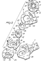
- a combination lock is generally designated with the reference numeral 1 in Figure 1, where it is shown in sehematic form. It comprises, as illustrated, a supporting frame 2 defined by a number of spacers or posts 3, a pair of end plates 4 which may be part of a door or the like to be locked by means of the lock 1, and a fixed plate 5 which separates that portion of the lock 1 where the combination dials or disks 6 are mounted from that portion of the lock which carries control members for the combination dials 6 and a bolt element 7.
- a tube 8 Located centrally to the lock 1, is a tube 8 lying coaxially with the combination dials 6 and serving the function of a central support for the various lock members. Inserted into the tube 8 is a control rod 9 connected to an indexed knob or knob with pointer, while on the exterior of the tube 8, there engages rotatably a driver element 10 which is box fitted to the control rod 9 and operates the lock as a whole. In particular t the driver element 10 is at all times keyed, through a drive pin 11, to the combination dials 6, which it drives rotatively. More detailedly, the driver element 10 has the contour shown in Figure 2 and includes a hollow cylindrical portion 10a and ring-like portion 10b.
- the latter has on its exterior a shaped annular rim 12 defined substantially by a cylindrical band having a drive seat 13 formed therein the edges whereof are, the one bevelled with a sloping surface and the other straight stepped.
- the straight edge is the active or thrust edge as the driver element 10 is rotated in a clockwise direction by the control rod 9.
- a stud 14 Coaxially with the cylindrical portion 10a of the driver element 10, on the exterior thereof, there is mounted a stud 14 which comprises a sheet-like base portion 15, and members for engagement with the drive seat 13 and edge seats 17 formed in the combination dials 6.
- the base portion 15 extends parallel to the combination dials 6, and is formed at its center with a guide hole 15a adapted to permit the stud 14 to oscillate linearly and parallely to the base portion 15.
- the cited engagement, or hooking, members include a first drive lug 18a projecting perpendicularly from the base portion 15 and adapted for insertion into the drive seat 13, and an interlock rod 19 mainly extending in a parallel direction to the first drive lug 18a and being intended for insertion into the edge seats 17, as shows Figure 1.
- the distance from the first drive lug 18a to the interlock rod 19 is such that, as the first drive lug 18a is brought to bear on the shaped annular rim 12, out of the drive seat 13, the interlock rod 19 is very close to, but away from, the outer edges of the combination dials 6.
- the stud 14 is guided in its movements by guide elements including the cited fixed plate 5, wherethrough the first drive lug 18a and interlock rod 19 are passed.
- the fixed plate 5 is provided ( Figures 2 and 4) with guide cuts comprising arc-of-circle cutouts 23 adapted to allow rotation of the cited engagement members, and radial cutouts 24 adapted to allow for linear and radial oscillations of the stud 14 under control by the driver element 10 and against the bias of an elastic means 20.
- the arc-of-circle cutouts 23 are connected to the ends of the closest radial cutouts 24 to the axis of the combination dials 6 and driver element 10, and can be engaged by the engagement members 18a and 19 only when the latter are inserted into the seats 13 and 17.
- the elastic means 20 comprises a pin spring engaged with a pin 21 on the stud 14 and stretching as far as detent pins 22 on a connection plate 29, as explained hereinafter.
- the elastic means 20 may also comprise springs of any types.
- a shutter disk 25 is interposed between the driver element 10 and fixed plate 5 which has an auxiliary annular rim 26 formed with the same contour profile as the shaped annular rim 12, and in particular, with an auxiliary drive seat 27 like the drive seat 13.
- the shutter disk 23 has on its interior an opening 28 extending along an arc of a circle and being penetrated by the pin 11 of the driver element 10.
- the opening 28 functions, therefore, as a limiting element for the angular oscillations of the shutter disk 25 relatively to the driver element 10, and defines two travel limit positions: a first position whereat the annular rims 26 and 12 and the drive seats 2'7 and 13 are aligned together, and a second position whereat an angular offset is achieved so as to obstruct the seats 27 and 13, as shown in Figure 6.
- the second travel limit position is reached by turning the driver element 10 in a counterclockwise direction relatively to the shutter disk 25, as may be done by an operator manipulating a knob connected to the control rod 9.
- a kinematic train adapted to convert the rotary movement of the stud 14 into linear movements of the bolt element 7.
- This kinematic train includes a connection plate 29 engaging, at one end, with the ! stud 14, and at the opposite end, with the bolt element 7, as shown in Figures 7 to 10.
- connection plate 29 is mounted pivotally on the hollow cylindrical portion 10a of the driver element 10, through a center hole 29a, and is connected to the stud 14 through a slot 30 extending in a radial direction to the center hole 29a and being adapted to receive a second drive lug 18b which results from direct extension of the first drive lug 18a.
- the connection plate 29 engages, at the opposite end, with the bolt element 7 by means of a pin 31 rigid with and standing out from the plate itself for insertion into a groove 32.
- This groove 32 is formed on a first portion 33 of the bolt element 7 extending parallel to the combination dials 6 and having an enlarged hole 34 ( Figure 2) whereinto the hollow cylindrical portion 10a of the drive element 10 is inserted.
- the groove 32 has one end on the axis of the bolt element 7 and a suitable contour profile to allow constant linear movements of the bolt element 7 as the angular position of the connection plate 29 changes.
- Each of said dials or disks 6 is advantageously defined by an outer ring 35, formed with one of said "gates" or edge seats 17, and by a hub 36 having a guide projection 37 adapted to enable each dial 6 to be keyed to adjacent dials and the drive element 10.
- the guide projections 37 are known per se and only shown schematically in the drawings. They may all be of the type protruding axially with respect to the dials 6, as shown in Figure 1, or be part protruding and part dog shaped.
- the views following Figure 1 show guide projections 37 in the form of dogs.
- the ring 35 is broken by a cut 38 and made from an elastically deformable material, thereby it can be expanded and clamped by elastic deformation onto the hub 36. Furthermore, the engaging surfaces between the ring 35 and hub 36 are perfectly smooth.
- a means for expanding the ring 35 which comprises a key 39, indicated in dash lines in Figure 1 and in perspective view in Figure 11.
- the key 39 may be inserted into a notch 40 formed in the ring 35 at the cut 38.
- the notch 40 extends in a mainly radial direction, is substantially ellypsoidal, and shaped to match the key 39.
- Figures 2 and 12 show how the inside portions of the ring 35 located on the one side directly contiguous to the cut 38 and on the other side opposed to said cut are made thinner. Thinning of the ring 35 on the opposed side to the cut 38 favors expansion of the ring 35, whilst thinning at the cut 38 prevents those portions of the ring 35 which cannot apply a clamping action to the hub from interfering with the hub 36. In fact, the portion of the ring 35 adjoining the cut 38 clamps onto the hub 36 with movements directed tangentially to the hub. Thus, it is of poor effectiveness from the clamping standpoint and may interfere by reducing the useful contact surface area, since the cut 38 may originate burrs partly projecting inwardly of the ring 35.
- Figures 2 and 11 show also holes formed through the ring 35. These are balancing holes adapted to accommodate the presence of the notch 40, cut 38,.and cited thinned portions.
- the lock may include further elements, not shown because foreign to the subject matter of this invention, such as spacers, connection or antifriction elements, various swing and connection elements for the bolt element 7, and so forth.
- the combination lock of this invention operates as follows.
- the user should first set a selected combination. This operation is performed by inserting, as shown in Figures 1 and 11, the key 39 into the notches 40, as brought into alignment, and turn the key 39 in either direction through 90°. This causes the rings 35 to expand, and accordingly, the hubs 36 to position the guide projections 37 into a different angular position relatively to the edge seats 17. Renewed angular positioning of the guide projections 37 relatively to the edge seats 17 is performed in a manner known per se by dialling a fresh combination. Then, the key 39 is removed to leave the lock in the operating condition under control by the control rod 9 and driver element 10.
- the latter determines the angular positions of the combination dials 6 through the pin 11 and guide projections 37, and on the other side, causes the bolt element 7 to be moved forward or backward as the combination dials 6 are brought into alignment with thair edge seats 17.
- the interlock rod 19 engages therein to allow insertion of the first drive lug 18a into the drive seat 13, when this is correctly positioned and the driver - element 10 turned clockwise, as explained hereinafter. Insertion takes place under the urge from the elastic means 20, and consists of a translation of the whole stud 14, as shown in Figure 3.
- the stud 14 brings its engagement elements into alignment with the arc-of-circle cutouts 23 ( Figure 4), enabling rotation along the cutouts.
- the first drive lug 18a provides direct driving between the driver element 10 and connection plate 29, since it extends, on the other side of the stud 14, into the second drive lug 18b, which enters the slot 30 in the connection plate 29.
- This slot 30 allows for the amount of play required for the linear movements of the stud 14, but forces the plate 29 and stud 14 to move angularly together. These angular movements are transmitted, through the pin 31, to the bolt element 7, which is thus driven to perform a linear movement.
- the bolt element 7 is independent of the stud 14 because any force on the bolt element is discharged, through the pin 31, onto the connection plate 29 without affecting the stud 14.
- the plate would not transfer said forces to the stud 14 because inhibited from translating and because, with the stud 14 oscillated in the radial cuts 24 ( Figure 4), it arranges itself with the pin 31 on the axis of the bolt element 7 ( Figure 9 ).
- the lock of the invention can also operate properly in the presence of high loads, and accordingly, may be used not only as a locking- action lock but also as a drag-action lock.
- Various drives may be applied to the bolt element 7 for direct driving of various closure elements, and the kinematic train between the stud 14 and bolt element 7 may be differently sized to increase the travel distance of the bolt element 7 to even a long one.
- the stud 14 is inserted into the edge seats 17 with linear movements, thereby the seats may be manufactured without play. This results in higher accuracy of the whole lock. This increased accuracy is further enhanced by the provision of combination dials 6 wherein the rings 35 are engaged with the hubs 36 without resorting to toothed formations, which are inherently inaccurate.
- the provision of the shutter disk 25 enhances the lock reliability also because it discourages manipulation of the lock: with the shutter disk 25 at an angularly offset position relatively to the driver element 10, the interlock rod 19 can under no circumstance touch the combination dials 6.
Landscapes
- Seats For Vehicles (AREA)
- Chairs For Special Purposes, Such As Reclining Chairs (AREA)
- Pharmaceuticals Containing Other Organic And Inorganic Compounds (AREA)
Applications Claiming Priority (2)
| Application Number | Priority Date | Filing Date | Title |
|---|---|---|---|
| IT2236083 | 1983-07-29 | ||
| IT22360/83A IT1163879B (it) | 1983-07-29 | 1983-07-29 | Serratura a combinazione a dischi |
Publications (3)
| Publication Number | Publication Date |
|---|---|
| EP0132778A2 true EP0132778A2 (de) | 1985-02-13 |
| EP0132778A3 EP0132778A3 (en) | 1985-11-06 |
| EP0132778B1 EP0132778B1 (de) | 1988-04-27 |
Family
ID=11195199
Family Applications (1)
| Application Number | Title | Priority Date | Filing Date |
|---|---|---|---|
| EP84108473A Expired EP0132778B1 (de) | 1983-07-29 | 1984-07-18 | Kombinationsschloss des Typs mit Zuhaltungsscheiben |
Country Status (4)
| Country | Link |
|---|---|
| US (1) | US4574603A (de) |
| EP (1) | EP0132778B1 (de) |
| DE (1) | DE3470770D1 (de) |
| IT (1) | IT1163879B (de) |
Families Citing this family (4)
| Publication number | Priority date | Publication date | Assignee | Title |
|---|---|---|---|---|
| US4694670A (en) * | 1984-12-31 | 1987-09-22 | Jang Young H | Combined key and combination lock |
| US4841759A (en) * | 1986-09-25 | 1989-06-27 | Cathirgamathamby Balasingam | Auto guiding combination lock |
| CN1209541C (zh) * | 2002-12-02 | 2005-07-06 | 邵志军 | 拨码盘式全机械密码锁 |
| CN104234507B (zh) * | 2013-06-09 | 2018-05-29 | 颜群 | 带有拨号盘和凸轮的开门把手 |
Family Cites Families (7)
| Publication number | Priority date | Publication date | Assignee | Title |
|---|---|---|---|---|
| US3170316A (en) * | 1962-12-31 | 1965-02-23 | Sargent & Greenleaf | Combination lock construction |
| US3176486A (en) * | 1963-07-12 | 1965-04-06 | Diebold Inc | Manipulation resistive combination lock |
| US3386275A (en) * | 1966-02-14 | 1968-06-04 | Mosler Safe Co | Key changeable tumbler construction for combination locks |
| US3410121A (en) * | 1966-12-13 | 1968-11-12 | Coats & Clark | Resettable combination padlock |
| US3702551A (en) * | 1971-02-19 | 1972-11-14 | Mosler Safe Co | Time delay combination locks |
| US4142388A (en) * | 1977-03-30 | 1979-03-06 | Klaus W. Gartner | Tumbler wheels for combination locks |
| US4353231A (en) * | 1980-09-11 | 1982-10-12 | La Gard, Inc. | Friction drive-snap inner fit tumbler wheel construction |
-
1983
- 1983-07-29 IT IT22360/83A patent/IT1163879B/it active
-
1984
- 1984-07-17 US US06/631,777 patent/US4574603A/en not_active Expired - Fee Related
- 1984-07-18 EP EP84108473A patent/EP0132778B1/de not_active Expired
- 1984-07-18 DE DE8484108473T patent/DE3470770D1/de not_active Expired
Also Published As
| Publication number | Publication date |
|---|---|
| IT8322360A0 (it) | 1983-07-29 |
| EP0132778B1 (de) | 1988-04-27 |
| DE3470770D1 (en) | 1988-06-01 |
| IT1163879B (it) | 1987-04-08 |
| EP0132778A3 (en) | 1985-11-06 |
| IT8322360A1 (it) | 1985-01-29 |
| US4574603A (en) | 1986-03-11 |
Similar Documents
| Publication | Publication Date | Title |
|---|---|---|
| US3922896A (en) | Door locking device | |
| KR840001174B1 (ko) | 부호 자물쇠 | |
| US5364138A (en) | Door latch assembly with backset adjustment | |
| US4444029A (en) | Combination lock with anti-pick feature | |
| US6174005B1 (en) | Bi-directional handle and latch assembly | |
| US4574600A (en) | Handcuff and lock therefor | |
| US4974883A (en) | Latch device with a tiltable face plate and a selectable privacy lock | |
| US4155234A (en) | Surface mount combination lock | |
| US4829794A (en) | Padlock | |
| US3800571A (en) | Combination lock | |
| JP2003097105A (ja) | シリンダ装置及びそれをそなえたロック装置 | |
| US8490446B2 (en) | Programmable lock cylinder assembly | |
| US5562314A (en) | Door latch assembly with backset adjustment | |
| EP3649306A1 (de) | Kombinationsschloss | |
| US4574603A (en) | Dial-type combination lock | |
| GB1563547A (en) | Door furniture | |
| US4420953A (en) | Combination locks | |
| US4148201A (en) | Locking device | |
| US6374650B1 (en) | Lock mechanism | |
| US4350030A (en) | Luggage case resettable sequential combination lock | |
| US4541259A (en) | Combination lock | |
| US4802352A (en) | Double-throw bar lock having independently operable cylinders | |
| US4358942A (en) | Combination lock | |
| CA1066079A (en) | Combination lock for safes and the like | |
| JPS5918813B2 (ja) | シリンダ−ロツク |
Legal Events
| Date | Code | Title | Description |
|---|---|---|---|
| PUAI | Public reference made under article 153(3) epc to a published international application that has entered the european phase |
Free format text: ORIGINAL CODE: 0009012 |
|
| AK | Designated contracting states |
Designated state(s): DE FR GB |
|
| PUAL | Search report despatched |
Free format text: ORIGINAL CODE: 0009013 |
|
| AK | Designated contracting states |
Designated state(s): DE FR GB |
|
| 17P | Request for examination filed |
Effective date: 19860115 |
|
| 17Q | First examination report despatched |
Effective date: 19870309 |
|
| GRAA | (expected) grant |
Free format text: ORIGINAL CODE: 0009210 |
|
| AK | Designated contracting states |
Kind code of ref document: B1 Designated state(s): DE FR GB |
|
| REF | Corresponds to: |
Ref document number: 3470770 Country of ref document: DE Date of ref document: 19880601 |
|
| ET | Fr: translation filed | ||
| PLBE | No opposition filed within time limit |
Free format text: ORIGINAL CODE: 0009261 |
|
| STAA | Information on the status of an ep patent application or granted ep patent |
Free format text: STATUS: NO OPPOSITION FILED WITHIN TIME LIMIT |
|
| 26N | No opposition filed | ||
| PGFP | Annual fee paid to national office [announced via postgrant information from national office to epo] |
Ref country code: FR Payment date: 19900530 Year of fee payment: 7 |
|
| PGFP | Annual fee paid to national office [announced via postgrant information from national office to epo] |
Ref country code: GB Payment date: 19900629 Year of fee payment: 7 |
|
| PGFP | Annual fee paid to national office [announced via postgrant information from national office to epo] |
Ref country code: DE Payment date: 19900717 Year of fee payment: 7 |
|
| PG25 | Lapsed in a contracting state [announced via postgrant information from national office to epo] |
Ref country code: GB Effective date: 19910718 |
|
| GBPC | Gb: european patent ceased through non-payment of renewal fee | ||
| PG25 | Lapsed in a contracting state [announced via postgrant information from national office to epo] |
Ref country code: FR Effective date: 19920331 |
|
| PG25 | Lapsed in a contracting state [announced via postgrant information from national office to epo] |
Ref country code: DE Effective date: 19920401 |
|
| REG | Reference to a national code |
Ref country code: FR Ref legal event code: ST |