EP0132825A1 - Outil divisible pour l'usinage - Google Patents
Outil divisible pour l'usinage Download PDFInfo
- Publication number
- EP0132825A1 EP0132825A1 EP84108698A EP84108698A EP0132825A1 EP 0132825 A1 EP0132825 A1 EP 0132825A1 EP 84108698 A EP84108698 A EP 84108698A EP 84108698 A EP84108698 A EP 84108698A EP 0132825 A1 EP0132825 A1 EP 0132825A1
- Authority
- EP
- European Patent Office
- Prior art keywords
- tool
- coupling
- collet
- clamping bolt
- tool head
- Prior art date
- Legal status (The legal status is an assumption and is not a legal conclusion. Google has not performed a legal analysis and makes no representation as to the accuracy of the status listed.)
- Withdrawn
Links
Images


Classifications
-
- B—PERFORMING OPERATIONS; TRANSPORTING
- B23—MACHINE TOOLS; METAL-WORKING NOT OTHERWISE PROVIDED FOR
- B23B—TURNING; BORING
- B23B29/00—Holders for non-rotary cutting tools; Boring bars or boring heads; Accessories for tool holders
- B23B29/04—Tool holders for a single cutting tool
- B23B29/046—Tool holders for a single cutting tool with an intermediary toolholder
-
- Y—GENERAL TAGGING OF NEW TECHNOLOGICAL DEVELOPMENTS; GENERAL TAGGING OF CROSS-SECTIONAL TECHNOLOGIES SPANNING OVER SEVERAL SECTIONS OF THE IPC; TECHNICAL SUBJECTS COVERED BY FORMER USPC CROSS-REFERENCE ART COLLECTIONS [XRACs] AND DIGESTS
- Y10—TECHNICAL SUBJECTS COVERED BY FORMER USPC
- Y10T—TECHNICAL SUBJECTS COVERED BY FORMER US CLASSIFICATION
- Y10T407/00—Cutters, for shaping
- Y10T407/22—Cutters, for shaping including holder having seat for inserted tool
- Y10T407/2222—Tool adjustable relative to holder
- Y10T407/2252—Rectilinearly
- Y10T407/2256—Rectilinearly including wedge clamp element
- Y10T407/2258—And guide or detent
-
- Y—GENERAL TAGGING OF NEW TECHNOLOGICAL DEVELOPMENTS; GENERAL TAGGING OF CROSS-SECTIONAL TECHNOLOGIES SPANNING OVER SEVERAL SECTIONS OF THE IPC; TECHNICAL SUBJECTS COVERED BY FORMER USPC CROSS-REFERENCE ART COLLECTIONS [XRACs] AND DIGESTS
- Y10—TECHNICAL SUBJECTS COVERED BY FORMER USPC
- Y10T—TECHNICAL SUBJECTS COVERED BY FORMER US CLASSIFICATION
- Y10T409/00—Gear cutting, milling, or planing
- Y10T409/30—Milling
- Y10T409/309352—Cutter spindle or spindle support
- Y10T409/309408—Cutter spindle or spindle support with cutter holder
- Y10T409/309464—Cutter spindle or spindle support with cutter holder and draw bar
-
- Y—GENERAL TAGGING OF NEW TECHNOLOGICAL DEVELOPMENTS; GENERAL TAGGING OF CROSS-SECTIONAL TECHNOLOGIES SPANNING OVER SEVERAL SECTIONS OF THE IPC; TECHNICAL SUBJECTS COVERED BY FORMER USPC CROSS-REFERENCE ART COLLECTIONS [XRACs] AND DIGESTS
- Y10—TECHNICAL SUBJECTS COVERED BY FORMER USPC
- Y10T—TECHNICAL SUBJECTS COVERED BY FORMER US CLASSIFICATION
- Y10T82/00—Turning
- Y10T82/25—Lathe
- Y10T82/2585—Tool rest
- Y10T82/2591—Tool post
Definitions
- the coupling device has coordinated guide and contact surfaces partly on the tool head and partly on the tool holder.
- This also includes a clamping device which has a pull rod which is displaceable relative to the tool holder, which is connected to a power drive and which can be coupled to the tool head in order to clamp it against the tool holder.
- prismatic guide surfaces or contact surfaces are present at the separation point between the tool shank and the tool head.
- the pull rod has a cylindrical pull head, which has a keyhole-shaped plan and which engages in the recess on the tool head, which also has a keyhole-shaped plan, wherein it is open on the narrow side.
- the tool head can only be connected to the tool shank in a very specific position. The connection and disconnection of the tool head and the tool shaft takes place on a movement path which is aligned at right angles to the longitudinal axis of the tool shaft. This limits the possible uses of such a tool, especially if the main cutting forces change in size and direction during the machining of a workpiece.
- partly flat and partly cylindrical guide and contact surfaces are present at the separation point. They form an annular cylindrical collar on the tool head and a stepped cylindrical pin which fits into this collar on the tool holder. They serve to absorb the axial and radial forces.
- a diametrically aligned tongue and groove connection is provided in the area of the flat end face for the transmission of tangential forces.
- the coupling device also has some clamping bolts on which are longitudinally displaceable in the pin of the tool holder in a radially outward and at the same time obliquely backward bore and which can be driven outwards by means of a round wedge at the end of the pull rod, so that they engage on one inside the Collar can create existing conical surface of the tool head.
- the tool head Due to the oblique guidance of the clamping bolts, the tool head is clamped partly axially and partly radially.
- the radial clamping forces act on the mutual contact of the cylinder surfaces between the collar on the tool head and the spigot on the tool holder, which is why the collar must not be made thin-walled.
- the radial distance of the clamping surfaces on the clamping bolts from the longitudinal axis of the tool is relatively small, so that only relatively small tilting forces can be absorbed by this coupling device.
- the guide and contact surfaces are formed at the separation point by means of a plane serration (Hirth serration).
- the coupling device has a clamping bolt connected to the tool head with frustoconical coupling surfaces.
- a collet Inside the tool holder there is a collet, the individual jaws of which are guided partly on tapered and partly on cylindrical guide surfaces and are provided on the inside with corresponding counter surfaces to the conical surfaces on the clamping bolt.
- the two serrations are clamped against one another in the axial direction via the clamping bolts it detects and at the same time the clamping bolt is clamped in the radial direction.
- the plane serrations simultaneously provide axial, radial and tangential power transmission from the tool head to the tool holder. Because the teeth of the plane serrations are aligned radially, radial forces can only be absorbed by the teeth aligned more or less at right angles to the direction of force. Because the tooth flanks of the teeth, which are not aligned parallel to the direction of force, are inclined relative to the plane surface, a not inconsiderable axial force component arises when a radial force or transverse force is transmitted. A considerable axial component also occurs when transmitting tangential forces. Since the tool cutting edge is usually arranged off-center on the tool head and it is often at a considerable distance from the tool axis, the axial components of these forces add up too considerably on one side values. The axial component pushes the face splines apart. This axial force component must also be absorbed by the clamping device.
- the invention is based on the object of creating a divisible tool which on the one hand has a variety of possible uses and on the other hand has a more favorable power transmission at the separating point than the known divisible tools.
- one part of the guide and contact surfaces is designed as a cone fluff, on the one hand a large mutual contact of the two tool parts is achieved, through which the radial forces and the axial forces acting on the separating points can be absorbed very well.
- the truncated cone surfaces can be produced very precisely as simple surfaces of rotation and materials with high strength, in particular with high surface hardness, can also be used, which can be finished by grinding, for example.
- the other part of the guide and contact surfaces is designed as a parallel parallel coupling surfaces, the tangential forces which are often very considerable in the case of an eccentric cutting edge can, on the other hand, be transmitted without reaction for the first-mentioned guide and contact surfaces.
- Carrying the tangential forces solely through the second guide and contact surfaces also means that the tensioning device is not burdened by it.
- the tool heads which are often removed from the tool holder and then placed on metal magazine seats and the like, are provided with the more compact cone part, which is less sensitive to deformation and damage.
- the cone part remaining on the machine tool on the tool holder is less at risk because of this arrangement and handling.
- the truncated cone surfaces located far outside require only a relatively small proportion of the radial area of the cross-sectional area for a given area dimension, so that a relatively large cross-sectional area is still available for the other parts.
- this measure makes the counter-torque relatively large, which the axial force of the clamping bolt can exert on the one side of the truncated cone with respect to the bearing surface remote from the axis.
- the frustoconical guide and contact surfaces are at least approximately tangential to the clamping point of the clamping bolt, which is regarded as a cantilevered beam, so that force transmission due to unfavorable geometric conditions is avoided.
- each of the two tool parts is provided with tangential coupling surfaces, which directly represent the counterpart to the coupling surfaces of the other part. These tool parts can thus be coupled directly to one another.
- both tool parts have been provided with the same type of tangential coupling surfaces, for which the same tool can even be used under certain circumstances.
- the coupling sleeve always remains in place in one tool part, and expediently on the tool holder. In the latter arrangement, the number of coupling sleeves required is not greater than the number of tool holders.
- a simple and easy to manufacture locking device is created. If both in the coupling sleeve As in the tool part, the hole for the locking pin is designed as a through hole, this can be pushed into the interior of the relevant tool part if necessary, so that the coupling sleeve can be removed from the tool part.
- the design of the tool according to claim 11 is also very easy to manufacture and handle. It is particularly suitable for the embodiment with an external coupling sleeve.
- a further embodiment is also possible, in which the coupling sleeve is guided axially resiliently by the engagement of a spring. This means that when a new tool head is inserted, the coupling sleeve can be pushed back either by hand or through the tool head until the frustoconical guide and contact surfaces bear against one another and until the tool head is brought into the correct rotational position in the circumferential direction.
- the rotational position of the tool head once selected can be easily changed after the clamping device has been loosened slightly by pulling the coupling sleeve back sufficiently far against the drive spring and adjusting the tool head to the desired new rotational position before the coupling sleeve is released again.
- a clamping device which has a relatively small space requirement in the radial direction, so that it can be accommodated in tool holders with relatively small external dimensions without impairing their radial clamping action and their axial tensile forces.
- the - in addition to the coupling surfaces between the collet and the clamping bolt - for an accurate and uniformly good clamping of the clamping bolt important cylindrical guide surfaces on the outside of the collet and on the tool holder with each other, so that they are in one clamping of the part in question and, above all, can be produced in a continuous processing step, thereby ensuring the best possible correspondence between their geometric relationships. Even if manufacturing tolerances with regard to the diameter or radius of the cylindrical guide surfaces occur, an exact axis-parallel alignment of the individual clamping jaws of the collet is guaranteed.
- any conical guide surfaces between the collet and the tool holder are eliminated. Their guide surfaces are the same continuous cylindrical surfaces.
- a clamping device that is even more compact in terms of radial dimensions is created.
- the saved movement space and the lower radial height of at least some of the parts of the clamping device can either be used for a reduction in the outer dimensions of the tool or for a radial reinforcement of some of the parts of the clamping device or for both in a corresponding division of the measures.
- the first axial movement phase of the collets along the conical guide surfaces is omitted because the conical guide surfaces are eliminated.
- the clamping jaws only require a relatively short axial path for clamping the clamping bolt in the true sense of the word, the coupling surfaces between the clamping bolt and the collet can be moved relatively close together in the axial direction, so that either more coupling surfaces are accommodated in the same length section can and / or the section with the clutch areas can be carried out relatively short. This and the reduction in the axial movement space of the collet creates a clamping device that is also very compact in the axial direction.
- the same advantages are achieved as before.
- the greater rotational path is at least partially compensated for by the increase in the proportion of the overlapping surfaces in the coupling surfaces, whereby a further axial shortening of the clamping device is possible.
- the advantages of the quick coupling with the shorter rotation path are again achieved, the reduction in the degree of coverage being compensated for by a corresponding increase in the number of thread turns.
- the coupling of the coupling surfaces of the clamping bolt and the collet in the circumferential direction is facilitated because a relative position of the two parts is automatically achieved in the axial direction, in which their coupling surfaces are "tooth for gap" in the circumferential direction.
- this can be achieved mechanically in a simple manner.
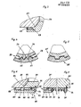
- the tool 20 shown in FIGS. 1 and 2 is used as a turning tool or as a drilling tool. It has two main components, namely a tool holder 21 and a tool head 22.
- the tool holder 21 is used to fasten the tool 10 to a machine tool, not shown.
- the design features of the tool holder and connecting elements that depend on the type and structure of the machine tool are also not shown.
- the tool head 22 carries the cutting body, which is referred to below as the cutting edge 23 and which is designed and shown here as a soldered hard metal cutting edge.
- the tool 20 is divisible.
- the tool holder 21 and the tool head 22 can be separated from one another at a separation point 24.
- the two tool parts are connected to one another by means of a coupling device 25.
- the coupling device 25 has two groups of guide and contact surfaces, namely the first contact surfaces 26 and 27 and the second contact surfaces 28 and 29 (FIG. 2), which are arranged partly on the tool holder 21 and partly on the tool head 22.
- the coupling device 25 has a tensioning device 31. Both the guide and contact surfaces 26 ... 28 as well as the clamping device 31 and its parts are arranged in the center of a common axis 32 of the tool holder 21 and the tool head 22.
- the first-mentioned guide and contact surfaces 26 and 27 are matched truncated cone surfaces, which are arranged in the region of the facing end faces of the two tool parts and are located at least approximately in the same radius of the radius.
- the frustoconical surface 26 present on the tool holder 21 is designed as an inner cone.
- the tool head 22 existing truncated cone surface 28 is designed as an outer cone.
- the two truncated cone surfaces 26 and 27 have a cone tip angle that is between 60 0 and 120 °. The size of this angular value depends, among other things, on the relationship in which the radial forces and axial forces to be transmitted occur. If the radial forces predominate, a smaller cone tip angle is more favorable.
- the truncated cone surfaces 26 and 27 are arranged on both tool parts 21 and 22 in a radius area as far as possible outside, so that the distance from the common axis 32 is as large as possible and the greatest possible torque arm is created.
- the radial dimension of the truncated cone surfaces 26 and 27 depends on the size of the forces to be transmitted and the permissible surface pressure, taking into account the inevitable elastic deformations.
- the truncated cone surfaces 26 and 27 are limited to the smallest possible area of the radius, so that given the outer dimensions of the two tool parts, the largest possible space is available for the other individual parts, in particular the parts of the clamping device 31.
- the second guide and contact surfaces 28 and 29 act as tangential coupling surfaces. These tangential coupling surfaces 28 and 29 are formed by the flat tooth flanks 33 and 34 of the teeth 35 and 36 of a regular serration (FIG. 4) on both sides.
- the teeth 35 arranged on the tool holder 21 and directed inwards with the tooth flanks 33 together form the hub profile and the teeth 36 arranged on the tool head and directed outwards with the tooth flanks 34 together form the wave profile of the serration.
- flanks of a regular multi-groove profile can also be used as tangential coupling surfaces 28 'and 29', as indicated in FIG. 5.
- the clamping device 31 has a clamping bolt 37, a collet 38 and a pulling device 39 which actuates the collet 38.
- the clamping bolt 37 is detachably connected to the tool head 22, and it is also guided exactly in the center thereof.
- the clamping bolt 37 has for this purpose (FIG. 2) a cone-shaped guide and contact surface 41 (as an outer cone) which is arranged on the circumferential surface of a collar 42 which is present at a certain axial distance from the end of the clamping bolt 37.
- a cylindrical section with a screw thread 43 adjoins the collar 42 in the direction of the end of the clamping bolt 37.
- This screw thread 43 is designed as a sawtooth thread, the thread flank of which is oriented approximately at right angles to the common axis 32 and faces away from the tool head 22.
- a final section with a cylindrical guide surface 44 adjoins this section with the screw thread 43.
- a frustoconical guide and contact surface 45 (as an inner cone), followed by a section with a nut thread 46 and a last section with a smooth cylindrical guide surface 47, which are matched to the corresponding counter surfaces on the clamping bolt 37 .
- a cylindrical collar 48 which is provided with two or more flats 49 so that the clamping bolt 37 can be tightened on the tool head 22.
- the clamping bolt 37 has two coupling surfaces 51 and 52 at a distance from the fastening points with the tool head 22.
- These coupling surfaces 51 and 52 are formed as truncated cones. They have the same inner diameter and the same outer diameter. Their cone tip angle is between 45 ° and 90 ° and is preferably 60 °.
- the surface normal of these coupling surfaces 51 and 52 has a radially outward component and an axial component directed towards the tool head 22, the surface normal of both coupling surfaces 51 and 52 being aligned parallel to one another.
- the two coupling surfaces 51 and 52 on the clamping bolt 37 have a certain axial distance from one another.
- a cylindrical transition surface 53 and 54 adjoins the smaller diameter of the coupling surfaces 51 and 52.
- the transition surface 53 extends from the coupling surface 51 into the vicinity of the fastening point with the tool head 22.
- the transition surface 54 extends from the coupling surface 52 to the rear of the coupling surface 51.
- the back of both coupling surfaces is also generally a truncated cone surface, which, however, has a conical apex angle that is considerably obtuse than the coupling surface.
- the collet 38 arranged in the tool holder 21 is divided into separate jaws 55 by several longitudinal slots. These are made by means of elastic rubber spring elements held together, which are arranged in the slots (Fig. 11 and 12) and are connected to the individual jaws, in particular cast or vulcanized thereon, or which are glued thereto. If information about individual design features, in particular about the arrangement, alignment or dimensions of one of their individual features, is given in relation to the collet chuck 38, this also applies to the individual clamping jaws with the proviso that these have the same mutual assignment as before the division of the collet body.
- the collet 38 is a hollow cylindrical structure. It is provided on its inside with two coupling surfaces 57 and 58, which are designed as frustoconical surfaces. Their surface normal has the opposite orientation as the surface normal of the coupling surfaces 51 and 52 on the clamping bolt 37.
- the coupling surfaces 57 and 58 have the same inner diameter and the same outer radius, which are slightly larger than the corresponding dimensions of the coupling surfaces 51 and 52 on the clamping bolt 37.
- These coupling surfaces 57 and 58 have the same axial distance from one another that the coupling surfaces 51 and 52 have on the clamping bolt 37. They are also arranged on the collet 38 so that they are in their clamping position (Fig. 1) for the most part in the same axial sections as the coupling surfaces 51 and 52 on the clamping bolt and rest on these.
- transition surface 59 and 60 At the outer circumference of the coupling surfaces 57 and 58 in the direction facing away from the tool head 21, there is a cylindrical transition surface 59 and 60, respectively, the axial extent of which is somewhat larger than the largest axial displacement of the collet 38 between its clamping position (FIG. 1) and its Release position (Fig. 2). From the inner radius of the coupling surfaces 57 and 58, a likewise cylindrical transition surface 61 and 62 extends in the opposite axial direction. The above The transition surface 61 extends to the end of the collet 38. The transition surface 62 extends to the cross-sectional plane at which the transition surface 59 located further out ends, so that there is a more or flat annular transition surface between them.
- the collet 38 has on its outside two cylindrical contact surfaces 63 and 64 and two frustoconical guide surfaces 65 and 66 (FIG. 1).
- the cylindrical guide surfaces 63 and 64 have the same outer radius with each other.
- One of the frustoconical guide surfaces 65 and 66 adjoins one of the cylindrical guide surfaces 63 and 64 on the side facing away from the tool head 22, where it tapers from there.
- the surface normal of the frustoconical guide surfaces 65 and 66 accordingly have a radially outward component and an axial component away from the tool head 22.
- the surface normal of both frustoconical guide surfaces 65 and 66 are aligned parallel to one another.
- the difference in radius between the two frustoconical guide surfaces is at least approximately the same size and at the same time larger than the difference in radius between the coupling surfaces 51 and 52 on the clamping bolt 37.
- a cylindrical transition surface 67 and 68 connects to the smaller diameter of the frustoconical guide surfaces 65 and 66.
- the transition surface 67 extends to the beginning of the adjacent cylindrical guide surface 64.
- the transition surface 68 extends to the end of the collet 38.
- These are arranged on a sleeve-shaped guide part 69 of the tool holder 21, which in a manner not shown is connected to the tubular main part 70 of the tool holder 21, at the front end of which is the frustoconical guide and contact surface 26.
- These inner guide surfaces are two cylindrical guide surfaces 71 and 72 and two frustoconical guide surfaces 73 and 74.
- the cylindrical guide surfaces 71 and 72 have the same inner diameter, which is at least approximately equal to twice the outer diameter of the outer cylindrical guide surfaces 63 and 64 on the collet 38.
- Their surface normals which are aligned parallel to one another, have at least approximately the opposite orientation as the surface normals of the outer frustoconical guide surfaces 65 and 66 on the collet 38.
- the inner frustoconical guide surfaces 73 and 74 on the guide part 69 have a radius difference that is greater than the radius difference of the Coupling surfaces 51 and 52 on the clamping bolt 37.
- the smaller radius of the frustoconical guide surfaces 73 and 74 is approximately the same size as the larger radius of the frustoconical outer guide surfaces 65 and 66 on the collet 38.
- a cylindrical transition surface 55 adjoins the frustoconical guide surface 74 and extends in the direction of the tool head 22 up to the cross-sectional plane at which the cylindrical guide surface 71 begins.
- the transition points between each of the inner cylindrical guide surfaces 71 and 72 and their associated frustoconical guide surface 73 and 74 are at the same axial distance as the transition points on the collet between each of the outer ones have cylindrical guide surfaces 63 and 64 and their associated frustoconical guide surfaces 65 and 66, respectively.
- the collet 38 moves axially, its clamping jaws 55 are always moved parallel to themselves, either along the cylindrical guide surfaces or along the frustoconical guide surfaces.
- the collet 38 has in its interior an annular contact surface 76 which faces the tool head 22.
- the contact surface 76 is aligned at right angles to the common axis 32. This contact surface forms part of the pulling device 39.
- a pull rod 77 which is connected or can be connected to a power drive (not shown).
- the pull rod 77 is arranged centrally to the common axis 32. It extends into the interior of the collet 38.
- the pull rod 77 is provided at its end projecting into the interior of the collet 38 with a pull head 78 which has a flat, annular contact surface 79 facing away from the tool head 22. This contact surface 79 on the pulling head 78 and the contact surface 76 facing it on the collet 38 are at least partially in the same radius range in every position of the collet 38.
- the pull rod 77 By actuating the pulling device 39, the pull rod 77 is moved away from the tool head 22 in the axial direction. It takes the collet 38 from its release or release position (FIG. 2) into the clamping position (FIG. 1).
- the jaws 55 initially move axially and at the same time radially inward, as long as the frustoconical guide surfaces 65 and 66 and 73 and 74 slide along each other.
- the frustoconical coupling surfaces 57 and 58 of the collet 38 move along a cone surface line towards the common axis 32 until they are in the same radius as the coupling surfaces 51 and 52 on the clamping bolt 37.
- the clamping jaws 55 with their coupling surfaces 57 and 58 on the coupling surfaces 51 and 52 of the clamping bolt 37 perform a small relative movement in the direction of their common surface lines, as a result of which the radial play between the outer cylindrical guide surfaces 63 and 64 the jaws 55 and inner cylindrical guide surfaces 71 and 72 of the guide part 69 is eliminated and the clamping jaws 55 exert a radial clamping force component which is accompanied both by an axial clamping force component and both inwards in the direction of the clamping bolt 37 and outwards in the direction of the guide part 69.
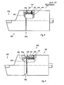
- FIGS. 6 to 9 are modified with regard to the arrangement and / or configuration of the tangential coupling surfaces.
- a frustoconical guide and contact surface 83 and 84 designed as an inner cone and an outer cone, are present on the tool holder 81 and on the tool head 82, which serve for the axial and radial coupling of the two tool parts .
- Both the tool holder 81 and the tool head 82 are provided with tangential coupling surfaces 85 and 86, which are designed as a wave profile on both tool parts.
- the tangential coupling surfaces 85 and 86 are preferably serrated again. Both wave profiles are identical to one another with regard to the profile features of the serration.
- a locking device 89 for the coupling sleeve 87 is provided.
- a snap ring 93 with a circular cross-sectional area is inserted therein. Since the circumferential groove 92 lies on the coupling sleeve 87 in the radius of its hub profile with the coupling surfaces 88, the snap ring 93 inserted into the circumferential groove is also in the radius of the shaft profile with the coupling surfaces 85 on the tool holder 81.
- the axial stop for the coupling sleeve 87 is formed by a locking ring 94, which is inserted into a circumferential groove 95 matched to it on the outside of the tool holder 81.
- the embodiment of the tool shown in FIG. 7 is modified compared to the embodiment shown in FIG. 6 with respect to part of the locking device for the coupling sleeve 87.
- the coupling sleeve 87 is provided, as previously, with a circumferential groove 92 into which the snap ring 93 is inserted, which in turn bears against the shaft profile 85.
- the circumferential groove 95 'for the locking ring 94 and this itself are arranged at a certain axial distance from the end of the coupling sleeve 87.
- a helical compression spring 96 is inserted, which is guided on the outside of the tool holder 81 'and which is with their Supports ends via a disk-shaped spring plate 97 or 98 on the face of the coupling sleeve 87 or the locking ring 94 facing it.
- This design of the locking device gives the coupling sleeve 87 a firm stop in the direction of the tool head, whereas it is supported elastically in the opposite direction.
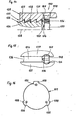
- the tool holder 101 and the tool head 102 rest axially and radially on two frustoconical guide and contact surfaces 103 and 104, respectively.
- a serrated hub profile with tangential coupling surfaces 105 and 106 is provided on the inside of both the tool holder 101 and the tool head 102.
- These hub profiles which are identical to one another with regard to the profile design and the radius of the cutter, are coupled to one another by a coupling sleeve 107 which is provided with a corrugated profile with tangential coupling surfaces 108.
- the locking device which is also desirable in this embodiment of the tangential coupling, could be designed similarly to the locking device shown in FIG. 6, wherein an inner shoulder of the tool holder 101 could be used as an axial stop in the inner coupling sleeve 107.
- the modified embodiment of the locking device 111 shown in FIGS. 8 and 9 has a locking pin 112. These include a cylindrical through hole 113 in an outer wall part of the tool holder 101 and a likewise cylindrical through hole 114 in the coupling sleeve 107. The two through holes 113 and 114 are aligned radially and are aligned with one another.
- the through-hole 103 is expediently matched to the outer diameter of the locking pin 112 in such a way that there is a floating fit.
- the through hole 114 in the coupling sleeve 107 is made somewhat larger, so that at least a sliding fit or better still a clearance fit is created.
- the locking pin 112 fixes the coupling sleeve 107 to a certain extent in the axial direction, but does not prevent it from adjusting with its shaft profile in the radial and tangential direction to the hub profile on the tool holder 101 and on the tool head 102.
- the locking pin 112 can be pushed into the interior of the tool holder 101 from the outside, so that the coupling sleeve 107 can then be pulled out of the tool holder 101. For this reason, it is useful to choose a locking pin for the locking pin 111. Grooved pins can also be used, however, if the coupling sleeve 107 has to be removed from the tool holder 101 only rarely.
- the tool holder 121 and the tool head 122 are coupled to one another at the end facing each other in one of the previously described ways by means of frustoconical guide and contact surfaces and by means of tangential coupling surfaces.
- the clamping device 123 has a clamping bolt 124 and a collet 125.
- the clamping bolt 124 is connected to the tool head 122 in the manner described.
- the clamping bolt For the coupling with the collet 125 124, the clamping bolt a cylindrical Bt 'lzengewinde 126 (FIG. 14).
- the tool head 122 facing thread flank forms the coupling surface 127 of the clamping bolt 124. It has an angle of inclination with respect to the common axis 128 which is between 22.5 ° and 45 °, preferably at least approximately 30 °.
- the other thread flank has a larger angle of inclination, for example of approximately 3 °, as is common with sawtooth threads.
- the coupling surface 129 on the collet 125 is formed by the flank of a cylindrical nut thread 130 facing away from the tool head 122, which is matched to the bolt thread 126 of the clamping bolt 124.
- the outer guide surface 131 of the collet 125 is a smooth circular cylinder surface. Accordingly, the inner guide surface 132 on the tool holder 122 is also a smooth circular cylinder surface.
- the collet 125 is coupled to a rotating device which transmits its rotary movement to the collet 125, for example by means of the pull rod 133 and its pulling head 134.
- driving pins 135 are arranged on the traction head 134, which engage in the slots 136 between two adjacent clamping jaws 137 of the collet 125.
- FIGS. 12 and 13 An embodiment which is partially modified and partially matches the tool 120 'relative to the tool 120 can be seen from FIGS. 12 and 13, FIG. 10 being able to serve largely as an associated longitudinal section.
- the at least partially matching and partially modified parts are identified by the same reference numbers, which are provided with an apostrophe to distinguish them.
- Longitudinal grooves 141 are provided on the clamping bolt 124 'and are aligned parallel to the common axis 128. They extend from the free end of the clamping bolt 124 'towards the work tool head 122 out beyond the last thread of the bolt thread 126 '.
- the groove base 142 of these longitudinal grooves 141 has a radial distance from the common axis 128 which is smaller than half the core diameter of the bolt thread 126 '.
- the longitudinal grooves 41 are evenly distributed on the circumference. Their circumferential extent is at least approximately equal to the total circumferential length divided by twice the number of longitudinal grooves.
- Longitudinal grooves 143 are also provided on the inside of the collet 125 '. These are also aligned with the common axis 128. They extend from the free end of the collet 125 away from the tool head 122 to beyond the last thread turn of the bolt thread 126 'on the clamping bolt 124'. Its groove base 144 is at a radial distance from the common axis 128, which is larger than the outer radius of the bolt thread 126 'on the clamping bolt 124'. They are distributed evenly over the circumference in the same way as the longitudinal grooves 142 on the clamping bolt 124 '.
- the separating slots 136' lie in the same circumferential area as their longitudinal grooves 143, preferably in the middle thereof.
- the spring element 147 for the jaws 137 ' Rubber-elastic mass arranged in the slots 136 ' should not protrude inwards into the longitudinal grooves 143.
- a guide device 150 shown in FIGS. 14 to 16 can be used.
- the guide device 150 also has a stop 154 in the axial alignment of each longitudinal groove 143 of the collet 125 '.
- Each of the stops 154 is formed by a threaded pin 156 which is screwed into a threaded bore of a stop disc 157.
- the stop disc 157 has an outer dimension, which is smaller than twice the inside diameter of the nut thread 130 '. It has a number of longitudinal grooves 143 on the collet 125 'corresponding number of radial projections 158, on each of which there is one of the threaded bores for one of the threaded pins 156.
- the projections 158 have a radial extension that is slightly larger than the radius of the inner surface 159, which adjoins the nut thread 130 ′. In the immediate vicinity of the inner end of the nut thread 130 'there are recesses 160 in the area of the slots 136'.
- the axial and tangential dimensions of the recesses 160 and the projections 158 are coordinated with one another in such a way that the projections 158 fit into the recesses 160 and can rest on their walls in the axial direction.
- the radial coverage of the projections 158 and the recesses 160 is chosen to be at most as large as the clamping jaws 137 'allow the clamping jaws 137' to spread apart due to the elasticity of the rubber-elastic mass located between them. If this is not sufficient in individual cases, instead of the projections 158 formed integrally with it, self-holding pins such as spring pins or grooved pins or also grub screws can be inserted into corresponding radial bores of the stop disk instead of the projections 158 formed integrally therewith. With these is a bigger one. possible degree of coverage.
- the guide device 150 interacts with the tensioning device 123 'in such a way that after the front thread flank 155 or the inwardly adjacent end face of the tensioning bolt 124' strikes, the collet 125 'is pushed back somewhat against the force of the spring 155.
- Her coupling surfaces 129 'always remain in the tangential line of alignment of the coupling surfaces 127' of the clamping bolt 124 '.
- the clamping pliers 125 'together with the clamping bolt 124' are pulled completely from the pull rod 133 into the clamping position.
- the relatively weak spring 151 yields sufficiently far.
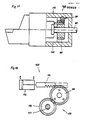
- 17 and 18 show two different rotating devices for rotating the collet.
- the rotating device 165 has a gear 166 which is simply rotatably mounted on the pull rod 167 of the clamping device in question.
- the gear 166 is coupled to the collet 168 in the tangential direction by means of a plurality of coupling pins 169, which are seated on the gear 166 in axially aligned cylindrical through holes and extend axially into the slots between two jaws of the collet 168.
- a toothed rack 171 is guided on the tool holder 172 so as to be longitudinally displaceable parallel to a tangential plane of the toothing of the gear wheel 166.
- the rack 171 is coupled inside or outside of the tool holder 172 to a linear adjustment drive 173, which is designed, for example, as a pneumatic or hydraulic piston drive. Instead, a threaded spindle drive with a rotary motor can also be used.
- the track wheel 166 and the parts connected to it in a rotationally fixed manner can either be rotated freely or can be brought into a specific thrust position by means of another rotating device.
- the toothed rack 171 moves a certain distance, engaging in the toothing of the toothed wheel 166 and rotating it by a corresponding angle of rotation. If, on the other hand, the toothed rack 171 is designed and arranged in such a way that it meshes constantly with the toothed wheel 166, then it can no longer be freely rotated and can only carry out the rotary movements triggered by the toothed rack 171.
- FIG. 18 shows a second rotating device 175.
- This has a gearwheel 176 which constantly meshes with the gearwheel 166 which is coupled in a rotationally fixed manner to the associated collet 168.
- the gearwheel 176 is connected via a shaft 177 to a rotary drive (not shown), with this actuation via the gearwheel 176 and the gearwheel 166 the collet can either be rotated by a specific angle of rotation or by several revolutions, as is required in a clamping device, in which the clamping bolt and the collet are coupled together by means of a thread.
Landscapes
- Engineering & Computer Science (AREA)
- Mechanical Engineering (AREA)
- Gripping On Spindles (AREA)
Applications Claiming Priority (2)
| Application Number | Priority Date | Filing Date | Title |
|---|---|---|---|
| DE3326567 | 1983-07-23 | ||
| DE3326567 | 1983-07-23 |
Publications (1)
| Publication Number | Publication Date |
|---|---|
| EP0132825A1 true EP0132825A1 (fr) | 1985-02-13 |
Family
ID=6204720
Family Applications (1)
| Application Number | Title | Priority Date | Filing Date |
|---|---|---|---|
| EP84108698A Withdrawn EP0132825A1 (fr) | 1983-07-23 | 1984-07-23 | Outil divisible pour l'usinage |
Country Status (3)
| Country | Link |
|---|---|
| US (1) | US4580472A (fr) |
| EP (1) | EP0132825A1 (fr) |
| DE (1) | DE3427125C2 (fr) |
Cited By (1)
| Publication number | Priority date | Publication date | Assignee | Title |
|---|---|---|---|---|
| GB2175227A (en) * | 1985-05-08 | 1986-11-26 | Forkardt Paul Gmbh | Device for clamping tools to a tool holder of a machine-tool |
Families Citing this family (11)
| Publication number | Priority date | Publication date | Assignee | Title |
|---|---|---|---|---|
| DE3363749D1 (en) * | 1982-07-30 | 1986-07-03 | Gerhard Rall | Cutting tool |
| SE455059B (sv) * | 1984-05-25 | 1988-06-20 | Sandvik Ab | Verktygskoppling mellan ett skerverktyg och en maskinspindel |
| US5542792A (en) * | 1993-12-21 | 1996-08-06 | Waukesha Cutting Tools, Inc. | Cutting device with removable nosepiece |
| RU2133175C1 (ru) * | 1998-03-13 | 1999-07-20 | Государственное производственное объединение "Ульяновский машиностроительный завод" | Резцовый блок |
| SE516524C2 (sv) * | 2000-05-18 | 2002-01-22 | Sandvik Ab | Verktygskoppling |
| SE516501C2 (sv) * | 2000-05-18 | 2002-01-22 | Sandvik Ab | Verktygskoppling |
| SE527703C2 (sv) * | 2004-08-19 | 2006-05-16 | Sandvik Intellectual Property | Roterbart verktyg samt skärhuvud med axiella serraterade ingreppsorgan |
| US20070071545A1 (en) * | 2005-08-26 | 2007-03-29 | Honeywell International, Inc. | Lubricated Hirth serration coupling |
| US8328476B2 (en) * | 2008-03-18 | 2012-12-11 | Irwin Industrial Tool Company | Quick change arbor, hole cutter, and method |
| US8360696B2 (en) * | 2008-03-18 | 2013-01-29 | Irwin Industrial Tool Company | Quick change arbor, hole cutter, and method |
| TWM576950U (zh) | 2017-07-25 | 2019-04-21 | 美商米沃奇電子工具公司 | 成角適配器 |
Citations (6)
| Publication number | Priority date | Publication date | Assignee | Title |
|---|---|---|---|---|
| US3520228A (en) * | 1967-04-10 | 1970-07-14 | Giddings & Lewis | Spindle orienting and drawbolt malfunction sensing machine tool control system |
| DE1652715B2 (de) * | 1967-07-13 | 1971-08-05 | Automatische werkzeugmaschine mit numerisch gesteuertem werkzeugwechsel | |
| DE1652673A1 (de) * | 1967-02-04 | 1971-11-18 | Glacier Metal Co Ltd | Vorrichtung zum Auswechseln von Werkzeugen |
| DE1777019B2 (de) * | 1967-08-25 | 1979-11-29 | Kearney & Trecker Corp., Milwaukee, Wis. (V.St.A.) | Werkzeugmaschine mit einer Werkzeugwechseleinrichtung |
| US4196506A (en) * | 1976-09-07 | 1980-04-08 | Giddings & Lewis, Inc. | Tool changer machining center |
| DE2150558B2 (de) * | 1970-10-14 | 1981-04-16 | Société Genevoise d'instruments de Physique, Geneve | Bohrkopf |
Family Cites Families (9)
| Publication number | Priority date | Publication date | Assignee | Title |
|---|---|---|---|---|
| DE664965C (de) * | 1938-09-10 | Erich Maeder | Stahlhalter mit Spannkeil fuer den Schneidstahl | |
| DE2450323C3 (de) * | 1974-10-23 | 1978-12-21 | Friedrich Deckel Ag, 8000 Muenchen | Werkzeugspannvorrichtung |
| US3975984A (en) * | 1975-09-19 | 1976-08-24 | Caterpillar Tractor Co. | Self aligning collect for machine tools |
| JPS6216261Y2 (fr) * | 1978-07-21 | 1987-04-24 | ||
| SE433574B (sv) * | 1978-09-26 | 1984-06-04 | Sandvik Ab | Skerverktyg och verktygselement for detta |
| DE3007440A1 (de) * | 1980-02-28 | 1981-09-17 | Fried. Krupp Gmbh, 4300 Essen | Werkzeugeinrichtung mit wechselbarem werkzeugtraeger |
| SU884879A1 (ru) * | 1980-03-24 | 1981-11-30 | Киевский Ордена Ленина Политехнический Институт Им.50-Летия Великой Октябрьской Социалистической Революции | Цанговый патрон |
| DE3243948A1 (de) * | 1982-11-27 | 1984-07-05 | Gerhard 7142 Marbach Rall | Teilbares werkzeug fuer die spanabhebende bearbeitung |
| US4499800A (en) * | 1983-04-04 | 1985-02-19 | General Electric Company | Tool holder clamping means |
-
1984
- 1984-07-23 DE DE3427125A patent/DE3427125C2/de not_active Expired - Fee Related
- 1984-07-23 US US06/633,254 patent/US4580472A/en not_active Expired - Fee Related
- 1984-07-23 EP EP84108698A patent/EP0132825A1/fr not_active Withdrawn
Patent Citations (6)
| Publication number | Priority date | Publication date | Assignee | Title |
|---|---|---|---|---|
| DE1652673A1 (de) * | 1967-02-04 | 1971-11-18 | Glacier Metal Co Ltd | Vorrichtung zum Auswechseln von Werkzeugen |
| US3520228A (en) * | 1967-04-10 | 1970-07-14 | Giddings & Lewis | Spindle orienting and drawbolt malfunction sensing machine tool control system |
| DE1652715B2 (de) * | 1967-07-13 | 1971-08-05 | Automatische werkzeugmaschine mit numerisch gesteuertem werkzeugwechsel | |
| DE1777019B2 (de) * | 1967-08-25 | 1979-11-29 | Kearney & Trecker Corp., Milwaukee, Wis. (V.St.A.) | Werkzeugmaschine mit einer Werkzeugwechseleinrichtung |
| DE2150558B2 (de) * | 1970-10-14 | 1981-04-16 | Société Genevoise d'instruments de Physique, Geneve | Bohrkopf |
| US4196506A (en) * | 1976-09-07 | 1980-04-08 | Giddings & Lewis, Inc. | Tool changer machining center |
Cited By (1)
| Publication number | Priority date | Publication date | Assignee | Title |
|---|---|---|---|---|
| GB2175227A (en) * | 1985-05-08 | 1986-11-26 | Forkardt Paul Gmbh | Device for clamping tools to a tool holder of a machine-tool |
Also Published As
| Publication number | Publication date |
|---|---|
| DE3427125A1 (de) | 1985-01-31 |
| DE3427125C2 (de) | 1997-01-30 |
| US4580472A (en) | 1986-04-08 |
Similar Documents
| Publication | Publication Date | Title |
|---|---|---|
| EP1184113B1 (fr) | Dispositif de serrage pour un arbre creux | |
| DE3324312C2 (de) | Werkzeugmaschine mit Werkzeugwechselvorrichtung | |
| EP2826579B1 (fr) | Réceptacle de scie cloche et assemblage d'outil | |
| EP0158182A2 (fr) | Tête à fraiser et percer pour une machine-outil | |
| EP3760352A1 (fr) | Mandrin á compensation pour le serrage de pièces dans centres d'usinage | |
| WO1998041350A1 (fr) | Machine-outil | |
| WO2011015259A1 (fr) | Support d'outil avec porte-outils interchangeables et porte-outil | |
| DE3406498C1 (de) | Werkzeugmaschinenspindel und hierzu passender Werkzeughalter | |
| EP0132825A1 (fr) | Outil divisible pour l'usinage | |
| DE3610671C2 (fr) | ||
| DE69308053T2 (de) | Vorrichtung für die Hauptspindel einer Werkzeugmaschine | |
| DE3617695C2 (fr) | ||
| EP0123220A2 (fr) | Broche de machine-outil et porte-outil correspondant | |
| EP0169543B1 (fr) | Outil divisible pour l'usinage | |
| DE1602825C3 (de) | Vorrichtung zur lösbaren Befestigung eines Spannfutters | |
| DE4110720C2 (fr) | ||
| EP0244667A2 (fr) | Dispositif de fixation interchangeable d'un mandrin à la broche d'une machine-outil | |
| DE3233868A1 (de) | Einspanneinrichtung fuer hohle werkstuecke | |
| DE3334001C2 (fr) | ||
| DE3427124A1 (de) | Teilbares werkzeug fuer die spanabhebende bearbeitung | |
| DE4025745C2 (fr) | ||
| DE10329423B4 (de) | Spannvorrichtung für Werkzeugmaschinen und entsprechende Werkzeugmaschine | |
| EP0333923A2 (fr) | Mandrin à changement rapide, spécialement pour l'usinage de filetages intérieurs et extérieurs | |
| DE3326665C2 (de) | Teilbares Werkzeug für die spanabhebende Bearbeitung | |
| EP3670046A1 (fr) | Dispositif d'entraînement |
Legal Events
| Date | Code | Title | Description |
|---|---|---|---|
| PUAI | Public reference made under article 153(3) epc to a published international application that has entered the european phase |
Free format text: ORIGINAL CODE: 0009012 |
|
| AK | Designated contracting states |
Designated state(s): AT BE CH FR GB IT LI NL SE |
|
| 17P | Request for examination filed |
Effective date: 19850813 |
|
| 17Q | First examination report despatched |
Effective date: 19861117 |
|
| D17Q | First examination report despatched (deleted) | ||
| STAA | Information on the status of an ep patent application or granted ep patent |
Free format text: STATUS: THE APPLICATION IS DEEMED TO BE WITHDRAWN |
|
| 18D | Application deemed to be withdrawn |
Effective date: 19890304 |